Author | BanJiang
Smart Chassis Technology (17)| Introduction to One-box Electro-mechanical Brake System
According to the different brake actuators, the wire-controlled brake system can be divided into Electro-Hydraulic Brake (EHB) and Electro-Mechanical Brake (EMB). Among them, EHB is based on traditional hydraulic brake system, and electronic devices replace some mechanical parts’ functions. It uses brake fluid as the power transmission medium and is equipped with a hydraulic backup brake system, which is currently the mainstream technology. Furthermore, according to the degree of integration, EHB can be divided into Two-box and One-box.
The previous article introduced the working principle of the One-box electro-mechanical brake system, and this article will discuss how One-box satisfies the requirements of brake systems for assisted driving and autonomous driving.
Requirements of the Assisted Driving System for One-box
For assisted driving cars, when the system fails, it is required that the system report the fault to the driver correctly and promptly. The driver is responsible for running the vehicle to the safe state, and the continuous braking capability of the brake system is essential to help the driver complete this task. EU ECE R13 and national standard GB 21670 make mandatory requirements for the emergency braking capability of the brake system:
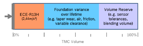
When the basic braking function fails, the average deceleration of emergency braking should not be less than 2.44 m/s² when the driver pedal inputs 500 Nm.
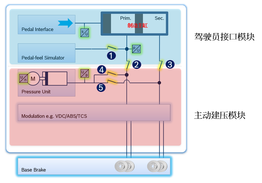
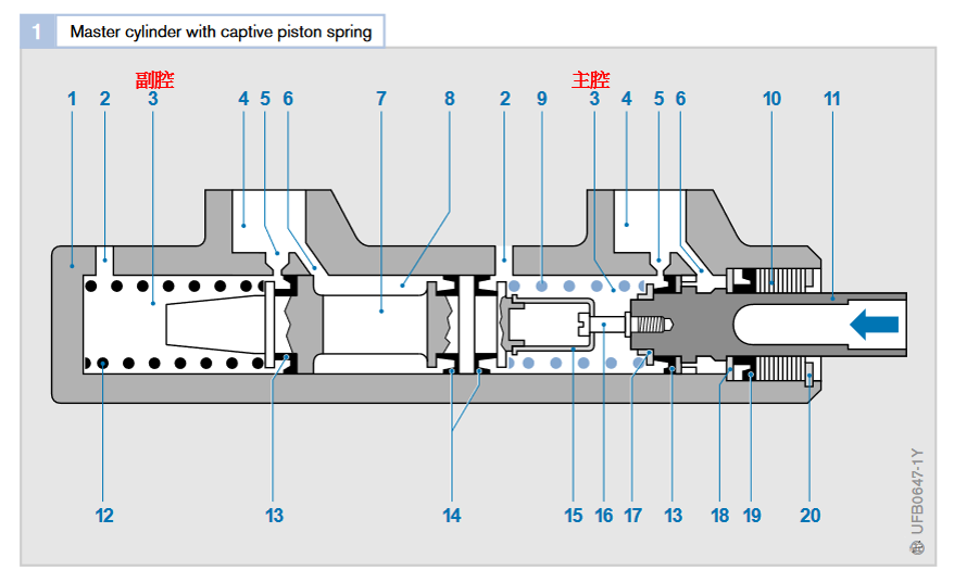
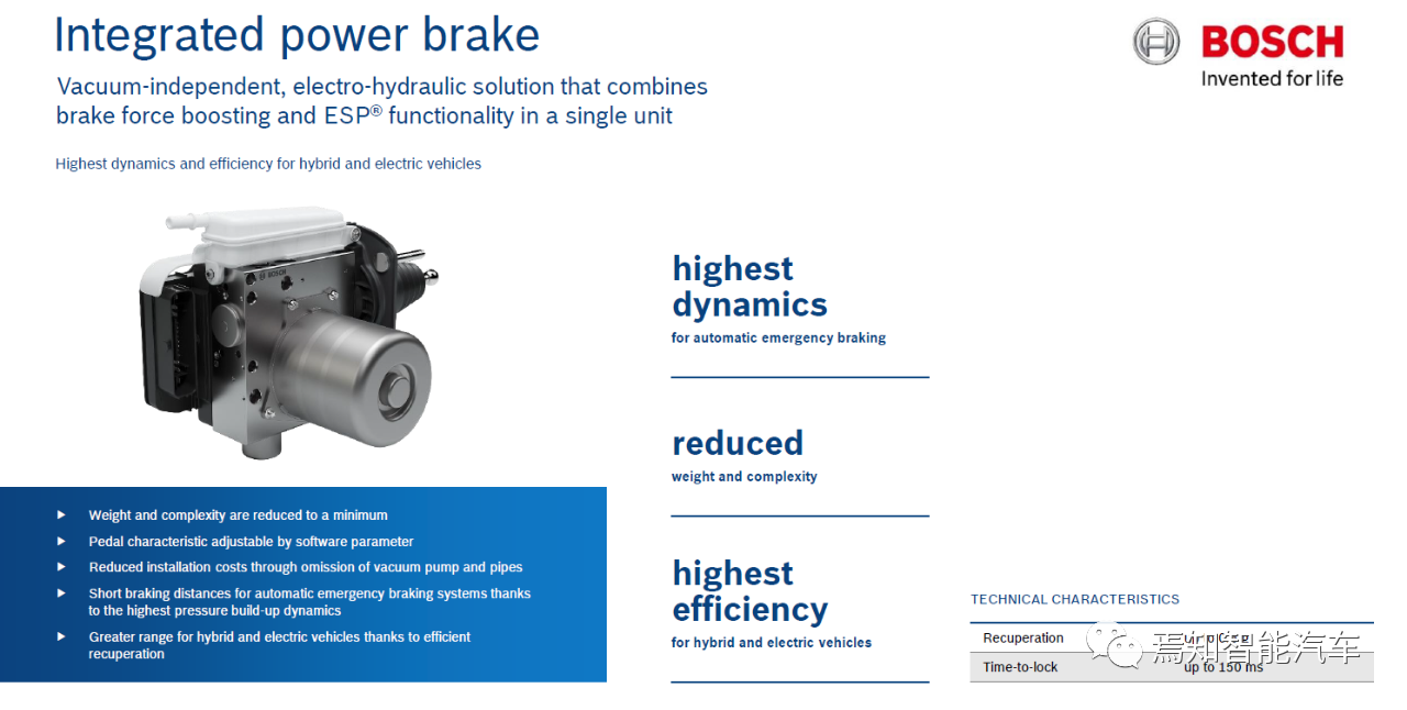
To meet this requirement, One-box designed a mechanical backup (Hydraulic Backup) to ensure that the driver can still produce deceleration by stepping on the brake pedal after the basic power-assisted system fails. Taking the IPB product of Bosch One-box as an example, when the active pressure-building module cannot work correctly (such as power failure, power-assisted motor failure, etc.), the system enters the mechanical backup mode. At this time, valves 1, 4, and 5 are closed, and 2 and 3 are opened. The driver can push the piston in the brake master cylinder by stepping on the pedal to push the brake fluid into four wheel cylinders, thus generating vehicle deceleration, as shown in the figure below.
The brake master cylinder is a dual-circuit design, and the brake pipes of the primary pressure chamber and secondary pressure chamber are respectively connected to the brake cylinders of two wheels, and which two wheels are connected depends on the ‘X’ layout or ‘II’ layout, with passenger cars usually being ‘X’ layout. In order to consider the extreme case of brake pipe leakage in the primary or secondary chamber under the mechanical backup mode, Bosch IPB has higher requirements for the brake design under the mechanical backup, ensuring that the non-leaking brake circuit can still provide a deceleration not less than 2.44m/s² when the driver pedal inputs 500Nm. Under this design, when no pipe leakage occurs, IPB degrades to the mechanical backup mode, and the 500Nm pedal input can generate a deceleration of 4.88m/s².
It is worth mentioning that because the One-box belongs to the brake pedal decoupling structure, the design of the brake master cylinder of One-box usually reduces the diameter of the cylinder. Under normal assist functions, the same good pressure building effect can be maintained without affecting the driver’s pedal feeling. However, the design of the cylinder diameter reduction needs to consider the impact under mechanical backup. For current car designs, the pedal ratio and maximum depth of the brake pedal cannot be changed, and in the case of the unchanged length of the brake master cylinder, the reduction of the cylinder diameter means that the brake fluid that One-box can flow into the wheel cylinders will be reduced to the same brake pedal depth as eBooster or vacuum booster.. Therefore, to ensure that the mechanical backup can meet regulatory requirements, the structural design of the brake master cylinder needs to be considered.
Requirements of One-box Braking System for Autonomous Driving System
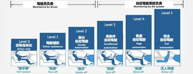
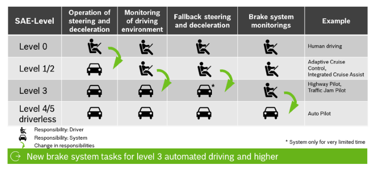
According to SAE J3016, for Level 3 or higher autonomous driving systems, the system must be able to provide braking or steering capabilities in the event of a single failure to ensure that the vehicle can enter a safe state and avoid causing personal injuries. As the responsibility for achieving this safety goal shifts from the driver to the autonomous driving system, it means that the mechanical backup, which relies on the braking pedal input in the One-box braking system, cannot meet this safety goal.
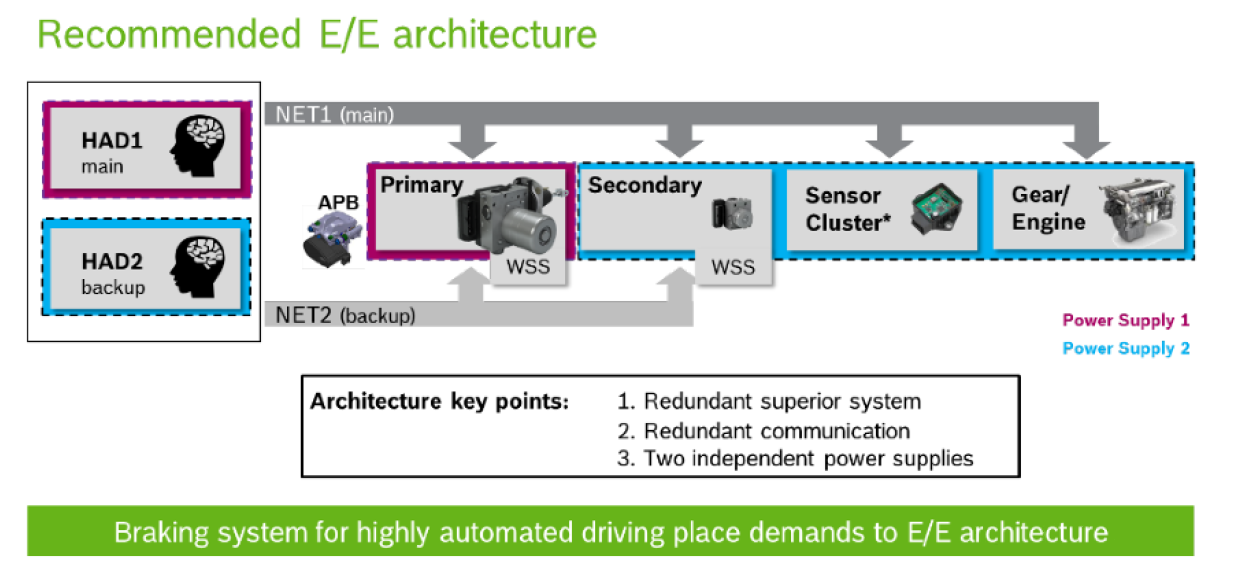
It is currently a widely accepted industry standard that vehicles supporting Highly Automated Driving (HAD) must have the following redundant designs to ensure that the vehicle can enter a reasonable safe state in the event of a single failure. Regardless of whether the safe state is defined as “stopping in the current lane” or “stopping in the emergency lane”, the redundancy of the braking system is indispensable.
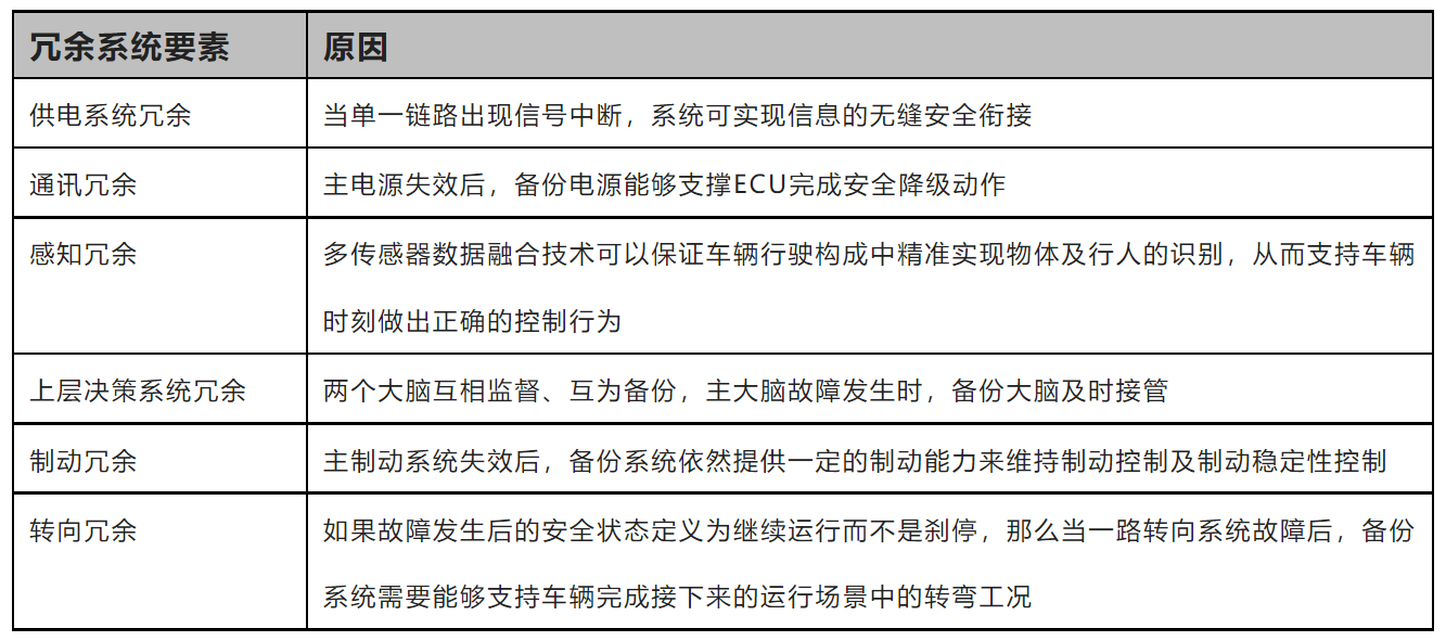
After the main brake system fails, the backup system still provides some braking capacity to maintain brake control and stability control.
Steering redundancy
If the safe state after a failure is defined to be continued running instead of stopping, then when one of the steering systems fails, the backup system needs to be able to support the vehicle to complete the turning process in the following driving scenario.
To achieve brake redundancy, One-box needs to be equipped with an independent brake unit RBU (Redundant Brake Unit). The brake circuit connection between One-box and RBU is shown in the following figure. In addition to being connected to One-box, the brake lines of the two outlet ports of the brake master cylinder are also connected to the input end of RBU. The two output lines of RBU are respectively connected to the wheel cylinder circuit in IPB.
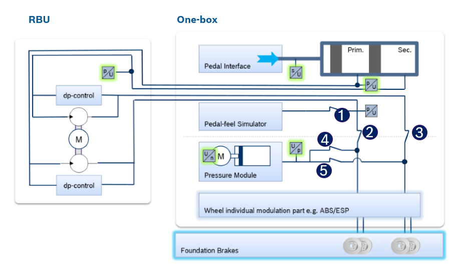
Under normal circumstances, One-box responds to braking requests from the upper-level brake system, and valves 1, 2 and 3 are closed. The electric motor in the active pressure building module pushes the push rod to inject brake fluid into the wheel cylinder through the open valves 4 and 5 to complete the pressure building process. When the One-box system fails, the system enters the brake backup mode, where valves 2 and 3 are open, and valves 1, 4, and 5 are closed. The electric motor in RBU works to inject the hydraulic fluid in the brake master cylinder into the wheel cylinder through valves 2 and 3 for pressure building.### High-Speed Autonomous Driving
In addition to requiring the basic braking function redundancy of the braking system, high-speed autonomous driving also requires redundancy of longitudinal stability, which requires RBUs to have the ability to control longitudinal stability. Currently, the RBU solutions on the market are mostly “downgraded” from the chassis electronic stability system (ESC, Electric Stability Controller), which can achieve longitudinal stability control. The difference is that the RBU can only adjust the pressure of two wheel ends arranged in an ‘X’ or ‘II’ shape at the same time, and cannot adjust the pressure of all four wheel ends at the same time. Therefore, the control performance is limited compared to ESC. However, since the autonomous driving system will quickly enter a safe state after the One-box fails, the operating time of the vehicle is greatly restricted. From the perspective of safety probability, this “downgraded” design is acceptable, and it also optimizes the cost of the “One-box + RBU” brake combination.
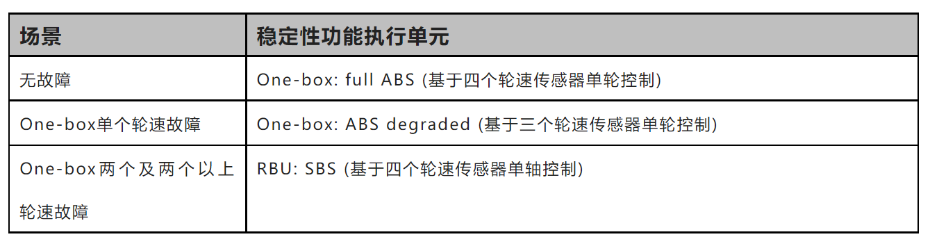
The control and takeover strategy of the “One-box + RBU” brake combination can be summarized as follows (the control strategy is not unique, and the strategy may be adjusted according to different E/E architectures):

In order to achieve the requirement of longitudinal stability redundancy in the autonomous driving scenario, redundant wheel speed sensors need to be installed, providing necessary wheel speed signals for both the stability function of the One-box and the stability function of the RBU. Currently, Bosch’s “Three-Level ABS” brake redundancy system based on redundant wheel speed sensors is the mainstream solution in the market.
This article is a translation by ChatGPT of a Chinese report from 42HOW. If you have any questions about it, please email bd@42how.com.