Author | Pancar
Intelligent Chassis Technology (16) | Application of Two-Box Solution ‘ESC + eBooster’ in Autonomous Driving
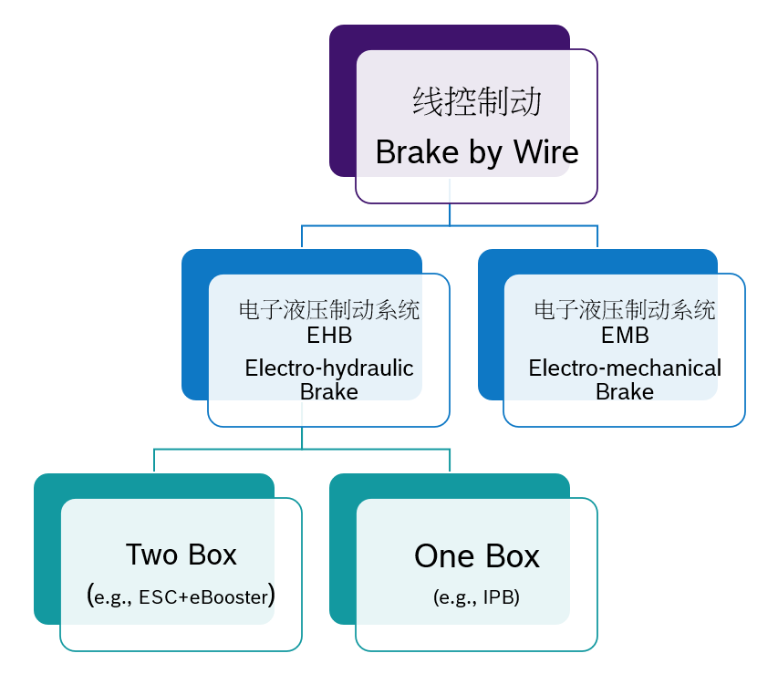
Based on different braking actuation mechanisms, the wire-controlled braking system can be divided into Electro-Hydraulic Brake (EHB) and Electro-Mechanical Brake (EMB). Among them, EHB is based on traditional hydraulic braking system, using electronic devices to replace some mechanical components, and using brake fluid as power transmission medium, while having hydraulic backup braking system, which is the current mainstream technology solution. Furthermore, according to the degree of integration, EHB can be divided into two technical solutions: Two-box and One-box.
In the previous articles, the mainstream Two-box solution “eBooster + ESC” was comprehensively introduced. From this article, the following series of articles will explain the One-box solution.
Introduction to the Working Principle of One-box Wire-controlled Braking
As mentioned in previous articles, the EHB system is divided into One-box solution and Two-box solution according to whether it is integrated with stability control function ABS/VDC.
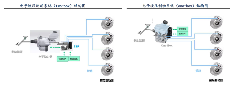
The current mainstream Two-box solution is a combination of “eBooster + ESC”. eBooster and ESC respectively realize basic braking function and stability function. ESC and eBooster share a set of hydraulic system in the vehicle. Compared with traditional vacuum booster, they can coordinate with each other to support the braking requests of drivers or intelligent driving system accurately and efficiently.
 However, the mechanical structure of eBooster means that its power-assist system is not completely decoupled from the pedal. Specifically, when the intelligent driving system requests brake control, without driver intervention, the brake pedal will dynamically rise and fall according to the deceleration rate. Therefore, eBooster needs to consider additional safety design to ensure that the pedal does not cause injury to the driver’s foot. This mechanical behavior is not popular among OEMs in the US and Chinese markets. On the other hand, the current automatic driving system has not yet become popular, and L2 and lower-level intelligent driving systems do not require redundancy in the brake system. The demand for line-control brake systems is mainly for high dynamic response characteristics and brake energy recovery. In this case, the Two-box solution does not have cost or size advantages.
Against this background, the One-box solution, which integrates basic braking functionality and stability functionality into one and achieves complete decoupling from the pedal, is becoming more popular with OEMs.
In the One-box solution, the driver’s pedal force does not act on the master cylinder, and the pedal feel is simulated by a simulator. The braking force is realized by a servo motor, so the freedom to adjust the pedal feel is greater. Moreover, in the process controlled by the intelligent driving system, One-box provides braking force without causing the brake pedal to move, achieving true decoupling.
The working principle of One-box line-control brake systems from different manufacturers at home and abroad is similar, and we will use the mainstream product, Bosch IPB (Integrated Power Brake) as an example to explain.
The main braking function of the IPB system is implemented in two parts:
- Driver interface module: Pedal – Master cylinder – Pedal simulator
- Active pressure building module: Servo motor – Hydraulic pipeline – Solenoid valveThese two parts are connected and disconnected by two solenoid valves (valves 2 and 3 shown in the figure below), which is the key to achieving the decoupling of the IPB pedal.
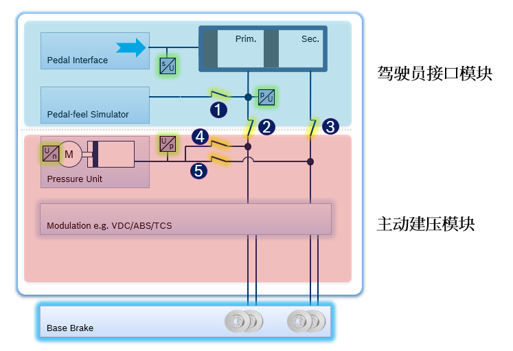
When the IPB is operating normally, when the driver steps on the brake pedal, valves 2 and 3 close, cutting off the hydraulic circuit between the driver interface module and the active release module. At the same time, valve 1 of the driver interface module opens, and the brake fluid enters the master cylinder and the pedal simulator to establish pressure after the driver steps on the pedal. The main purpose of this pressure is to provide feedback to the driver about the pedal. At this time, the pedal force-pedal travel curve is determined by the characteristics of the master cylinder and the pedal simulator. Different manufacturers can customize the characteristics of the pedal simulator according to their own preferences.

In the active pressure building module, valves 4 and 5 open. The IPB ECU recognizes the pedal displacement signal and the servo motor builds pressure based on the calibrated pedal displacement-system pressure curve. The push rod pushes the pressure in the chamber to the wheel cylinder, generating deceleration of the vehicle.
If the stability system intervention is required during the driver’s braking process, ABS/TCS/VDC adjusts the dynamic distribution of pressure or driving force on each wheel cylinder to achieve the stability of the vehicle.
When the IPB power assist function fails, the IPB enters the backup mode. At this time, valves 2 and 3 open, and valves 1, 4 and 5 close. The pressure established by the driver stepping on the pedal enters the wheel cylinder directly and generates deceleration of the vehicle. According to the ECE R13-H regulation, when the driver inputs a pedal force of 500 Nm, the mechanical brake of the IPB should generate a braking deceleration of not less than 2.44 m/s².
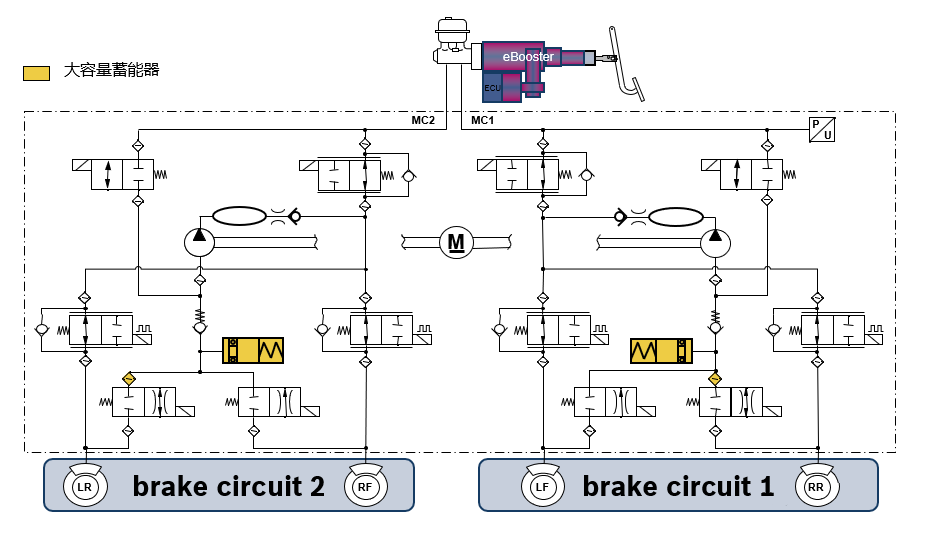
Regarding the brake energy recovery function, as mentioned in the previous article, to achieve brake force allocation, the Two-box scheme “eBooster+ESC” first needs the ESC hardware to release the “direct association” between the master cylinder brake fluid and the wheel cylinder brake fluid. This is achieved by the high-capacity accumulator of the ESC and the control of the wheel-side solenoid valve. With the support of the high-capacity accumulator, when the driver depresses the brake pedal, the eBooster controls the master cylinder hydraulic pressure to enter the wheel cylinder to generate brake force, while the brake force of the drive motor gradually increases with the depth of the brake pedal. During this process, the brake fluid from the master cylinder does not flow directly into the wheel cylinder, but is temporarily stored in the accumulator. The brake fluid in the accumulator does not generate brake force, thus achieving dynamic coordination and control between the braking force of the motor and the hydraulic braking force in the braking process. Therefore, the capacity of the accumulator determines the upper limit of the brake energy recovery of the “eBooster+ESC” combination. For example, the maximum deceleration that Bosch’s product combination can provide for brake recovery is 0.3g.
In contrast, the One-box scheme naturally achieves the “direct association” between the master cylinder brake fluid and the wheel cylinder brake fluid, and there is no capacity limitation for the accumulator. Therefore, as long as the drive motor synchronously meets the corresponding functional safety requirements to avoid the hazards brought by unexpected braking force, the braking recovery ability of the One-box scheme is stronger than that of the Two-box scheme combination, usually around 0.3g to 0.5g.
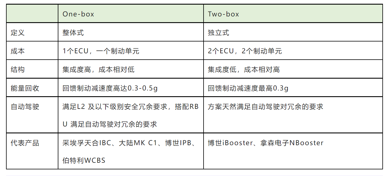
However, it should be pointed out that the One-box scheme also has disadvantages. Although it has significant cost and weight advantages compared to the Two-box scheme in advanced driver assistance systems, for autonomous driving systems, the Two-box scheme can meet the requirements for redundancy of the line control brake system. When a single failure occurs in the master brake system, the backup brake system needs to ensure that the vehicle can still enter a safe state (such as parking on the side of the road). However, the One-box scheme obviously cannot complete this task independently. Therefore, the One-box scheme needs to be supplemented with an independent braking unit RBU (Redundant Brake Unit) to form a Two-box scheme that can support brake redundancy. At this time, the advantages of cost and weight are not obvious.Comparison between One-box and Two-box:
This article is a translation by ChatGPT of a Chinese report from 42HOW. If you have any questions about it, please email bd@42how.com.