Author: Xu Liang
Positioning is the foundation of high-level autonomous driving. However, achieving high-precision positioning under various working conditions is challenging for features such as high-speed NOA and urban NOA. A common problem is: how precise should the positioning be for high-speed NOA and urban NOA, and how precise should IMUs, inertial navigation systems, and sensors be?
With these doubts, I interviewed many industry experts.
The answer to the first question is more consistent: high-speed NOA only needs to achieve lane-level/dm-level positioning to recognize which lane the vehicle is in. For urban NOA, since the lanes are relatively narrow, especially at intersections, lane changes often occur, such as two lanes becoming three or four lanes. To maintain the lane without crossing the lane marking, the positioning accuracy needs to reach the cm-level.
Regarding the second question “how precise should IMUs, inertial navigation systems, and sensors be,” the conclusion reached through discussions with industry experts, including the author, is uncertain, because the final positioning accuracy is the result of matching and fusion of multiple sensors such as a combination of navigational maps, wheel-speed sensors, visual sensors, LiDAR, and millimeter-wave. As long as the fusion positioning accuracy satisfies the requirements, there are no mandatory accuracy requirements for each part.
The following figure shows several components of fusion positioning.
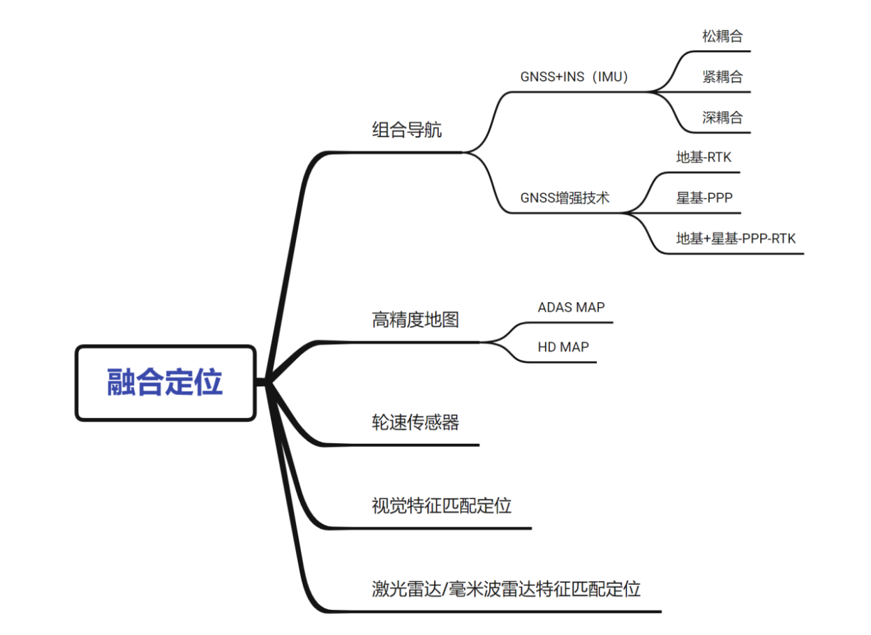
In general, “combination navigation” refers to the combination of two or more non-similar navigation and positioning systems, such as data fusion of GNSS, IMU, wheel-speed sensors, LiDAR point cloud information through an algorithm.
Due to the excellent complementary effect of GNSS and IMU, that is, GNSS supplements the cumulative error problem of IMU inertial system, and IMU effectively compensates for the instability and interference of the GNSS satellite system. Therefore, this “golden partner” is also known as the best combination navigation solution. Therefore, when people generally refer to “combination navigation,” they usually mean GNSS+IMU. Unless otherwise specified, the “combination navigation” mentioned below refers to GNSS+IMU.The main focus of this article is on the following issues —
Why Does GNSS Need Dual-Frequency?
Currently, mainstream GNSS/RTK solutions in China support dual-frequency and multi-constellation.
Multi-constellation refers to the GNSS receiver’s ability to receive signals from various navigation systems, such as China’s Beidou, the United States’ GPS, and Europe’s Galileo. Domestic GNSS receivers typically support both Beidou and GPS.
Dual-frequency means that there are two carrier frequency bands for each navigation system, such as two frequency bands for Beidou and GPS, respectively. Dual-frequency significantly increases hardware and computing costs.
So, what is the purpose of dual-frequency?
After communicating with industry experts, the answer is two-fold: on the one hand, two carrier frequency bands can serve as redundancy, and on the other hand, dual-frequency can achieve higher positioning accuracy.
Ionospheric error accounts for a significant portion of GNSS measurement errors, and dual-frequency carrier wave can utilize the correlation between time delays of electromagnetic waves with different frequencies caused by the ionosphere, which can eliminate most ionospheric errors and greatly improve satellite positioning accuracy. This is something that single-frequency GNSS cannot achieve.
The founder of a certain integrated navigation company mentioned on a forum that the positioning accuracy of single-frequency RTK can reach a 95% probability within a circle with a radius of 0.4 meters (that is, the concept of CEP), while dual-frequency RTK can achieve a 95% probability within a circle with a radius of 0.2 meters. It can be seen that dual-frequency is very important.
Satellite-Based Augmentation Systems (SBAS) and Ground-Based Augmentation Systems (GBAS)
In addition to ionospheric error, GNSS positioning errors also include satellite-related satellite orbit errors (ephemeris errors), satellite atomic clock time errors, tropospheric errors, errors caused by multi-path effects of carrier waves reflected by the earth’s surface, and receiver clock errors related to the receiver.
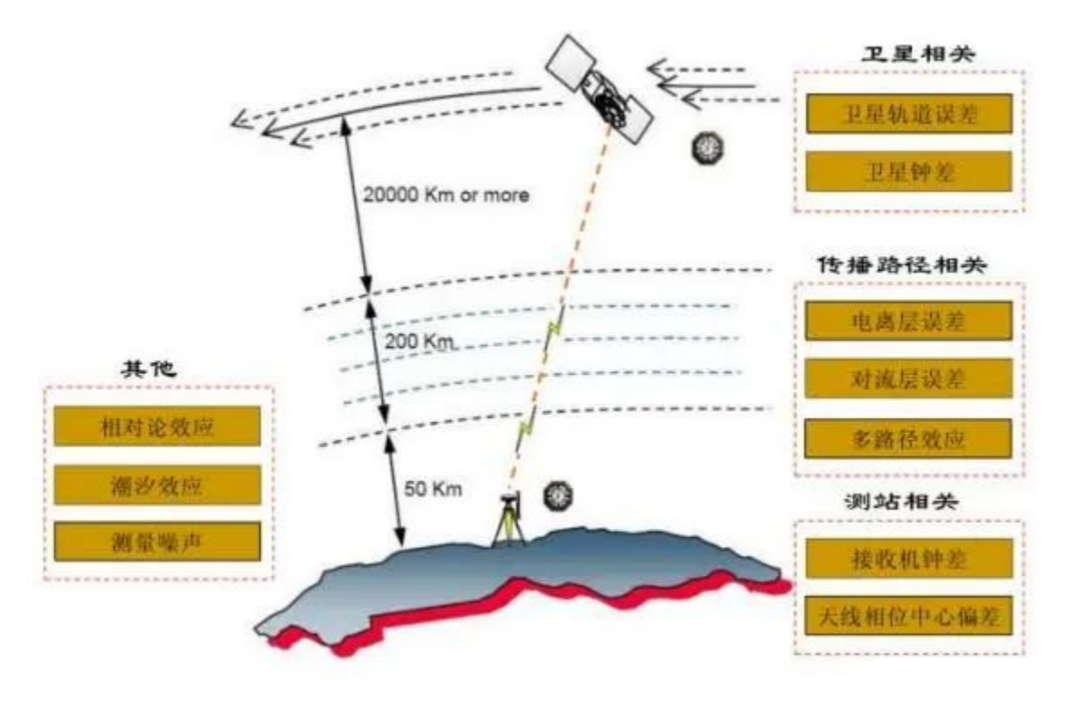 To improve positioning accuracy and minimize errors, in addition to the dual-frequency carrier band mentioned earlier, there are other enhancement methods, which can be categorized into satellite-based augmentation and ground-based augmentation based on their principles.
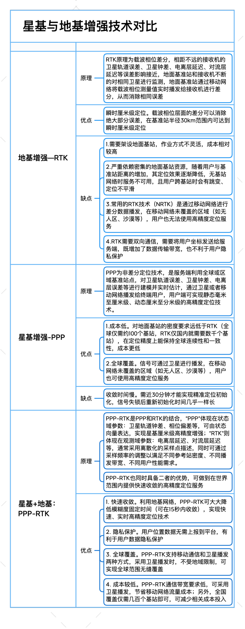
Among them, the most widely used and representative enhancement methods are ground-based Real-Time Kinematic (RTK), satellite-based Precise Point Positioning (PPP), and a combination of both called PPP-RTK. The specific technical introductions and advantages and disadvantages are shown below:
The following figure compares these three modes from three dimensions: convergence speed, positioning accuracy, and coverage area:
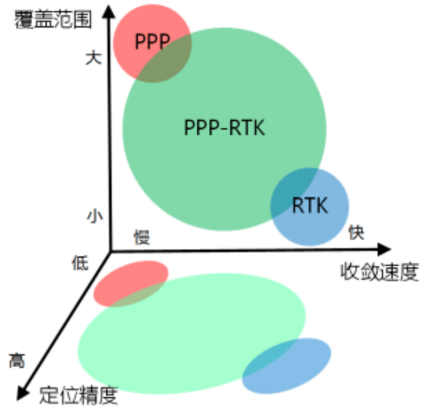
PPP-RTK, as a strong combination of RTK and PPP, not only has the advantages of high accuracy and fast convergence of RTK, but also the global coverage of PPP.
In addition, compared with RTK, PPP-RTK is more in line with functional safety requirements. On the one hand, PPP-RTK is not constrained by ground base stations and mobile network coverage (can be broadcasted through satellites); on the other hand, compared with RTK, which packages the positioning error as a “black box” through differential and does not distinguish individual error sources, PPP-RTK models and estimates each error item globally. Its signal integrity enables it to confirm the error state of each signal and identify whether the signal is convergent, usable, and detectable, thereby meeting the requirements of functional safety to analyze risk factors one by one.## Is PPP-RTK more cost-effective than RTK?
Although PPP-RTK requires far fewer ground stations (a few hundred stations can cover the entire country), if satellite signals are used, it requires renting satellites or launching low-orbit satellites like Qianxun Beidou. It is said that renting a satellite is very expensive (about 10-20 million RMB per year per satellite), and if global coverage is required, multiple satellites need to be rented, and these costs will be included in the service fee.
However, according to the author and several industry experts, the cost of PPP-RTK is not much different from N-RTK. If satellite broadcasting is not used, the cost of PPP-RTK would be even lower.
Many industry experts believe that PPP-RTK is the future trend. It is reported that several pre-installed production projects in China have already used PPP-RTK technology.
Interestingly, Qianxun Beidou, which has already invested heavily in ground-based infrastructure, is also promoting PPP-RTK to its automotive customers (according to the Qianxun website, Qianxun has built more than 2,800 ground enhancement stations). Is this influenced by the strategy of its competitors and is forced to catch up?
If they switch to PPP-RTK, will the resources invested in the early-stage ground-based infrastructure be “wasted”?
According to a senior practitioner of a leading location services provider, although theoretically PPP-RTK does not require so many ground stations, it will still be highly dependent on ground-based data in terms of convergence speed and positioning accuracy. Based on the high-density ground-based service, the PPP-RTK has a much faster convergence speed than similar products from less ground-based density location service providers.
Can Low-orbit Satellites Improve Positioning Accuracy?
Recently, Geely’s subsidiary, Qianxun Positioning, launched nine low-orbit satellites for high-precision positioning in intelligent driving, while Tesla’s “Starlink” also uses low-orbit satellites for global coverage. So, can low-orbit satellites really improve positioning accuracy?
Experts generally agree that low-orbit satellites mainly play a role in communication and have no substantial effect on improving positioning accuracy.
However, although low-orbit satellites cannot improve positioning accuracy, they can indeed enhance satellite signal coverage, especially in partially shaded areas.A senior practitioner believes that in addition to broadcasting enhanced signals, low-orbit satellites can also simultaneously use global satellite navigation systems to broadcast carrier information, thereby increasing the number of navigation satellites that GNSS receivers in a particular area can receive. Previously, some semi-obstructed areas, such as under elevated roadways or near windows in buildings, could not be located accurately or with high precision due to a lack of sufficient navigation satellites. However, with the addition of low-orbit satellites, enough satellites can be received to enhance the availability and reliability of satellite navigation.
Key Indicators and Accuracy Requirements for IMU
As the core component of combined navigation, IMU can provide higher frequency and high-precision signals (generally up to 200Hz) for high-precision navigation calculations within the interval when the GNSS signal is invalid or between updates (the frequency of GNSS signal is 10Hz).
IMU can be divided into a gyroscope and an accelerometer, with the gyroscope outputting the vehicle’s roll, pitch, and yaw angles and the accelerometer outputting the acceleration in three directions.
The cost of IMU increases linearly with the increase of precision since “you get what you pay for.”
The most common question when selecting IMU is: How high-precision should the IMU be to meet the requirements? This relates to the key performance indicators of IMU.
IMU has many device indicators, such as zero bias error, scale factor error, non-linearity error, and so on. The specific indicators and instructions are shown in the figure below.
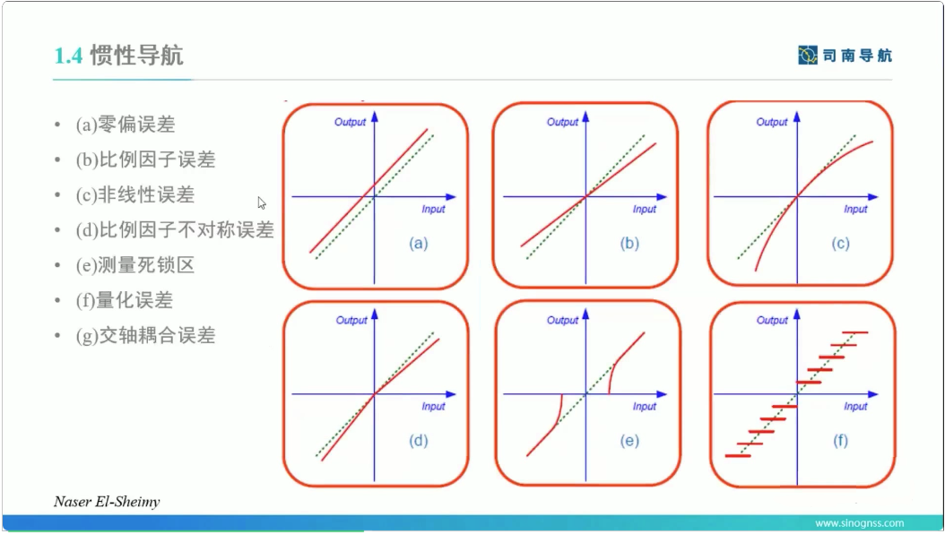
The most critical indicators are two: 1. Zero bias error; 2. Temperature zero bias.
Zero bias error refers to the constant error that occurs when the IMU is in use. Since the error accumulates over time, it needs to be controlled within a certain range. Generally, the zero bias error of the gyroscope is controlled within 2-3 degrees/hour, and the zero bias error of the accelerometer is controlled within 0.003g (3mg).
Temperature zero bias is used to measure the sensitivity of the sensor to temperature. The characteristics of the sensor at different temperatures are different. Generally, the characteristic curve of the sensor is measured, and compensation is performed before leaving the factory to reduce temperature zero bias.According to the understanding, the consistency of temperature compensation will change with the length of use, and there may be differences between the compensation curve after using for several years and the initially calibrated one.
Traditionally, people may be more accustomed to using algorithm indicators to measure IMUs, that is, the deviation between measured values and true values after the vehicle travels 1000 meters in the case of complete loss of GNSS signals such as in tunnels. The industry-standard indicator is around 1/1000 to 1/1005 (1 sigma).
The Evolution Trend of GNSS+IMU Coupling Mode
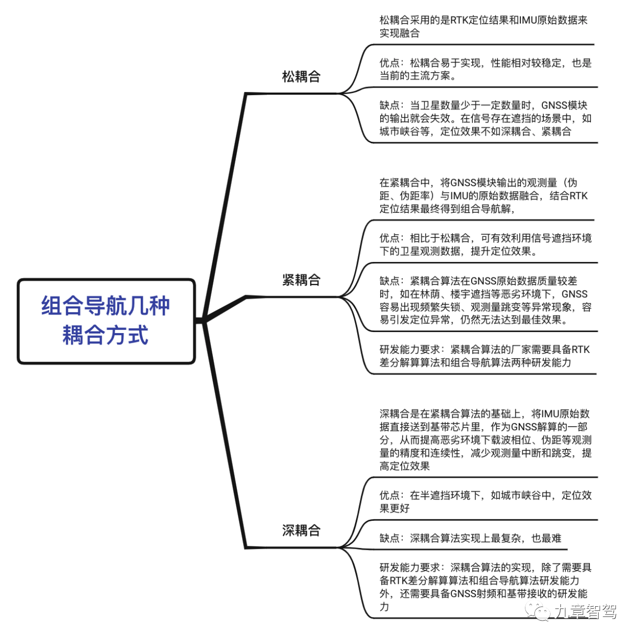
From the bottom-up algorithm level, the combined navigation algorithm can be divided into three types: loosely coupled, tightly coupled, and deeply coupled, and the difficulty of algorithm implementation increases successively.
The introduction of several coupling methods are shown in the figure below, specific details can be viewed from the previous article “Loose, Tight and Deep Coupling in High-Precision Combined Navigation” published by Jiuzhang Intelligent Driving.
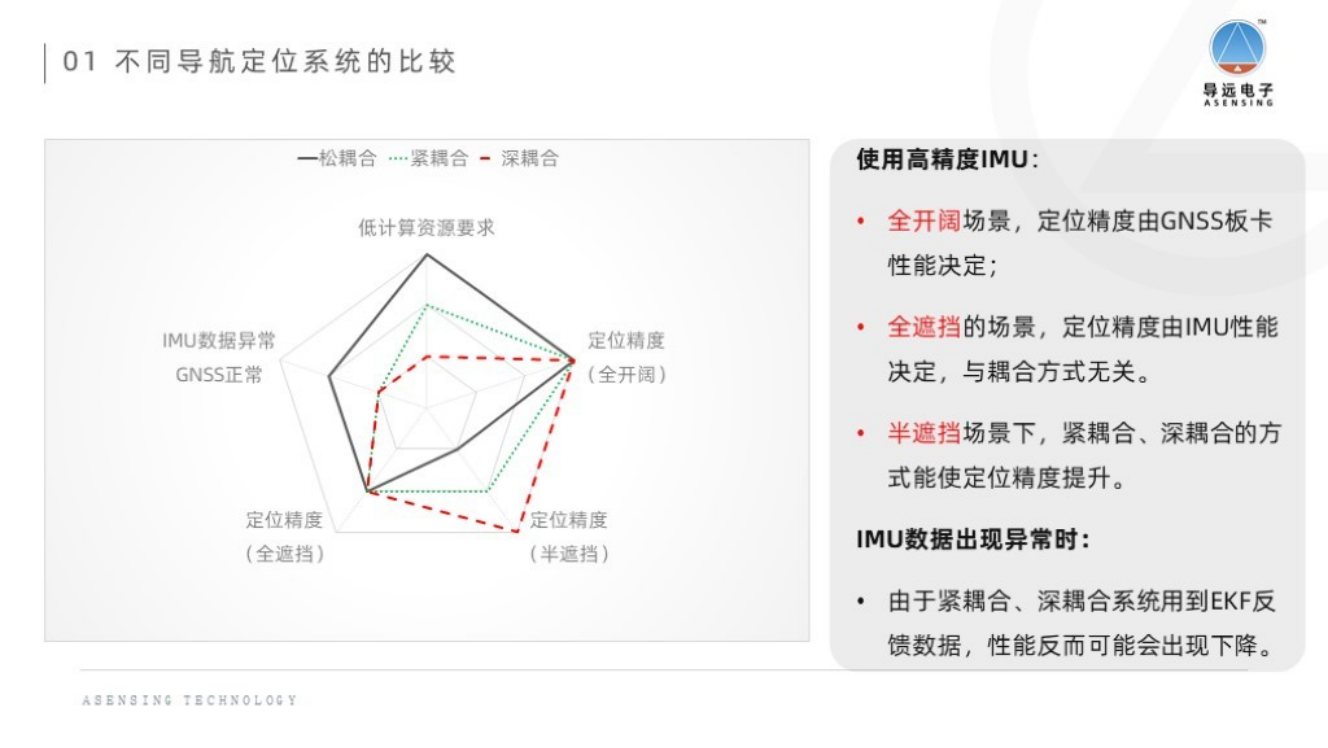
In semi-obstructed scenarios, such as in urban canyons, deep coupling performs the best, followed by tight coupling, and loosely coupled is the worst; in fully open and fully obstructed scenarios, the three coupling methods perform equally well. Details can be seen in the figure below.
When the focus of pre-installed mass-produced passenger vehicles gradually shifts from high-speed NOA to urban NOA, the advantages of deep coupling are reflected.
In exchanges with industry experts, many people also recognize that deep coupling performs better in terms of technical performance. So, will deep coupling become the mainstream trend in the future?
Opinions are mixed within the industry. However, Li Qingjian, Vice President of Spatiotemporal Research and Development at GAC Technology, believes that from the perspective of the development trend of autonomous driving domain control, the game between automakers and suppliers, and the mode of integrating domain control, combined navigation algorithms will exist in the form of domain control algorithms.## Trends of integration in integrated navigation
In the deeply coupled mode, the domain control form becomes more difficult to implement, and tight combination will become the current feasible algorithm. In the future, the centralized positioning of satellite navigation, inertial navigation, and integrated navigation algorithms may become a thing of the past, if the OEMs do not have sufficient development capabilities for the deep coupling algorithms. Multiple source fusion positioning such as maps, perception, etc. will be the focus.
Although some car companies are developing their own integrated navigation algorithms, more OEMs will choose an integrator to integrate satellite navigation, inertial navigation, and integrated navigation algorithms together. This is commonly known as the “P-Box” (Positioning Box). Some of them will also integrate high-precision maps, called “Map Box” (HD MAP BOX).
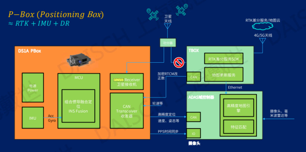
It is generally believed in the industry that the positioning box and the map box are only transitional products. With the gradual maturity of the domain controller technology and the evolution of the centralized integrated architecture, the domain controller integrated integrated navigation module will become the mainstream trend, integrating the integrated navigation algorithm, GNSS, and IMU modules into the domain control, or integrating them with other devices.
Integration has many advantages:
1. Reduce costs. At present, the common practice of positioning box suppliers is to purchase GNSS modules and IMU modules, and place the integrated navigation algorithm in an independent MCU, all integrated in the positioning box. In contrast, integrating the integrated navigation algorithm into the domain controller can save an independent MCU.
2. Improve data exchange efficiency. Integrating the integrated navigation algorithm into the domain controller can reduce the delay in data exchange between the positioning module and other algorithm modules.
3. Convenient deployment. As the integration degree becomes higher and higher, GNSS and IMU are gradually evolving from device level to board level and chip level. Compared with an independent positioning box, it is more convenient to integrate them into other devices, with fewer connecting wires.So, will the integration of combined navigation into the domain controller become the mainstream trend in the future?
After communicating with numerous industry experts, the author found that although many automakers have chosen to integrate the IMU and GNSS modules into the domain controller, there are still many engineering challenges.
The biggest challenge comes from the IMU’s high requirements for installation location and environment.
Firstly, the IMU has a high requirement for installation location. When using the IMU, the autonomous driving system assumes that the IMU’s posture and acceleration represent the state of the whole vehicle. Therefore, the best installation position for IMU is the center position of the rear axle line. Some industry experts pointed out that whether to integrate the IMU into the domain controller depends on the position of the domain controller. If the position is not suitable, it is not suitable to integrate the IMU into the domain controller.
In actual operation, if the position is not suitable, the installation position can be calibrated with the ideal position and then can be used after coordinate transformation. However, this conversion process may cause loss of accuracy of some components.
Secondly, the IMU is very sensitive to temperature changes, so the temperature change at the installation location should not be too large. Inside the domain controller, due to the high-power SoC, the temperature change is larger, which may affect the measurement accuracy of the IMU. Although it will be calibrated by the temperature compensation curve before leaving the factory, the temperature compensation curve mentioned earlier may change with time, which may increase errors. (Of course, some experts also provided feedback that, according to the feedback from projects that have been mass-produced so far, the impact of this error is not significant.)
Thirdly, the IMU has high requirements for the flatness and stiffness of the installation surface. The domain controller has a large PCB area and insufficient rigidity, and the bending deformation during the processing will also affect the performance of the IMU. The vibration during the operation of the domain controller will also bring additional noise. This can be optimized by adjusting the installation position and locally increasing the rigidity.
The installation position of the GNSS module also needs to consider convenience in layout and integration, such as integrating the GNSS module with V2X and T-Box.
An industry expert believes that after modularization, the GNSS module has a small enough size and can be attached anywhere. Generally, for convenience of layout, it will be placed in a position closer to the GNSS antenna. As the GNSS antenna is related to satellite positioning and search, it will be placed in a peripheral position and generally integrated with other antennas, such as 4G antennas, radio antennas (shark fin), etc. If the GNSS module is placed in the domain controller without considering the location, the GNSS antenna needs to be connected to the domain controller, and the connection line may be longer, which may affect the time accuracy.## The Coexistence of Standalone Boxes and Integration Trend May Be Long-Lasting
In contrast to the trend of integrated positioning boxes, positioning box suppliers hope to maintain the form of standalone boxes that can access more signals and continue to improve positioning accuracy. For example, the mapping box launched by DaoYuan not only integrates GNSS, IMU, wheel speed, and high-precision maps, but also further integrates ADAS cameras, allowing for visual fusion positioning to further improve positioning accuracy and reliability. It is claimed that it can achieve lateral error of less than 0.2 meters and longitudinal error of less than 2 meters with a 95% confidence interval.
However, an engineer responsible for positioning at a newly emerged automaker said that they completely reject the idea of leaving the visual fusion positioning to the positioning box supplier. On the one hand, it is difficult to distinguish responsibilities as it is related to the issue of who integrates whom. On the other hand, they also do not recognize the image processing capabilities of the positioning box suppliers, and this also involves the issue of wasting computing power resulting from image processing taking place twice.
Regarding this behavior, a senior executive of a combination navigation supplier believes that at present, traditional carmakers or weak R&D capabilities of carmakers prefer suppliers to provide an overall solution for positioning, such as integrated satellite navigation, inertial navigation, high-precision maps, and even visual fusion positioning for convenient cost control and improved reliability in mass production of advanced intelligent driving.
Integrating the combination navigation into domain control requires a high demand for the R&D capabilities of car manufacturers, as well as algorithms for perception and decision-making. Therefore, if these requirements cannot be met, it is a quick and high-integrated-reliability solution to leave the positioning task to third-party suppliers.
Although the integration of positioning modules is a trend in the long run, standalone positioning boxes may still exist for a long time to come.
Improving Fusion Positioning Algorithm Can Reduce Requirements for Key Components of Combination Navigation
As previously mentioned, combination navigation is actually part of the autonomous driving positioning system, and the final system relies on fusing various data for positioning.
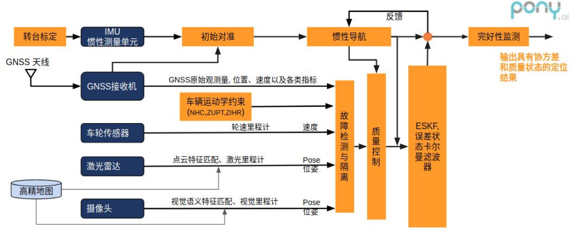 The data commonly used for fusion positioning includes GNSS, IMU, RTK (or PPP-RTK), high-precision maps, wheel speed sensors, LiDAR, cameras, etc. The final positioning accuracy depends on the fused positioning accuracy.
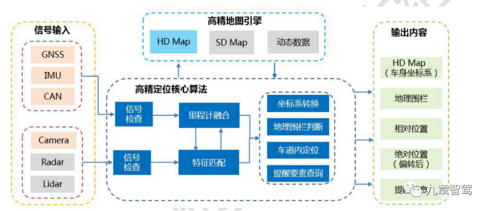
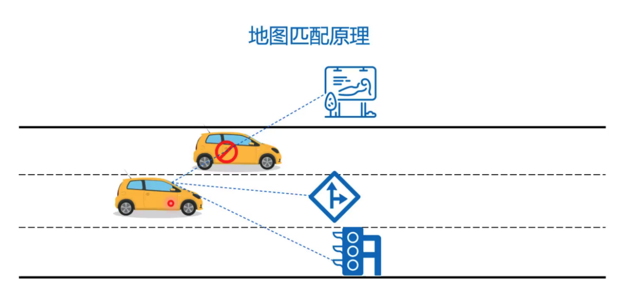
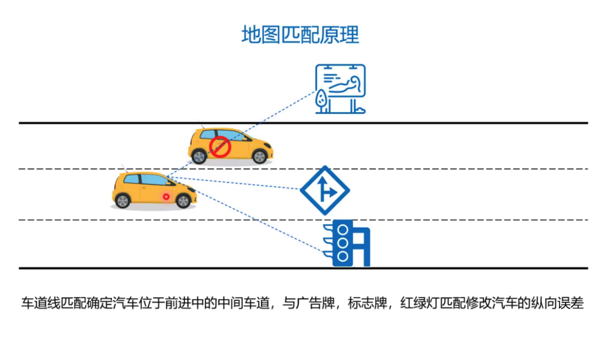
It is worth mentioning that besides GNSS-based absolute positioning, it is also possible to achieve lateral relative positioning based on the position of the lane lines observed by the camera, and to use key features observed by LiDAR, cameras, millimeter-wave radar, etc. (such as signs, traffic lights, etc.), and high-precision maps to achieve longitudinal relative positioning (SLAM) through matching.
Indeed, if the fusion positioning algorithm is good enough, it can reduce the requirements for key components of integrated navigation (such as IMU accuracy).
Many experts have stated that the high precision of the IMU is mainly to meet some positioning degradation scenarios-such as tunnels. In the tunnel scenario, only the GNSS values at both ends can be relied on for absolute positioning, and only the IMU can be relied on for track estimation in the middle of the tunnel.
However, there are also solutions. An expert from Baidu Apollo mentioned in a sharing session that on the one hand, the requirement for absolute accuracy in the tunnel is not high, and the curvature of the road will not change too much; on the other hand, more features, such as textures, can be introduced to assist positioning.
Some experts also pointed out that lateral positioning can be achieved using vision and millimeter-wave radar in tunnels, and as for the accuracy of longitudinal positioning, “it’s not that important”.
Can fusion positioning get rid of the reliance on high-precision maps?In addition to reducing the requirement for combined navigation, a certain L4 level company that has entered the front-loading production stage has also revealed that it is exploring a solution for implementing high-speed NOA function that does not rely on RTK.
In fact, high-precision positioning is used in conjunction with high-precision maps. If RTK is not necessary, do we still need high-precision maps?
Many people in the industry believe that high-precision maps are a “crutch” in autonomous driving. High-precision maps are not affected by the environment and are not limited by distance. They can assist perception as super-distance perception input and effectively compensate for sensors. If the “crutch” is discarded now, there may still be some problems, such as encountering obstacles from large vehicles and fuzzy lane lines in real-life scenarios. Sensors are also often limited by distance and environmental factors.
According to feedback from some industry experts, it is difficult to achieve lane-level positioning without high-precision maps (relying solely on navigation maps), because the lane information is missing from the navigation map and only the relative positioning can be done through recognition of visual lane information. When encountering road signs and lane line obstructions at intersections, it is difficult to recognize the road topology structure, and decision-making and planning errors are likely to occur.
In addition, when driving on small-radius curved ramps, it will be difficult to control the vehicle’s lateral and longitudinal movements because the navigation map lacks curvature information, and there may be a feeling of jerking.
From these aspects, a certain degree of “high-precision maps” is still needed, but this so-called “high-precision map” may not be as accurate or comprehensive as the precision provided by present map providers. It may be a road semantic map overlaid on the navigation map, which can be called “Navigation Map Plus”.
In this regard, the memory parking function provides a good paradigm. Before the memory parking function is turned on, it is necessary to construct maps and memory routes, and then perform location decision-making and planning based on the constructed maps.
Therefore, some solution vendors have proposed the memory driving function. For urban commuting routes, the map and route memory is completed by repeated driving several times. That is, a local constructed semantic map “Navigation Map Plus” is overlaid on the navigation map, and location, decision-making and planning are performed based on this map, which achieves point-to-point navigation assistance in the city without relying on high-precision maps.
This can to some extent achieve a “standalone” version of the map. And if further developed, what if locally constructed maps are shared to the cloud? Wouldn’t this become a crowdsourcing map?
In fact, XPeng Motors said that it already supports the parking lot memory parking map-sharing function. After learning the route, the user can choose to share the route. After cloud-side review, the user can manage and share the route on their smartphone. Upon arriving at the destination parking lot, the user can use other users’ uploaded or official recommended parking routes, which to some extent, has turned the parking lot into a “crowdsourcing” map.# Driving and Parking: Different Functions but Same Direction in Solving Map Issues
References:
- White Paper on High-Precision Maps for Intelligent Connected Vehicles
- Pony Tech | Pony.ai Map and Location Series: The Importance of Integrated Navigation Technology in Autonomous Driving
- Special Topic Research for Navigation Industry: Integrated Navigation Welcomes the Era of Autonomous Driving
- Sinan Navigation Technology Front Line: Live Replay | Integrated Navigation and Intelligent Driving
- Beiyun Technology Launches Vehicle-Grade Integrated Navigation Unit to Boost Mass Production of Autonomous Driving Vehicle Models
- Daoyuan Electronics: What Kind of IMU is Needed for Tightly-Coupled Automatic Driving Location?
- Eleventh Organization: GNSS (I), the “Umbrella” of Autonomous Driving Location Team
- Eleventh Organization: GNSS (II), the “Umbrella” of Autonomous Driving Location Team
- Academic Exchange | From RTK, PPP to PPP-RTK
- Memory Parking Route Sharing and New Function Guide – XPeng Community
This article is a translation by ChatGPT of a Chinese report from 42HOW. If you have any questions about it, please email bd@42how.com.