Exploring Network Management in Automotive Industry
Author: Struggling Labourer
Preface: First of all, let me ask you a few questions:
-
Why do we need to introduce network management? Isn’t it great to have ignition and shutdown at the same time?
-
Do you know the different types of ECU nodes available on a vehicle?
-
How do ECUs maintain synchronization during the startup of the car?
-
How do ECUs work collectively during a shutdown?
-
After the car is turned off, which ECU will continue to function?
In this article, we will explore and answer these questions together. To make it easier for everyone to understand, below is the outline of this article:
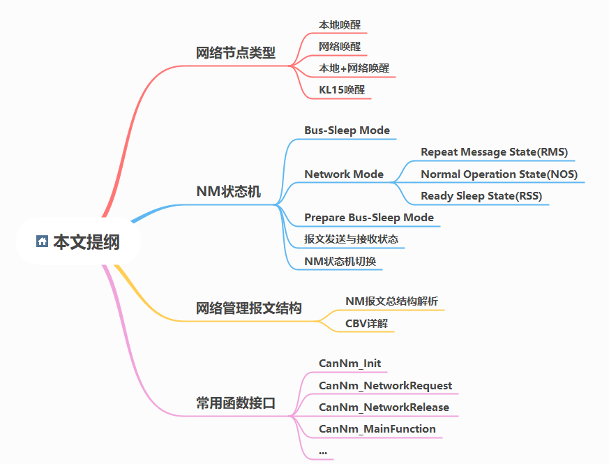
Node Types on the Network
There are thousands of ECU nodes on automobiles. It is not practical to have all ECUs working normally when ignition is turned on. Rather, only the ECUs related to the requested functions by the user should be activated. Otherwise, it will consume unnecessary battery power.
In order to better utilize the energy of the entire vehicle, prevent unnecessary waste of batteries, network management (NM) can solve such problems very well, and maximize the efficient use of the vehicle’s battery energy, save the cost of car use, and extend the battery life.
Although there are various types of network buses on a car, such as CAN, FlexyRay, Lin, Ethernet, etc., the basic principles are similar. This article will explain the NM of the most common CAN bus, and we can learn about the NM of other buses in AUTOSAR with the same idea.
Generally speaking, based on the wake-up method, we can divide the ECU network node types into two categories: local wake-up and remote wake-up.
Local Wake-up: Wake-up source comes from the self-module, such as KL15 hardline wake-up or hardware sensor perceptual wake-up, etc.
Remote Wake-up: Wake-up source comes from the network message where the node is located, and the node can be in a completely sleep state with no static consumption.
Based on these two wake-up modes, we can combine the following four sub-wake-up modes. The power supply methods for each mode are shown in the following figure:
Local Wake-up Nodes Only
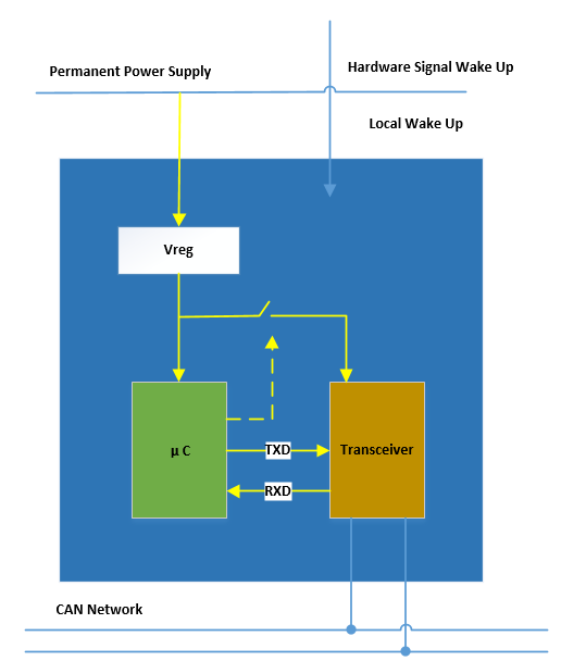
Features: The ECU always maintains the after-running state. When the local wake-up source is detected, network communication will be initiated.
Network Wake-up Nodes Only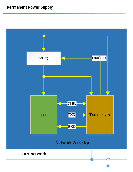
Features: Vreg will only supply power to the chip to wake up the ECU when the Transceiver detects a change in the bus level or receives specific messages.
Local + Network Wakeup Node
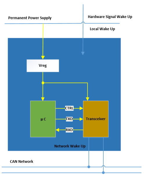
Features: The ECU remains in After-Running Mode. When it receives signals from either the local wakeup source or the network wakeup source, the ECU will start up.
KL15 Wakeup Node
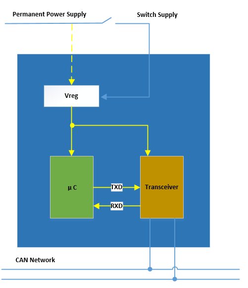
Features: The ECU only wakes up when the Power Supply is connected to the ECU, for example, the KL15 startup wakeup.
NM State Machine
This article does not focus on discussing the local wakeup method in detail since it is a custom wakeup method defined by the supplier, and is straightforward without the participation of other ECU nodes, nor does it affect other ECU nodes.
However, network wakeup is based on Network Management messages to coordinate the network’s “sleep and wake up together” mode. It adopts a distributed direct network management method to send network management requests and network management states required by its own nodes, and receives network management requests and states from other ECU nodes on the network.
Therefore, it is necessary to further study the state types of the NM state machine and their state transition relationships. The state types of this state machine can be divided into the “Three Major and Three Minor”. The “Three Major” refers to Bus Sleep Mode, Network Mode, and Prepare Bus-Sleep Mode, while the “Three Minor” refers to the three sub-states under Network Mode: Repeat Message State, Normal Operation Mode, and Ready Sleep Mode.
Bus Sleep ModeWhen there is no remote wake-up or local wake-up request, the Controller of ECU should switch to Sleep mode, where the current consumption will be reduced to the lowest level. This Mode is the start-up state when ECU is turned on or the final state when ECU is in sleep.
In this mode, NM messages and application messages should be prohibited from being sent, but can be awakened by messages on the network.
It should be noted that when the Transceiver supports and enables wake-up of specific frames, the ECU will only be awakened normally when specific NM messages are received. Otherwise, it will always be in a sleep state, without being interfered by any other messages on the network.
If the Transceiver does not support wake-up of specific frames, any message on the network can wake up the ECU. If the wake-up condition is not met, it will go back to sleep mode again. This “alternating sleep and wake-up” is a typical feature of a Transceiver that does not support wake-up of specific frames. Of course, if NM on the entire vehicle can operate normally, this “alternating sleep and wake-up” will not occur frequently, and it usually only appears more when testing.
Network Mode
Once entering the Network Mode, timer TNMTimeout will start, and as long as NM messages are successfully received from or sent to the bus, the timer TNMTimeout will be reset.
This mode is further divided into the following three sub-states: RMS, NOS, RSS.
-
Repeat Message State (RMS)
-
This state ensures that when the state machine of the ECU switches from Bus-Sleep Mode or Prepare Bus-Sleep Mode to Network Mode, it can be timely discovered by other ECU nodes on the network, which means telling other ECUs, “everyone look, I’m online, please guide me more!”
-
When successfully entering the RMS state, this node will re-send the NM messages and start timer TREPEATMESSAGE, while application messages need to wait until the first network management message is sent before sending.
-
Of course, the first NM message can be delayed by configuring parameter MSGCYCLEOFFSET to reduce the bus load during the same time. This configuration parameter is usually set at 0 and adjusted appropriately based on test results.
-
This node will stay in this state until timer TREPEATMESSAGE times out, otherwise it will leave this state.
-
There are also two sub-states in this state:- NM Immediate Transmit State
In this mode, the ECU aims to quickly wake up the entire network, and the node will send NM messages at a cycle of TNMImmediateCycleTime, with the number of sends determined by the configuration parameter NImmediateNMTIMES. Each successful send will subtract 1 from this parameter until it reaches 0, and the sub-state will then exit.
- NM Normal Transmit State
In this mode, the ECU node sends NM messages at the normal message cycle TNMMessageCycle.
- Normal Operation State (NOS)
As long as the ECU node needs to communicate on the network, it will continue to operate in NOS mode. NM message sending in this state will occur at the cycle of TNMMessageCycle, and each successful send or receive, or when the timer NM-Timeout times out, will reset the timer NM-Timeout.
NM messages and application messages should be sent and received normally in this state.
- Ready Sleep State (RSS)
In this mode, the ECU node should stop sending NM messages. Each time it successfully receives an NM message from the network, the timer TNMTIMEROUT will be reset. Once TNMTIMEROUT times out, the ECU will leave this state and enter the Prepare Bus-Sleep state.
Prepare Bus-Sleep Mode
Once in this mode, the timer TWAITBUSSLEEP will start. NM message sending is prohibited in this mode, but NM messages can be received. Application messages that are already in the buffer can generally continue to be sent, but the bus should eventually become silent, and the state of the ECU’s controller should be in operational mode. Once TWAITBUSSLEEP times out, the ECU will enter the Bus-Sleep phase.
Passive Mode
In this mode, only NM messages are received, but no NM messages are sent. This mode can be configured, but it should only exist in development or debugging processes. It should be prohibited in software for formal SOP.
Message Sending and Receiving StateTranslate the following Chinese Markdown text to English Markdown text while preserving the HTML tags within the Markdown. Only output the corrected and improved parts of the text without writing any explanations.
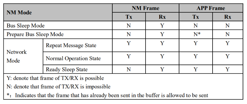
During the testing process, it is necessary to test the reception and transmission of NM messages and APP messages for each state of network management. As shown in the figure below, it reflects the message transmission and reception status under different NM sub-states.
-
During the Bus-Sleep phase, only NM wake-up messages are received, and no messages are sent;
-
During the Pre-Bus-Sleep phase, only NM messages are allowed to be received. In addition, APP messages that have already been in the sending buffer should be stopped immediately after being sent;
-
In Network Mode, except for the Ready Sleep phase, NM messages and APP messages can be sent and received normally in other phases;
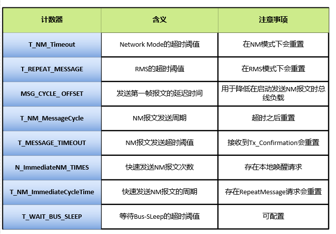
Summary of Time Parameters in State Machine
Considering that various timers are used in the switching process of each sub-state of network management, in order to facilitate the explanation of the subsequent state machine switching and table lookup in the future, the relevant parameters are summarized below for reference.
NM State Machine Switching
The NM state machine is the core of the entire network management system. As mentioned above, the NM management state machine is divided into three modes: Bus-Sleep, Pre-Bus-Sleep, and Network Mode.
Among them, Network Mode can be divided into three sub-states: Repeat Message State, Normal Operation State, and Ready Sleep State.
Among them, Repeat Message State can be further divided into Immediate Transmit State and Normal Transmit State.
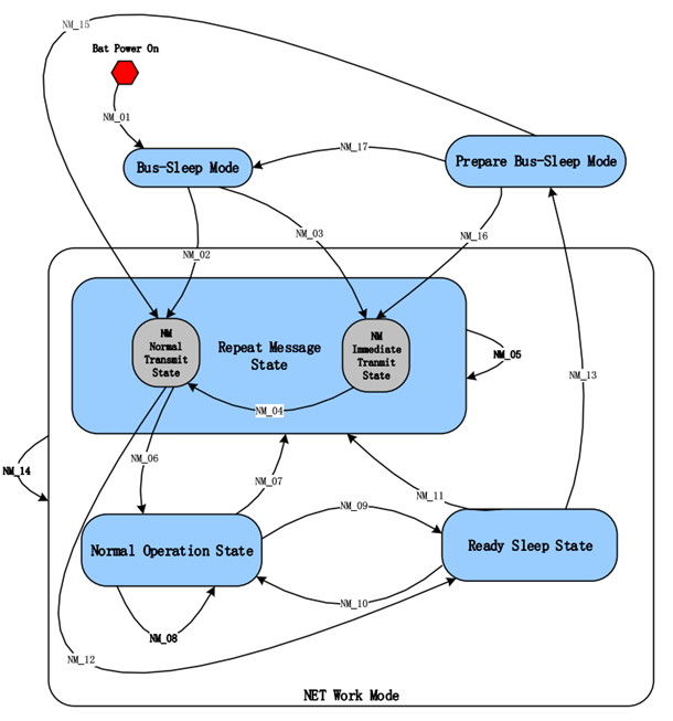
As shown in Figure 7, the switching paths of each state will be explained one by one based on the following state switching paths.
Wake-up sources can generally be divided into local wake-up sources and remote wake-up sources.
- Local wake-up source: mainly refers to self-requests based on internal timers, sensors, buttons or hard-wired connections or internal states.- Remote Wake-up Source: This mainly refers to the NM messages or other related signals from the network, such as ignition switch signals.
Before the ECU is awakened, the internal state machine of the software should fully implement the reliability check of the wake-up source. If the check fails, Network Mode should be prohibited.
In most cases, ECUs that need to support NM are always connected to KL30. In this case, whether the ECU is started (there is static current consumption) depends on whether there is any message on the network or a specific NM message exists. It should be noted that the specific NM message wake-up method depends on whether a Transiver that supports specific frame wake-up is used.
- NM_01 (System Initialization):
When the system KL30 is started or receives a wake-up signal from the network, the system initialization will be performed. During the initialization process, CanNM_Init will be executed to implement the initialization of NM. If the wake-up condition is not met, the ECU will remain in the Bus-Sleep stage until the conditions for sleeping are met or it is normally awakened.
- NM_02 (Bus-Sleep to RMS):
When the ECU is in the Bus-Sleep stage and receives a valid NM message, it will enter the Normal Transmit State. After entering this stage, the ECU will transmit the message according to the TNMMessageCycle cycle before the TREPEATMESSAGE timeout, and the TMESSAGETIMEOUT will also be activated.
- NM_03 (Bus-Sleep to RMS):
When the ECU is in the Bus-Sleep stage and there is a local wake-up request, the ECU should actively activate the network and enter the Immediate Transmit State stage, while setting the Active Wake up bit to 1 in the NM message to be sent.
In this state, the network management message should be sent according to the TNMImmediateCycleTime period and the NImmediateNMTIMES times.
- NM_04:
When the NImmediateNMTIMES equals 0, the NM state will transition from Immediate Transmit State to the Normal Transmit State.
-
NM05 (RMS to RMS):During the RMS phase, if TNMTIMEROUT times out, the current NM state will not change, but TNMTIMEROUT will be reset. When TMESSAGE_TIMEOUT times out, the corresponding exception function will be called to notify the upper layer for processing.
-
NM_06(RMS to NOS):
During the RMS phase, when TREPEATMESSAGE times out, the ECU needs to continue to maintain the need for network communication by calling the CanNMNetworkRequest function to enter the NOS phase, and the ECU will continue to send NM messages according to TNM_MessageCycle.
- NM_07 (NOS to RMS):
In the NOS phase, there are two RMS sub-states that can be reached: the Immediate Transmit State and the Normal Transmit State. If the self-node needs a repeat message, it will enter the Immediate Transmit State. If the received NM has the repeat message bit set to 1, it will enter the Normal Transmit State.
- NM_08 (NOS to NOS):
In the NOS phase, if TNMTIMEROUT times out, the current NM state will not change, but TNMTIMEROUT will be reset. When TMESSAGETIMEOUT times out, the corresponding exception function will be called to notify the upper layer for processing.
- NM_09 (NOS to RSS):
When the sleep condition is met, the ECU will use the CanNm_NetworkRelease function to switch from the NOS to RSS state. NM messages should be stopped in the RSS state.
- NM_10(RSS to NOS):
In the RSS state, if there is a local wake-up request, it can be switched to the NOS state by calling the CanNm_NetworkRequest function.
- NM11 (RSS to RMS):- NM12 (RMS to RSS):
When the ECU is in Normal Transmit State of RMS state under RSS state, it will enter into Immediate Transmit State or Normal Transmit State when a repeat message request is issued from its own node or a received NM message with repeat message bit set to 1, respectively.
- NM_13 (RSS to Pre-Bus-Sleep):
If there is no local or remote wake-up request in RSS state, it will enter Pre-Bus-Sleep stage after the TNMTIMEROUT times out, and at the same time, TMESSAGETIMEOUT is set to 0, and the T_WaitBusSleep timer is started.
- NM_14 (Network Mode to Network Mode):
In Network Mode, TNMTIMEROUT will be reset when an NM message is successfully received or sent, and the behavior of resetting this timer occurs when calling the CanNMRxIndication or CanNMTxConfirmation interface.
- NM_15 (Pre-Bus-Sleep to RMS):
In the Pre-Bus-Sleep mode, if there is a remote wake-up request, it will enter the Normal Transmit State of RMS stage. At the same time, TREPEATMESSAGE is started.
- NM_16 (Pre-Bus-Sleep to RMS):
In the Pre-Bus-Sleep mode, if there is a local wake-up request, i.e., calling the CanNmNetworkRequest function interface to enter into the Immediate Transmit State of RMS stage, the network management message should be sent with a periodicity of TNMImmediateCycleTime according to NImmediateNM_TIMES times.
- NM_17 (Pre-Bus-Sleep to Bus-Sleep):In the Pre-Bus-Sleep mode, if there is no local wake-up or remote wake-up request, the system will enter the Bus-Sleep state. The decision to turn off the power control can be made based on the type of node.
Network Management Message Structure
As an important carrier for transmitting the NM state of the node itself, it is necessary to carefully study the meaning of each bit in the NM message.
Next, taking the CAN NM message as an example, we will analyze the overall structure of the message and the corresponding meanings of each bit, in order to understand the collaborative wake-up and sleep modes of each ECU node.
Analysis of the Overall Structure of NM Message
As shown in figure 8 below, according to the latest official AutoSAR document:
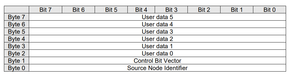
It can be seen from the figure that Byte 0 represents the current node’s Source ID. For example, if the NM message ID sent by the current node is 0x514, then the Source ID is 0x14. Byte 1 is CBV, which carries the current node’s network status and is a very important byte. The remaining bytes are defined as User Data and given to the customer for their own definition, such as defining the current wake-up source, the network management state machine switching process, etc.
Of course, the above definition of message content is only an example given by AutoSAR. Source ID can be allocated to Byte 0, Byte 1 or none, and CBV can also be allocated to Byte 0, Byte 1 or none. The allocation and definition of these byte contents can generally be configured in the BSW toolchain.
CBV Explanation
In view of the importance of CBV, the specific meaning of each bit in its use is explained in Figure 9 below:
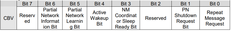
Bit 0: Repeat Message Request Bit
-
0: Indicates that there is a Repeat Message Request.
-
1: Indicates that there is no Repeat Message Request.
Bit 1: PN ShutDown Request Bit (PNSR)
-
0: The NM message does not contain a synchronous partial network management sleep request.
-
1: The NM message contains a synchronous partial network management sleep request.Bit 3: NM Coordinator Sleep Bit
-
0: Not requested to synchronize sleep by the coordinator NM node.
-
1: Requested to synchronize sleep by the coordinator NM node.
Bit 4: Active Wakeup Bit
- 0: Node has not woken up the network and is passively awakened.
- 1: Node has woken up the network and is actively awakened.
Bit 5: PN Learning Bit (PNL)
- 0: PNC learning is requested.
- 1: PNC learning is not requested.
Bit 6: PN Information Bit (PNI)
- 0: PN information is included in the NM message.
- 1: PN information is not included in the NM message.
Of the above bits, Bit 0, Bit 3, Bit 4, and Bit 6 are commonly used and require special attention.
Commonly used function interfaces
To better use the module functions and facilitate debugging, the following important and commonly used functions of the CanNM module are listed in Figure 10.

As for the related knowledge of PNC for this module, due to the limited space, it is not appropriate to go into detail. It will be discussed in a future dedicated chapter, so please stay tuned.
This article is a translation by ChatGPT of a Chinese report from 42HOW. If you have any questions about it, please email bd@42how.com.