
Author | Xi Shaohua
With the increasing number of on-board LiDARs, how to use LiDAR effectively has become crucial, and one of the key points is to process point cloud data properly.
LiDAR point cloud refers to the dataset of spatial points obtained by scanning with a 3D LiDAR device. Each point cloud contains 3D coordinates (XYZ) and laser reflectance intensity (Intensity), where the intensity information is related to the target surface material and roughness, laser incidence angle, laser wavelength, and energy density of the LiDAR.
To further explain point clouds, the author has summarized the relevant parameters and characteristics of point clouds in the table below.
Table: Relevant Parameters of LiDAR Point Cloud
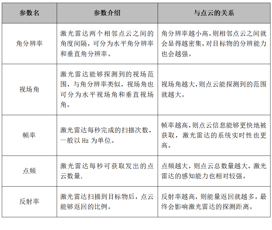
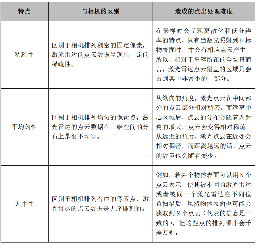
Table: Characteristics of the Point Cloud
From the principle of point cloud acquisition, taking the ToF route of LiDAR as an example, LiDAR point clouds are obtained by emitting laser signals from a vehicle-mounted laser scanning system, collecting the reflected laser signals, and measuring the distance information of the target object through information such as the speed of light and the time from laser emission to return. Then, combined with information such as IMU, odometer, and GNSS, the three-dimensional coordinate information and distance information of the front target objects are calculated.
In addition, in the process of point cloud acquisition and analysis, perception algorithm personnel need to use the characteristics and working principles of the vehicle-mounted LiDAR and combine the relevant parameters such as the angular resolution and field of view of the LiDAR to better utilize the point cloud.
So, what are the specific processing processes and methods for LiDAR point clouds in the vehicle-side processing stage? And how can it be optimized?
Therefore, to verify these issues, the author interviewed Dr. Xu Jian, head of the Tudatong Algorithm, Leon, head of System and Application, Yin Wei, senior manager of SAIC, Tang Qiang, perception algorithm engineer of Zongmu Technology, and experts from Hesai Technology. Here, the author thanks all the experts for their support and has compiled the following series of articles for readers to refer to.The following is the first article in the series of laser point cloud processing.
Specific Process of Laser Point Cloud Processing
After discussing what point clouds are and their features, this article will continue to analyze the processing flow of laser point clouds in autonomous driving. Before that, two points need to be clarified.
First, when laser point clouds are used for perception and positioning, they will be pre-processed and processed differently based on their specific purpose. The application details of point clouds will also differ accordingly.
Tang Qiang said, “When laser radar is used for positioning, the algorithm model requires as much data as possible from the point cloud, and unlike perception, positioning also requires road data such as lane lines or landmarks. They are different from the reflectivity of laser and ordinary road surface reflectivity. Laser radar obtains road data through this way. When laser radar is used for perception, it goes through a preprocessing process and determines an ROI range. Subsequently, it uses the point cloud data from this area to complete the subsequent detection.”
Second, every company will have some differences in the processing flow in the specific application scenario of point clouds based on their own technical solutions. However, most of the processing flows are the same.
To elaborate on the point cloud processing flow in more detail, the author has combined the content of expert interviews with publicly available information to summarize the general process of laser point cloud in autonomous driving applications.
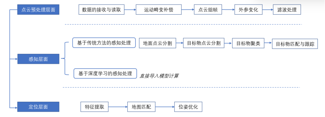
Preprocessing of Point Cloud
1.1 Reception and Analysis of Original Point Cloud Data
(1) Reception of Point Cloud Data
The original point cloud data of the laser radar are all stored in a data packet (pcap). At this point, the data in the data packet are all a sequence of bytes and cannot be used directly.
Taking the 16-line laser radar from Velodyne as an example, the reception of the original point cloud data is mainly in the form of UDP (User Datagram Protocol) that sends data to the network. Specifically, after setting the laser radar on the web side or through the command line, technical personnel will match the IP address of the laser radar with their own UDP port number on the receiving end, and then, they can receive the original point cloud data.## Analysis of Velodyne VLP-16 LiDAR Data
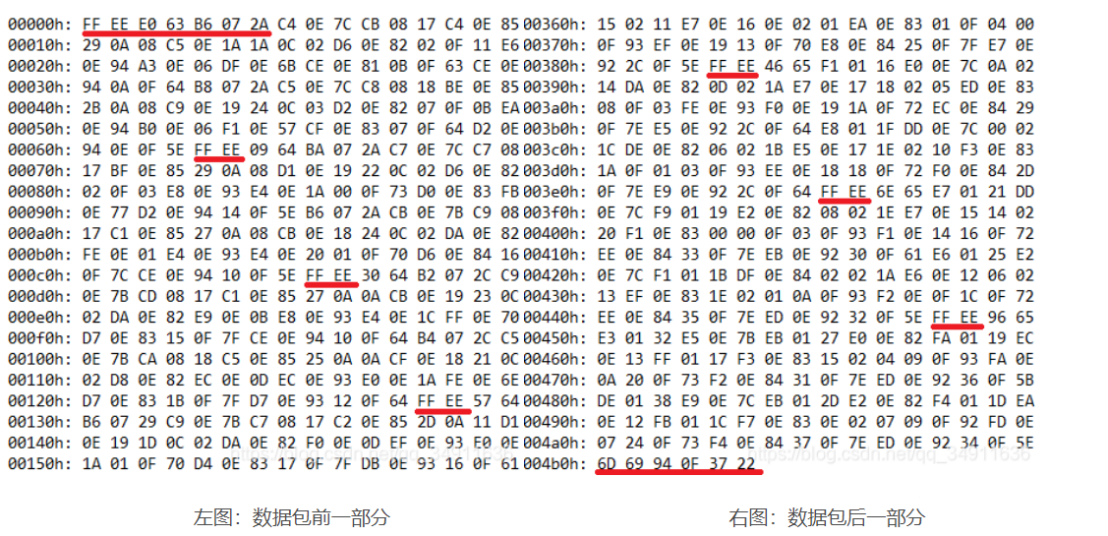
According to the data, the Velodyne VLP-16 LiDAR has 16 laser beams in the vertical direction (-15° to +15°). The data length of each frame is fixed at 1248 bytes, including the first 42 bytes of pre-data packet identification, 12 data packets, 4 bytes of timestamp, and the last two bytes are the LiDAR model parameters.
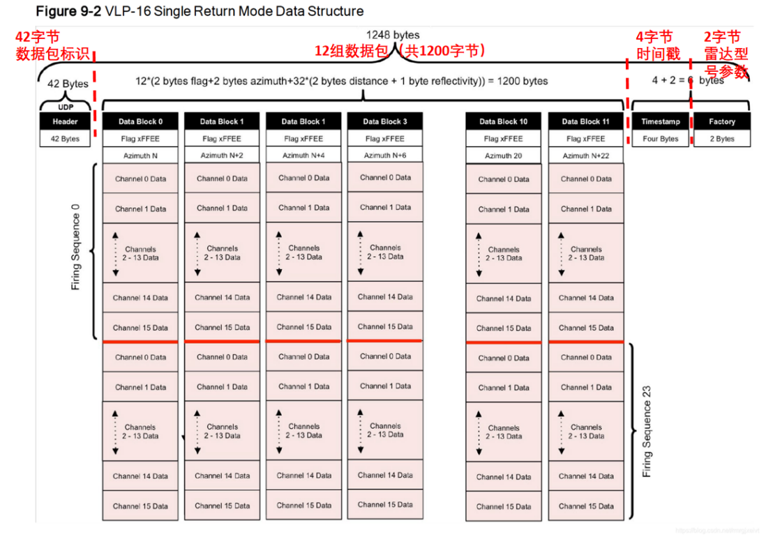
Each data packet contains information about the rotation angle, distance value, and reflectivity intensity of the laser beam. For example, “B6 07” represents the detection range of the LiDAR, and “2A” represents the reflectivity intensity of the laser, but this information is expressed in two bytes and needs to be further parsed.
Parsing of Point Cloud Data (PCD)
The original data in the data packets (pcap) need to be further converted into the Point Cloud Data (PCD) format that can be used by perception engineers.
The PCD format file of point cloud data is a storage format for LiDAR point clouds, and the PCD file is mainly composed of a list of Cartesian coordinates (x,y,z) and intensity values i. Each point cloud has its unique three-dimensional coordinate system and energy reflection intensity.
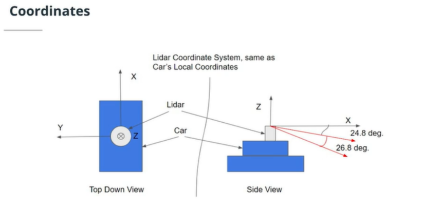
In this coordinate system, the x-axis points to the front of the vehicle, and the y-axis points to the left side of the vehicle. As the coordinate system adopts the right-hand rule, the z-axis of the coordinate points upwards of the vehicle.“`
To illustrate the process of point cloud data parsing, this article takes a frame of point cloud data package from Velodyne-16 LiDAR as an example, and organizes the process based on publicly available information as follows.
Step 1: Calculate the rotation angle value of the laser beam.
For example, the rotation angle of the first line of the first part of the data package in the above figure is 0xE0, 0x63.
a) Reverse the order of the two bytes to hexadecimal 63 E0.
b) Convert 63 E0 to an unsigned decimal as 25568.
c) Divide 25568 by 100 to get 255.68, which is the current rotation angle value.
Step 2: Calculate the distance measured by the 16 laser beams separately.
For example, the distance of the first laser beam in the first part of the data package in the above figure is “B6 07 2A”, where “B6 07” is the distance and “2A” is the reflection intensity.
a) Reverse the distance bytes “B6 07” to “07 B6”.
b) Convert “07 B6” to an unsigned decimal as 1974.
c) Since the resolution of this type of LiDAR is 2.0 mm, the distance of the target measured by the laser beam is 1974 * 2 = 3948 mm.
d) Convert 3948 mm to meters, i.e. 3.948 m.
Step 3: Get the timestamp and parameters of the LiDAR model for this frame.
For example, the last six bytes of data “6D 69 94 0F 37 22” in the second part of the above figure.
a) The first four bytes of data “6D 69 94 0F” are the timestamp of this frame, which is reversed to “0F 94 69 6D”.
b) Convert “0F 94 69 6D” to decimal, which is 261384557 microseconds (μs).
“`c) Divide 261384557 by 1000000 to obtain the current time, which is 261.384557 seconds (s).
d) The last two bytes “37 22” represent the model and parameters of the radar.
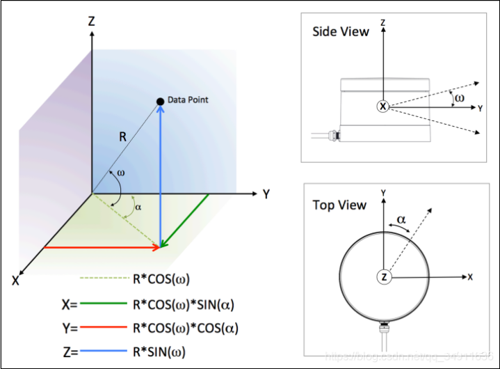
Step 4: Convert angle and distance information to 3D coordinate XYZ values.
3D coordinate XYZ values can be synthesized from the rotation angle α (obtained in Step 1), the vertical angle ω (a fixed value for each laser beam), and the distance value R (obtained in Step 2). The specific coordinate conversion is shown in the following figure.
1.2 Motion distortion compensation
Motion distortion refers to the problem that the position of the point cloud generated by the lidar or its carrier is different within one frame time due to motion.
To understand motion distortion compensation, we first need to know why the lidar point cloud on the autonomous driving vehicle side will produce motion distortion.
In fact, a frame of lidar point cloud emitted by the lidar consists of multiple laser points, and these laser points are formed after one scanning by the scanning device. When the vehicle is in a stationary scene and the target object in the scene is also in a relatively stationary state, the collected point cloud in one frame will not have distortion, and each laser beam will eventually form a closed circle.
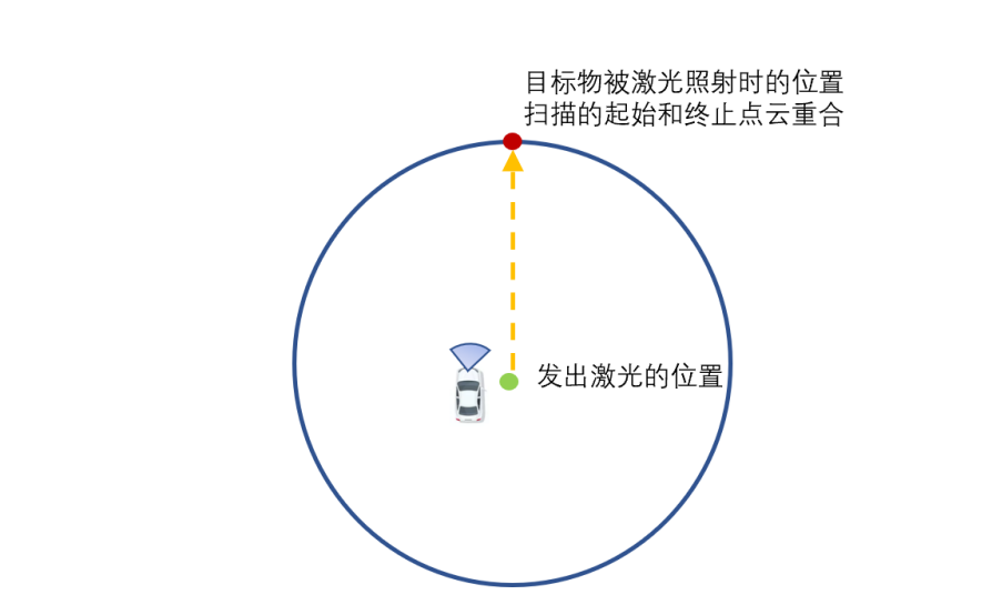
In a moving scene, such as when the vehicle is traveling at high speed or turning, the starting point cloud and the ending point cloud in one frame can only obtain measurement results in different coordinate systems, which results in distortion of the three-dimensional environment information. As shown in the figure below, when the vehicle is in motion, after the lidar on the vehicle completes one full scan, when the last laser beam shines on the target object, compared with the first laser beam shining on the target, the spatial position of the target has undergone a relative displacement – the information displayed on the coordinate system for the object at two different times is different.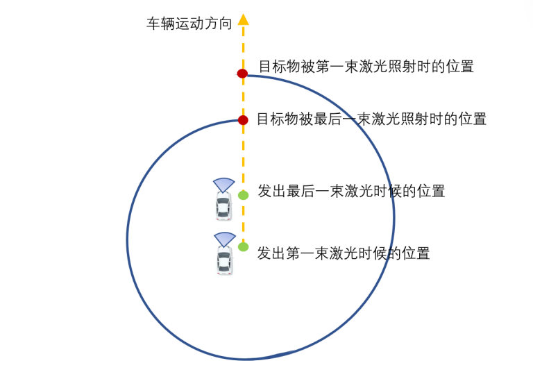
The purpose of motion distortion compensation is to calculate the motion trajectory of the laser during data acquisition and compensate for the changes in motion displacement caused by the motion, thus unifying the point cloud of the same frame into the coordinate system at the same moment.
To further explain motion distortion compensation, an algorithm engineer from a certain host factory gave an example: “For example, if the vehicle is equipped with an IMU or a wheel odometer, the perception algorithm staff can calculate how the vehicle moves within 0.1 seconds using IMU and wheel odometer (or directly with IMU), then use the motion model to compensate for the motion distortion.”
The common methods of motion distortion compensation are:
- Pure estimation methods (ICP/VICP)
The Iterative Closest Point (ICP) method matches two point clouds using the ICP algorithm. After a continuous iteration algorithm, the error between the point clouds is minimized.
The VICP method is a variant of the ICP algorithm, which assumes that the vehicle is moving at a constant speed. At the same time as matching the point cloud, it is used to estimate the vehicle’s own speed.
The Iterative Closest Point (ICP) and VICP are collectively referred to as “pure estimation methods.”
- Sensor-assisted methods (IMU/ODOM)
The Inertial Measurement Unit (IMU) method finds the data of the adjacent two frames in the IMU queue, and then calculates the pose of the laser radar at the scanning point in the same frame using spherical linear interpolation. The coordinate transformation of the two point clouds to the same coordinate system is performed by applying homogeneous coordinate transformation.
The Wheel Odometer (ODOM) method calculates the odometer pose in the coordinate system corresponding to each point cloud in the current frame of laser radar data. The coordinate of each point cloud is transformed twice to the same coordinate system according to the obtained pose, and finally the frame point cloud data is repackaged.
The Inertial Measurement Unit (IMU) and Wheel Odometer (ODOM) are collectively referred to as sensor-assisted methods.
- Fusion Method
This method is a fusion solution that combines odometer and ICP methods. The odometer method is used to correct motion distortion and remove most of it. Then, the ICP method is used for matching and getting the error value of the odometer. The error value is then equally distributed to each point cloud and the position of each point cloud is corrected. Finally, the ICP method is iterated until the error converges.
1.3 Point Cloud Framing
After compensating for motion distortion in the point cloud, perception algorithm personnel will find that the number of point clouds in the data packet sent by the lidar is actually very small, which is completely insufficient for subsequent perception and localization level processing.
At this time, perception algorithm personnel need to process these data packets with point cloud framing.
Regarding point cloud framing, a perception algorithm engineer from a certain L4 solution provider said: “For example, taking a single lidar as an example, perception algorithm personnel will superimpose multiple point cloud data packets on the same frame, so that the point cloud data in this frame can contain tens of thousands of point clouds, in order to facilitate subsequent perception and localization process. If there are multiple lidars on the vehicle, perception algorithm personnel will separately parse the point cloud data packets of these lidars, and then collect the parsed point cloud data at the same time to form a large data packet. For example, technicians will gather the point clouds from multiple lidars on the vehicle at time t together as a frame of point cloud data for processing.”
1.4 Extraneous Variable Changes
The point cloud coordinate system obtained by parsing the point cloud data belongs to the coordinate system of the lidar. In actual application of autonomous driving technology, it is still necessary to convert the coordinate system of the lidar into the coordinate system of the vehicle, which is called extraneous variable changes in point cloud.
Because the lidar is rigidly connected to the vehicle, the relative posture and displacement between the two are fixed and unchanged during the vehicle motion. It is only necessary to establish the positional relationship between the two relative coordinate systems, and by rotation or translation, the two 3D coordinate systems can be aligned to one 3D coordinate system (also called global coordinate system or world coordinate system).
1.5 Filtering Process
In the process of acquiring point cloud data by the lidar, due to the influence of factors such as the product’s own system, the surface of the object being measured, and the scanning environment, the point cloud data will inevitably contain some noise (outliers), which need to be removed directly or processed in a smooth manner. These noise points (outliers) will cause certain errors in the model results in subsequent point cloud processing steps (such as point cloud segmentation, feature extraction, point cloud registration, etc.). Therefore, in the actual point cloud processing process, perception personnel will perform filtering processing on the point cloud.- Noise refers to the point cloud data that is useless for model processing.
- Outliers refers to the point cloud data that is far away from the main observation area.
In the interview with experts, the author learned that in the autonomous driving industry, noise generally includes outliers. Therefore, in subsequent articles, the author will use noise as a general term.
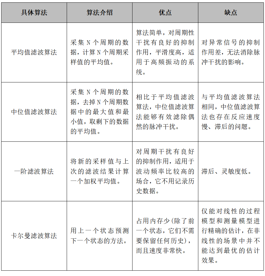
The following table lists commonly used filtering algorithms in the autonomous driving industry.
Table: Common Filtering Algorithms in the Autonomous Driving Industry
Perception processing
After the entire point cloud preprocessing is completed, perception algorithm personnel will carry out perception and positioning processing on the point cloud data respectively.
In the perception processing flow, point cloud data is mainly used for 3D object detection, that is, the autonomous driving system needs to recognize and detect obstacles in the vehicle perception area, and take avoidance measures.
After the point cloud preprocessing is completed, there will be two branches in the perception processing: one is to apply traditional 3D object detection methods, including point cloud segmentation and clustering analysis of target objects; the other is to directly apply deep learning models to complete 3D object detection.
The following sections will respectively analyze the point cloud 3D object detection process based on two different methods.
2.1 Perception data processing based on traditional methods
(1) Ground point cloud segmentation
After object detection, a large part of the point cloud data belongs to the ground point cloud data and presents a certain texture, which will affect the subsequent point cloud processing flow of target objects.
On the one hand, if these ground point cloud data are not segmented and removed, these invalid point cloud data will interfere with the target object point cloud data on the ground, and reduce the accuracy and robustness of the target obstacle segmentation algorithm. On the other hand, due to the large amount of point cloud data, this will increase the model’s demand for computing power.
Therefore, before proceeding to subsequent work, perception algorithm personnel need to filter the ground point cloud.
Since the convolutional neural network model generally extracts features from each local area in a sliding window manner and then performs classification and regression, deep learning methods often do not need to pre-segment the ground point cloud. In the field of autonomous driving, considering the factors such as hardware performance consumption, development cycle, and model maturity, perception algorithm personnel generally use traditional algorithms for ground point cloud segmentation.
The author has summarized several common ground point segmentation methods:
- Planar Grid Segmentation
Main idea: Planar Grid Segmentation usually establishes planar grids (or multiple layers of grids or 3D voxels) based on the set dimensions. Then, the original point cloud is projected into each grid, and features such as average height, maximum height, height difference, density, etc., are extracted for each point cloud set in the grid.
Technical highlights: Without considering vector features, subsequent planning and control can be more easily implemented.
Problems: When the laser beam is relatively scarce, for example, when a 16-line laser radar is collecting road data, the laser points that can reach the ground 20 meters away in front of the vehicle are already relatively scarce, and usually only one laser beam can hit the obstacle. If height features are used for ground filtering in the grid, Low and short obstacles are easily filtered out as ground points.
- Point Cloud Normals
Main idea: Point Cloud Normals refer to using the angle threshold set for the point cloud to segment the ground point cloud. Normally, the normal vector for ground point clouds is vertical. Only the angle between the normal vector and the ground vector of the point cloud needs to be solved by the model, and the threshold set can be used for comparison and classification. This method requires the support of neighboring points, and the size of the neighborhood is generally represented by the neighborhood radius value or the number of adjacent points. An overly large neighborhood can level out the three-dimensional structural details, making the normal vector unnecessarily rough, while an overly small neighborhood with too few points will be strongly affected by noise.
Technical highlights: This method can well extract the point cloud set where the normal vector of the road suddenly changes, forming a road edge, and then cooperate with rasterization to partition the road area, non-road area, and obstacles.
Problems:
1) According to the assumption of the normal vector method, point cloud correction must be performed first. If not, an extreme case may occur where no ground points are segmented in a certain frame (when the tilt angle of the laser radar is too large).
2) The normal vector method cannot effectively distinguish the points generated by platform-type obstacles (such as rectangular flower beds on the roadside).
- Model Fitting – Plane Fitting (RANSAC)
Main idea: RANSAC Plane Fitting refers to using three randomly selected point clouds to establish a plane equation, and then sequentially inputting point cloud data into the plane equation. Then, the point is judged whether it is a point in the plane according to the set distance threshold. For example, points within the threshold range are regarded as internal points, and points outside the threshold range are regarded as external points. The plane equation with the most iterations is the ground equation, and the internal points in the equation are a set of ground points, and vice versa for obstacle point clouds.## Technical Highlights
This method can accurately estimate model parameters even when there are a large number of outlier data in the dataset, making it easier to estimate ground point clouds from large-scale point cloud data.
Issues
1) Considering the drainage factors, the traffic road is usually convex in the middle and concave on both sides, similar to the shape of an arch bridge. Although the curvature is not large, the planar equation inclined to one side may be obtained as the ground equation by calculating the ground plane using the random sampling consensus algorithm.
2) When going up or down a slope, due to the non-planarity of the ground, the ground equation calculated by this method will result in the situation that the points of front ground are taken as obstacle points.
3) Since RANSAC randomly selects three points to construct a plane in point cloud space, if there are large wall surfaces in the scene, the situation of the wall surface being taken as the ground equation may occur.
- Mesh Surface Method
Main Idea: The segmentation of mesh surface can be divided into local type or surface type, and the ground segmentation is usually performed by using the region growing method. The main idea is to compare the angles between the point normals based on the mesh surface and merge adjacent points that satisfy the smooth constraint into a cluster, which is considered as belonging to the same plane.
Technical Highlights
This method can handle the curvature of the ground well, and achieve good segmentation results for relatively smooth curved or flat surfaces.
Issues
1) There are too many noisy points in the actual road. Directly segmenting the ground using the region growing method will result in many scattered ground points being considered as obstacle point cloud.
2) The computational time of the region growing algorithm is relatively long. For perception algorithm modules that require real-time performance, further optimization is needed, such as reducing the region growing to the edge of the plane, or dividing the region for segmentation in a small range, etc.
2. Segmentation of Point Clouds of Target Objects
After removing the ground point cloud, perception algorithm staff need to effectively segment and block the point clouds of target objects, so as to facilitate separate processing of target objects, namely point cloud segmentation. The segmentation of target obstacle point clouds is divided based on spatial, geometric, and textural features, etc.
Here are several commonly used methods for point cloud segmentation:
- Edge-based Method
Main Idea: Edge-based method describes the shape of an object particularly by its edge, so it searches for points near the edge of target objects through locating the rapidly changing points in point clouds, and segments the points in the vicinity of target objects.
Technical Highlights
The method utilizes a reconfigurable multiring network algorithm optimization mechanism, which improves the efficiency of the algorithm.
Existing Issues:
-
The method is best suited for simple scenarios (such as low noise and uniform density) and is not suitable for datasets with a large number of 3D point clouds.
-
Faced with target point cloud data with discontinuous edges, if point cloud fill is not used, it cannot be directly used for recognition and detection.
Region-growing-based Methods
Main Idea
Region-growing-based methods classify nearby points with similar attributes using neighborhood information to obtain segmented regions, and differentiate the differences between different regions based on the classified regions. This method is mainly divided into two categories: seed region method and non-seed region method. The seed region method is used to start segmentation by selecting multiple seed points. These seed points are used as the starting point, and the point cloud region is gradually formed by adding the neighborhood points of the seed. The non-seed region method divides all points into one region and then subdivides it into smaller regions.
Technical Highlights:
Comparing to the edge-based methods, this method has higher segmentation accuracy.
Existing Issues:
This method depends on the selected initial seed points, or the position of the region subdivision. If inappropriate selections are made, it can cause issues such as over-segmentation or insufficient segmentation.
Attribute-based Methods
Main Idea
The attribute-based method first calculates the attributes of the target point cloud, such as the distance, density, and the horizontal or vertical distribution of the point cloud, and uses this to define the neighborhood between measuring points. Then, the slope of normal vectors and difference in the data of point neighborhood in each direction are used as the clustering attributes.
Technical Highlights:
Compared to the previous two methods, attribute-based methods can eliminate the influence of outliers and noise.
Existing Issues:
This method depends on the point-to-point neighborhood definition and the point cloud density of the point cloud data. When dealing with multi-dimensional attributes of a large number of input points, it can lead to the model requiring an excessive amount of calculation power.
(3) Clustering Analysis of Targets
After the point cloud segmentation of the target point cloud is completed, the perception algorithm staff needs to cluster the segmented point clouds into several aggregates, that is, group similar point clouds into one group to reduce the computational complexity of subsequent models. This process is called point cloud clustering.
The common point cloud clustering methods are as follows:
K-Means
Main Idea
K-means clustering algorithm refers to dividing the entire point cloud dataset into k point clouds clusters with a unified feature. First, select k points at random as the center of each point cloud cluster. Then, calculate the actual distance between each point cloud cluster and the k points above, and cluster them to the point cloud cluster with the minimum distance. Then, calculate the centroid coordinates of the clustering point clouds, and update the center point of the point cloud cluster. Finally, the model repeats the above steps until the center point of the point cloud cluster no longer changes.
Technical Highlights
- High accuracy
- Capable of handling large amount of data
- Fast computation speed
DBSCAN
Main Idea: DBSCAN introduces the concept of density, requiring that the number of objects in a certain area in the clustering space should be no less than a given threshold. This method can detect clusters of any shape in a spatial database with noise and connect adjacent regions with sufficiently high density. It effectively deals with outliers and is mainly used for clustering spatial data.
Technical Highlights:
1) Can cluster point clouds of any shape
2) Can effectively remove noisy points
Existing Issues:
1) Consumes a lot of memory resources
2) High requirement for processors
3) The radius and triggering threshold of the clustering area need to be pre-set
Euclidean-based Clustering
Main Idea: Euclidean-based clustering (also known as Euclidean distance clustering) is a method based on clustering with the Euclidean distance. In the point cloud data of LiDAR, when the distance between two points in the cluster of the same object is less than a certain value, and the distance between the point cloud clusters of different objects is greater than a certain value, the Euclidean clustering algorithm merges the points that have a Euclidean distance less than the set distance threshold into one category, thus completing the clustering process.
Technical Highlights:
1) Fast computation speed
2) Good generality
Existing Issues:
The algorithm requires a fixed distance threshold to be preset, which may lead to better clustering effect for nearby objects but worse for distant objects.
Matching and Tracking
After completing the previous sections, perception algorithm personnel can already know what specific targets these point clouds represent from the processed data. The next step is to match and track the target objects, i.e., predict where the target object will appear in the next moment. In obstacle detection, the accuracy of matching is the foundation of subsequent multi-sensor fusion.
Usually, the algorithm flow of matching and tracking is to first calculate the correlation matrix between the predicted result of the target and the measured point cloud data. Then, using the Hungarian algorithm (whose core principle is to find an augmented path to achieve maximum matching), the matching relation is determined. Finally, the point cloud data is divided into matched and unmatched targets for storage and tracking preparation.### 2.2 Perception Data Processing Based on Deep Learning
In the field of autonomous driving, traditional object detection algorithms can no longer meet practical needs as the amount of point cloud data increases. According to conversations with various experts, the current 3D object detection of point cloud mainly adopts deep learning models.
A perception algorithm engineer from a certain automaker said: “In the object detection at perception level, after preprocessing the point cloud, it is directly input into the deep learning model, or down-sampled before inputting into the deep learning model.”
Frequently used deep learning-based object detection methods:
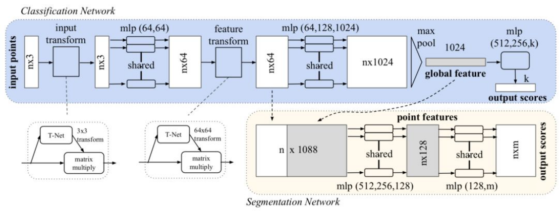
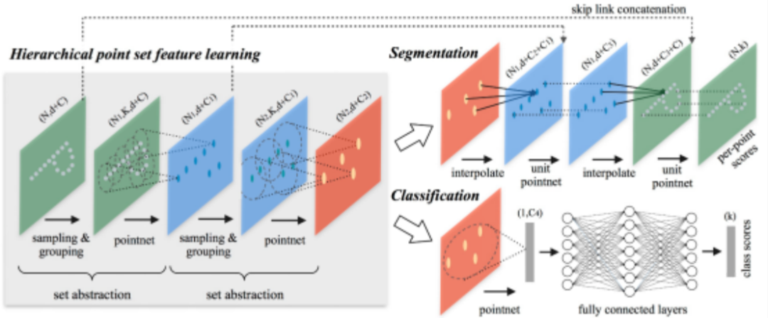
- PointNet
Main idea: Firstly, PointNet calculates the features of each point in the point cloud, and then combines these features with an operation that is independent of the point cloud sequence, obtaining features belonging to the entire point cloud. This feature can be directly used for task recognition.
Technological highlights:
1) Inputting point cloud data directly into the network without normalization;
2) Utilization of rotation invariance and permutation invariance.
√Rotation invariance: Same transformations (rotation, translation) on all points do not affect the expression of the shape.
√Permutation invariance: Any permutation of the position of each point does not affect the expression of the shape.
Issues: Unable to obtain local features, which makes it difficult for PointNet to analyze complex scenes.
- PointNet++
Main idea: PointNet++ is derived based on the PointNet method, mainly borrowing the idea of multi-level receptive field from CNN. By continuously using convolution kernels to scan pixels on the image and performing inner products in layers, CNN makes the feature maps at the back have larger receptive fields and more information contained for each pixel. PointNet++ implements this kind of structure by firstly sampling the entire point cloud locally and dividing it into several regions, and then taking the points inside the regions as the local features to perform feature extraction using PointNet.
Technical Highlights
1) No information loss caused by quantization and no need to adjust quantization hyperparameters.
2) Ignore blank areas, avoiding invalid calculations.
- VoxelNet
Main idea: VoxelNet mainly converts three-dimensional point clouds into voxel structures, and then processes this structure in the form of a bird’s-eye view. The voxel structure here uses the same size cubes to divide the three-dimensional space, each of which is called a voxel.
VoxelNet has two main processes. The first one is called VFE (Voxel Feature Extraction), which is the voxel feature extraction process. The second one is similar to the object detection process of YOLO.
Technical Highlights
1) Tasks detection can be directly performed on sparse point cloud data, avoiding the information bottleneck caused by manual feature engineering.
2) GPU’s parallel computing advantage can be utilized more effectively.
Problems
VoxelNet is relatively inefficient in terms of data representation (a new data structure reconstructed to adapt to the model operation), and the demand for computing power of the 3D convolution in the middle layer is too high, resulting in a running speed of only about 2FPS (Frame Per Second), which is far lower than the real-time requirement.
Existing Problems
1) Unable to utilize mature spatial convolution-based 2D object detection algorithms.
2) Although invalid calculations are avoided, GPU processing efficiency for point clouds is much lower than that for mesh data.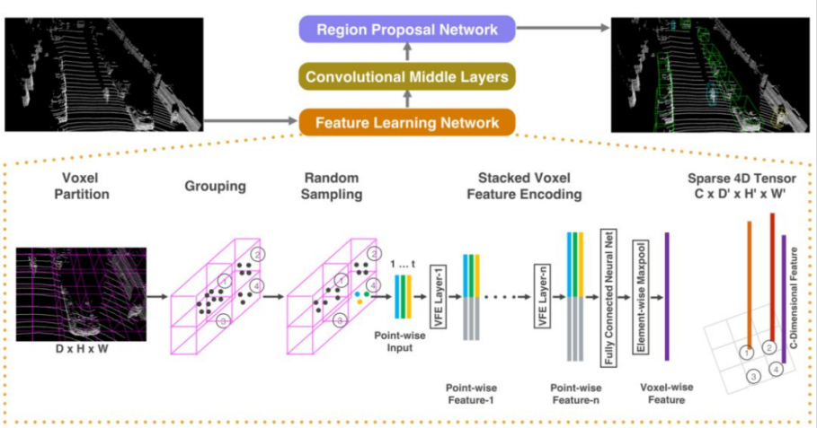
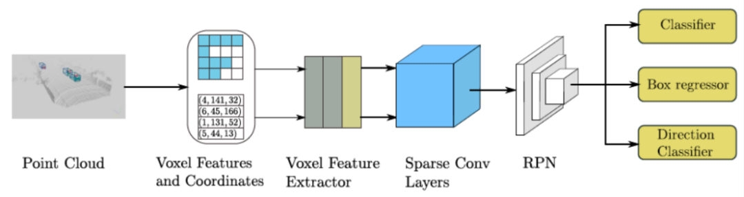
- SECOND
Main Idea: SECOND is an optimized point cloud detection method based on the VoxelNet method, and its overall network structure and implementation are mostly similar to the original VoxelNet. At the same time, the 3D convolutional layer in the middle layer of VoxelNet has been improved by using sparse convolution. This method improves the efficiency of training and the speed of network inference. Meanwhile, SECOND proposes a new loss function and point cloud data augmentation strategy. The structural design of SECOND consists of three parts: VFE feature extraction stage, sparse convolutional layer, and RPN network.
Technical Highlights: The use of sparse convolution improves the speed of the model’s inference.
Existing Problems: Although SECOND’s speed has been improved compared to VoxelNet, it still retains 3D convolution.
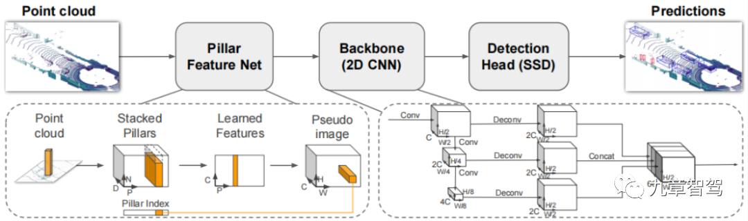
- PointPillars
Main Idea: PointPillar stacks the points that fall into each grid together, and then learns features in a similar way to PointNet. Finally, the learned feature vectors are mapped back to the grid coordinates to obtain data similar to images.
Technical Highlights:
1) By learning features instead of relying on fixed encoders, PointPillars can use all the information represented by the point cloud.
2) By operating on pillars instead of voxels, there is no need to manually adjust the vertical direction of packing.3) Only 2D convolutions are used in the network, without 3D convolutions, which requires less computation and is highly efficient in operation.
4) Different point cloud configurations can be used without manual adjustment.
Existing issue: Learning point features is restricted to the grid and cannot effectively extract information from neighboring regions.
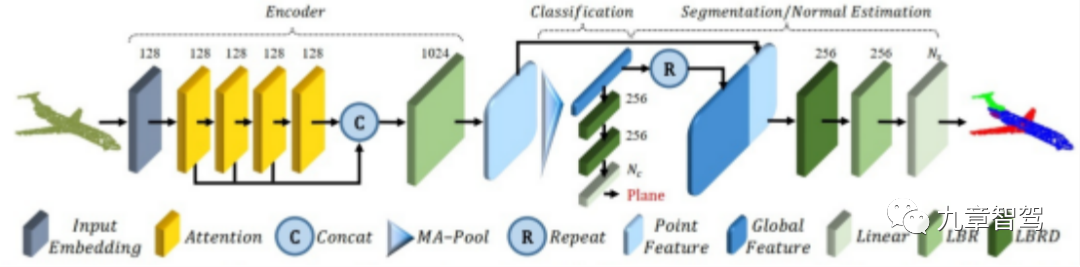
- PCT
Main idea: PCT mainly utilizes the inherent permutation invariance of Transformers to avoid defining the order of point cloud data, and uses attention mechanisms for feature learning. The network structure is divided into three parts: input embedding, attention layer, and point cloud classification and segmentation.
Technological highlights:
1) PCT has inherent permutation invariance, making it more suitable for point cloud learning.
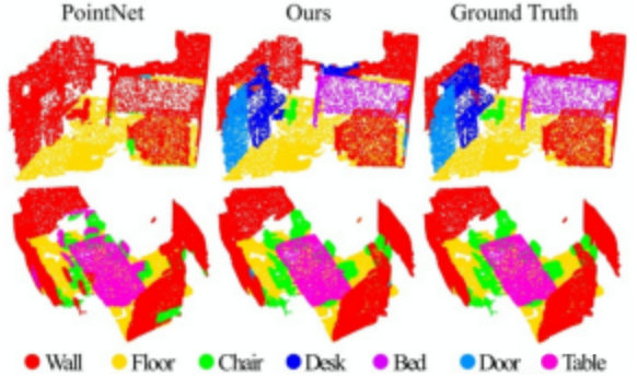
2) Compared with the mainstream PointNet network, PCT has clearer segmentation edges.
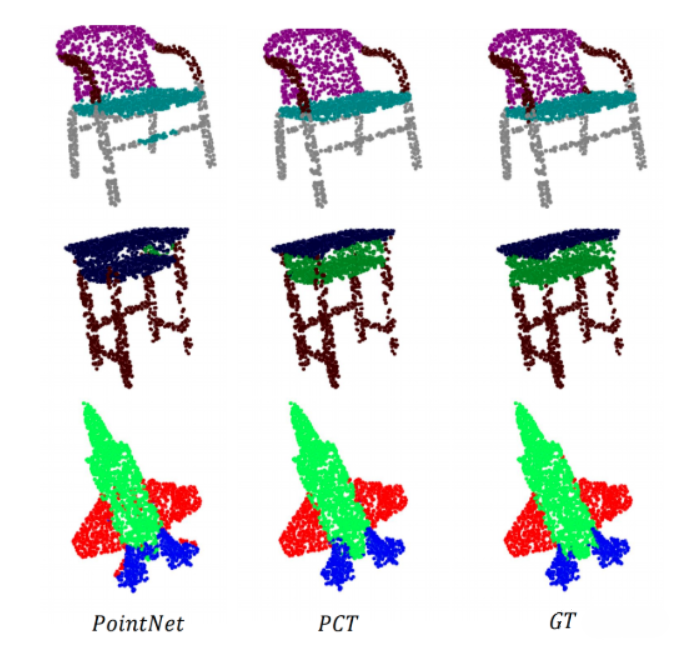
Existing issue: PCT is an effective global feature extraction network, but it ignores the equally important local neighborhood information in point cloud deep learning.
Although deep learning has been widely used in the field of autonomous driving, it also faces some challenges in point cloud data processing.
On the one hand, as the position of points in point clouds are sparse and unstructured, their density and quantity vary with changes in objects in the scene. On the other hand, because automatic driving vehicles need to respond very quickly, object detection must be performed in real-time, which means that the detection network must provide computing results within the time interval between two scans.Therefore, although deep learning is available and useful, it cannot be fully used.
Xu Jian said, “The current AI algorithms, including deep learning, cannot achieve 100% accurate recognition and detection, which can easily lead to target omission. AI algorithms are a very important means of 3D point cloud perception, but cannot rely solely on AI. By comprehensively applying AI algorithms and traditional algorithms, we can solve the problem of incomplete data sample space and avoid target omission.”
Handling at the Function Layer
3.1 Feature Extraction
When autonomous driving vehicles are on the road, they do not know where they are, so the first step in using point cloud data for positioning is to let the autonomous driving vehicle know “where am I.”
At this time, the perception algorithm staff needs to first extract the target object features of the surrounding scene, and establish a small map through these features and the obtained relative distance information to know the relative initial position of the vehicle.
Point cloud feature extraction is often real-time, which will cause the data volume of point cloud to be very large, and the hardware performance of existing mass-production vehicles is limited. Therefore, in order to reduce the calculation of point cloud data, some more obvious features, such as the contour information of the object, are usually extracted first when point cloud data is extracted.
An algorithm engineer of a certain automaker said, “Lidar will not have semantic information with depth like vision. In order to reduce the calculation amount, Lidar will only extract the features of the target object, mainly the ‘line-face-angle’ features of the target object. For example, the electric pole is the feature of the line, the road surface is the feature of the plane, and the angular points of the building are the feature of the angle.”
3.2 Map Matching
After extracting the features of the surrounding target objects, the perception algorithm staff needs to perform point cloud map matching based on these features to obtain the relative positions between the point clouds. Point cloud map matching can generally be divided into inter-frame matching and high-precision map matching.
-
Inter-frame matching, also known as subgraph matching, refers to matching the point clouds with the same features in the front and rear frames, and finally obtaining a local small map.
-
High-precision map-matching refers to matching the optimized point cloud with a high-precision map.
In the autonomous driving industry, autonomous driving solutions vendors or automakers will use these two different approaches, but the frequently used matching method is mainly based on inter-frame matching.
An algorithm engineer of a certain automaker said, “Perhaps only the level-4 unmanned driving project is based on high-precision map positioning solution for map matching, while automakers mainly adopt inter-frame matching, because the positioning solution of mass-produced vehicles cannot all be based on high-precision maps. In addition, the calculation amount of high-precision map matching is very large, and downsampling work must be done before application.”### 3.3 Pose Optimization
As mentioned earlier, after the point cloud data is matched, the relative poses between the point clouds can be obtained, and the accuracy of the relative poses affects the accuracy of map construction. Therefore, it is necessary to optimize the relative poses of the point cloud.
Generally speaking, the inaccuracy of the relative poses is mainly caused by uncontrollable factors, such as occlusion of point clouds by objects or limitations of the laser radar field of view. Pose optimization of point clouds obtains the optimal relative poses through rigid transformations (rotation or translation) of a certain point cloud coordinate system.
References
[1] What do you know about LiDAR point cloud data?
https://blog.csdn.net/OpenDataLab/article/details/124962277
[2] Learning Notes: Introduction to Point Cloud Library (PCL)
https://blog.csdn.net/jeffliu123/article/details/126137566
[3] Introduction to Point Cloud Concepts and Point Cloud Processing
https://blog.csdn.net/hongju_tang/article/details/85008888
[4] A Summary of Basic Performance Indicators of LiDAR
http://www.360doc.com/content/20/0813/07/71135856_965448273.shtml
[5] Preprocessing of LiDAR Point Clouds
https://zhuanlan.zhihu.com/p/455810371
[6] Motion Compensation Method for LiDAR
https://zhuanlan.zhihu.com/p/470795318
[7] Calibration of LiDAR
https://blog.csdn.net/qq39032096/category11512741.html
[8] Overview of Object Detection Based on 3D Point Clouds
https://zhuanlan.zhihu.com/p/479539638
[9] LiDAR Object Detection in Autonomous Driving (Part Two)
https://mp.weixin.qq.com/s/3H6qCDO-2mOP3HjGKnmLzw## [10] A Survey of 3D Point Cloud Segmentation (Chinese)
https://mp.weixin.qq.com/s?_biz=MzI0MDYxMDk0Ng%3D%3D&chksm=e9196bc2de6ee2d4220fbf4fca46ea676eadac19a4e17b5b3d4dd9c0aa772c0b57db57f5a044&idx=1&mid=2247487535&scene=21&sn=1c6687b0a7c6df60dc0bd902676c0ed0#wechatredirect
[11] Research Progress on Point Cloud Clustering Algorithm for Autonomous Driving Vehicles (Chinese)
https://mp.weixin.qq.com/s?__biz=MzI0MjcxNDQwNQ==&mid=2247488019&idx=1&sn=be3089b2510cfb12b2a955990f9c7e3b&chksm=e9794059de0ec94fb9559cfd011c173424586de115a943376c094e6572af5dcf74121239a009&scene=27
[12] Obstacle Detection and Tracking Based on 3D LiDAR (Chinese)
https://mp.weixin.qq.com/s/ULDIkGSUfVp3OwWgxR2A9g
[13] Autonomous Driving – Filtering Algorithm (Chinese)
https://blog.csdn.net/limeigui/article/details/127656052
This article is a translation by ChatGPT of a Chinese report from 42HOW. If you have any questions about it, please email bd@42how.com.