
Author | Dou Mingjia
What is Vehicle Mode Management VMM
Vehicle Mode Management (VMM) is simply to divide the vehicle into different modes based on the different states during the entire lifecycle of the vehicle and the different scenarios of the user’s use of the vehicle, including Car Mode and Usage Mode.
1.1 Car Mode
This mode includes the entire process from the birth to scrapping of the vehicle, including Factory Mode, Transport Mode, Normal Mode, Crash Mode, and Dyno Mode:
a) Factory Mode
Mainly to deal with the needs from the vehicle manufacturing process, such as limiting functions that may cause internal components to scratch or dirty the vehicle. For example, entertainment and air conditioning functions are not required to be turned on during the vehicle manufacturing process, so the VMM Function Matrix can define that the entertainment and air conditioning functions cannot be turned on in Factory Mode. At the same time, IVI and air conditioning software should also follow such requirements during development. In addition, if it is necessary to test or drive the vehicle during the Factory Mode, it is possible to temporarily enter the Normal Mode by specific operations (such as pressing the hazard alarm switch twice), suspend the Factory Mode, and switch the Car Mode from Factory Mode to Normal Mode. After the vehicle is turned off, switch back to Factory Mode.
b) Transport Mode
Similar to Factory Mode, according to the vehicle transportation scenario, some functions are disabled to avoid accidentally scratching the vehicle and low battery power consumption, which may cause the vehicle to be unable to start, especially in the scenario of long-distance sea transportation. Such disabled functions may include disabling the welcome function, Bluetooth key, remote control function (T-BOX enters deep sleep state), and prohibiting the suspension adjustment function to be turned on.## Car Mode Status Switching Example
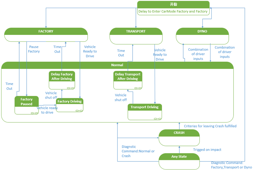
c) Dyno Mode
This is a unique mode that allows the test vehicle to run correctly and safely on a dynamometer. When the vehicle is tested on a dynamometer, automatic braking and steering may cause dangerous situations. Therefore, the vehicle can be safely operated by writing diagnostic information into this mode.
d) Normal Mode
The vehicle is in Normal Mode when delivered to the customer, and Car Mode should remain in this mode throughout the vehicle’s normal lifecycle, unless a collision occurs. When in Normal Mode, the availability of vehicle functions is primarily based on Usage Mode (described below). The vehicle may briefly enter Normal Mode during factory and transport modes.
e) Crash Mode
When the vehicle detects a collision, it broadcasts the collision event and disables certain functions to enhance vehicle safety; the vehicle is in a limp-home state and normal function cannot be guaranteed.
1.2 Usage Mode
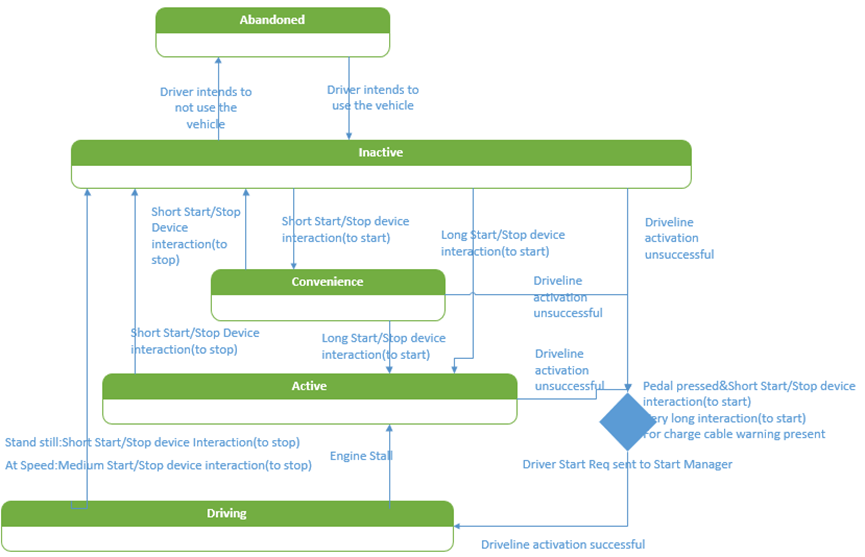
The primary purpose of Usage Mode is to provide consistent behavior in terms of the availability of vehicle functions. VMM-Usage Mode can detect user intent through user operations and provide corresponding levels of function access:
a) Abandoned Mode
This mode is entered when the vehicle is parked and enters sleep mode, and only a few functions are available, such as alarm, remote control, and remote information processing. The vehicle switches from Abandoned Mode to Inactive Mode when the driver (approach detection), remote requests (OTA), or remote control functions (e.g. remote unlocking, remote air conditioning, etc.) will be used.
b) Inactive Mode
Typical scenarios where the vehicle can be in Usage Mode-Inactive Mode include:- The driver enters the vehicle (unlocking the vehicle, opening the door, etc.);
- Remote air conditioning/remote start/remote monitoring, etc.;
- Vehicle charging;
- After parking, the user presses the SSB one-button start switch, and the Usage Mode will directly switch to Inactive Mode;
If the vehicle remains in Inactive Mode for a period of time (usually set to 15 minutes), the Usage Mode will switch from Inactive to Abandoned Mode. Therefore, even if the user forgets to lock the car, the vehicle will enter a hibernation state, ensuring the minimum static power consumption of the vehicle, and preventing the problem of the user’s inability to start the vehicle due to battery discharge;
c) Convenience Mode
This mode can only be switched from Inactive Mode. For example, when the user presses the one-button start switch when the vehicle is turned off, the vehicle can switch from Usage Mode-Inactive Mode to Usage Mode-Convenience Mode. In this mode, typical functions that can be activated include electric windows, electric seats, rain wipers, wireless charging for mobile phones, and playing music, ensuring the user’s use of the vehicle in a stationary state.
d) Active Mode
This mode is mostly used in trailer scenarios and should not be viewed as a normal user mode. Most functions are available in this mode (except for the drive system), so the power consumption of the entire vehicle is relatively high. This mode also requires conscious operation by the user to enter (such as long-pressing the one-button start switch).
e) Driving Mode
When the user’s intent to start the vehicle is detected (such as the user stepping on the brake pedal and pressing the one-button start switch), the vehicle enters this mode, which will activate the necessary power control logic (such as closing the IG1 relay and the start relay, disconnecting the ACC and IG2 relays, and then disconnecting the start relay after the vehicle is started, closing the power relay (ACC relay, IG1 relay, IG2 relay), etc.
 ## Why Vehicle Mode Management VMM Is Required
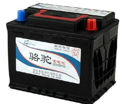
Whether it is a gasoline-powered car or the current pure electric, hybrid, and hydrogen fuel cell vehicles, they all need to be equipped with a low-voltage battery (12V or 24V). The main functions of this low-voltage battery are as follows:
- Provide power for the static current consumption of the vehicle during sleep mode;
- Supplement energy when the overall electrical load of the vehicle exceeds the output current of the generator (gasoline-powered cars) or DC-DC converter (new energy vehicles) during driving;
- Provide power for cold start of the vehicle;
- Absorb voltage fluctuations (such as load dump conditions) during vehicle operation as an energy storage device.
When the vehicle is in production, transportation, storage or non-starting state for customer use, the entire vehicle’s electric energy comes from this small low-voltage battery. Especially in current new energy vehicle models, considering space, cost, weight, and the ability to start an engine, the capacity of this battery is getting smaller and smaller. Therefore, VMM is used to manage the availability of vehicle functions and provide appropriate functions at the appropriate time, while reducing the consumption of electrical energy, so as to ensure that the low-voltage battery has enough power to start the vehicle. Meanwhile, the reduction in energy consumption leads to a reduction in emissions (such as CO2) and the cost of vehicle use (1 watt ≈ approximately 6 RMB).
What is the Relationship between Vehicle Mode Management VMM and Power Mode
3.1 Power Mode
KL15, KL30, KL31, KL50, and KLR are the power modes we are familiar with. Most OEMs assign the corresponding mode power according to the power mode needs of the electrical appliances during the overall vehicle power distribution design.
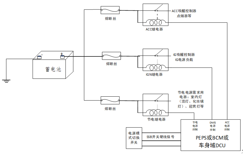
- KL30 (BAT+): Constant power supply directly connected to the battery positive pole. Usually used for ECUs with wake-up requirements (such as PEPS, BCM, DCM, T-BOX, etc.), ECUs with after-run needs (such as ESC), and ECUs with permanent storage needs.- KL15 (IGN): ON power mode, which is usually connected to the IGN relay and controlled by the EEPM (Electrical Energy and Power Management) module. Electrical loads related to vehicle startup and operation, such as ECM and TCU, are usually connected to this power mode;
- KL31 (GND): Battery negative pole. Currently, most low-voltage power grids in vehicles on the market use a single-wire system, where the battery negative pole and the negative pole of the electrical loads are directly connected to the same potential of the vehicle body;
- KL50 (Crank): Engine ignition status;
- KLR (ACC): This power mode is usually connected to the ACC relay, and some comfort and entertainment loads are connected below, such as seat control, window control, and multimedia control.
Note: The above division of power modes is based on the situation of most vehicle models on the market, but this does not mean that there are only these power modes in the entire vehicle power distribution network. For example, a certain French brand may have the following power modes: +BAT, +BAT_CSP/Shunt park, +CPC, +CAN, +APC, +ACC.
3.2 Relationship between VMM and Power Mode
The control of the above power relays (power-saving relay, ACC relay, IG1 relay, IG2 relay) does not completely depend on the Usage Mode of the vehicle, but the Usage Mode has an important influence on the Power Mode, for example:
- When Usage Mode=Inactive, the power-saving relay is usually closed, and the overhead lamp, reading lamp, foot lamp, door lamp, and glove box lamp can be turned on;
- When Usage Mode=Convenience, the ACC relay and power-saving relay are usually closed, and the comfort and entertainment loads inside the vehicle can operate;
- When Usage Mode=Active, the power-saving relay, ACC relay, and IG1 relay are usually closed.- When Usage Mode is set to Driving, all power mode relays are in a closed state.
However, besides the impact of Usage Mode on the power mode relays as mentioned above, the power mode relays can also be controlled independently of the vehicle usage mode, for instance, when the user cancels the power-saving delay function through the central control screen while in Inactive mode, the power-saving relay may remain open.
Intelligent Power Distribution Design Based on VMM
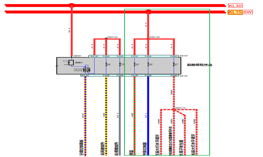
4.1 Drawbacks of Traditional Power Mode-Based Power Distribution Design
As shown in 3.1, the power mode Power Mode design based on the vehicle mode VMM has finite power modes that can be classified into. Therefore, when designing the whole vehicle power allocation network, multiple electrical appliances may share one relay for power control, which is not necessary for some users in certain scenarios. The controller corresponding to this function remains in Active mode, which leads to high power consumption in the whole vehicle low-voltage system after accumulated usage. For instance, when the vehicle is in the driving condition and the power mode is set to IGN, the user does not need to use the air conditioner, while the control of the heat pump controller remains active and consumes significant power. If all controllers remain in Active mode without usage needs, the accumulated power consumption of the whole vehicle’s low-voltage system will directly affect the final fuel consumption and driving range of the vehicle.
4.2 Intelligent Power Distribution Based on Vehicle Mode VMM
In the current area architecture, the area controller ZCU replaces the traditional central electrical box, using distributed area intelligent power distribution. Traditional fuses and relays are replaced by eFuses, HSD, MOSFET, etc., not only achieving advantages such as fault diagnosis, fault protection, and self-recovery for short circuits, open circuits, overcurrent, overvoltage, etc. but also providing more flexible power supply control based on user usage mode (Power-on or Power-down Power supply channel based on use case definition) because each electrical appliance is controlled by an independent power chip.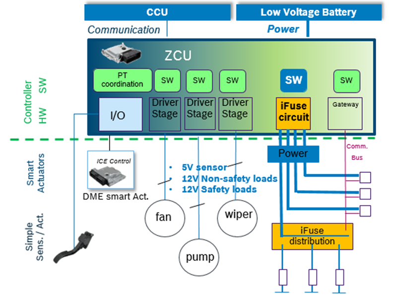

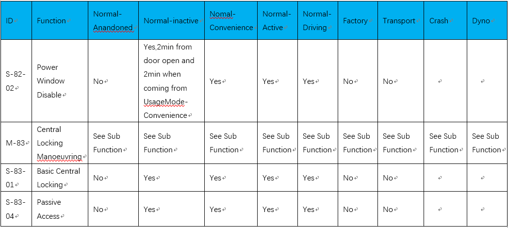
4.2.1 Preparation of VMM Matrix
The main function of VMM Matrix is to determine the available state of functions in different vehicle modes, and to constrain whether a function can be enabled in certain vehicle mode or whether a function needs to be disabled when switching vehicle modes, etc.
4.2.2 Query Device ID According to Function
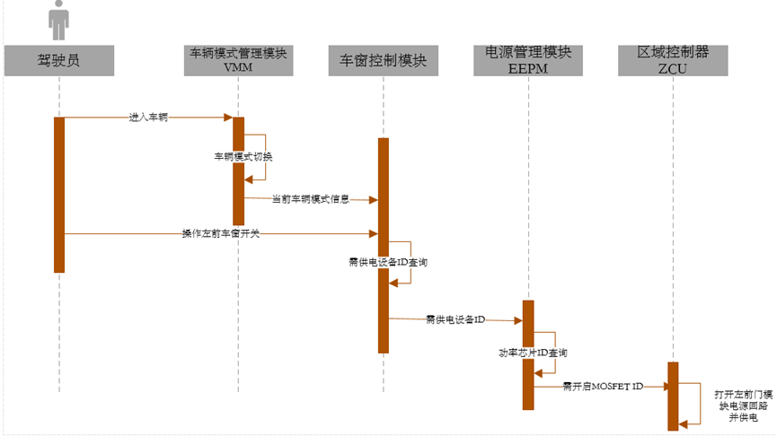
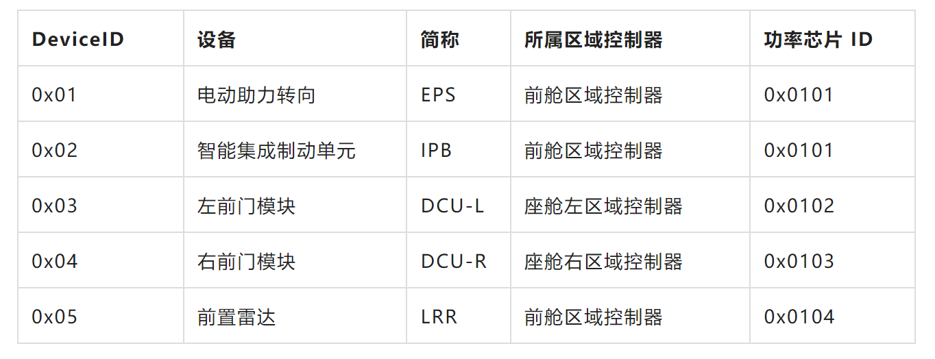
According to the mapping of vehicle mode and function in VMM Matrix, various application software modules located in the central computing unit CCU need to receive the current vehicle mode information – VehicleModeSts. They need to judge whether functions can be enabled in this mode and receive all input conditions. When it is determined that the function can be enabled, they need to query the hardware devices required for their own function implementation, and tell the corresponding device ID to the power management module EEPM. The power management module EEPM queries the mapping table of devices and power chips (such as Table 2), and inputs the MOSFET ID corresponding to the required device to the area controller ZCU via Ethernet, and the area controller ZCU opens the corresponding MOSFET to supply power to the device. For example, the vehicle mode management module VMM, the window control module WCM, and the power management module EEPM are all application-level software located in CCU.
 ## Left front window control power supply timing diagram
With the above technical solution, the power supply of each device can be independently controlled according to the vehicle mode of use, and the power supply of the device corresponding to the function requirement can be turned on in the case of functional demand, thereby avoiding the devices being in Active mode or Standby mode for a long time without any demand, thus reducing energy consumption.
Conclusion
The above introduces a method of power control under the area architecture. The electronic fuse wire is used instead of the traditional insurance and relay. The power distribution is more flexible and fine-grained based on user’s functional requirements. However, there are still many problems that need to be overcome in the process, such as:
-
The area controller takes on intelligent power distribution. The cost of using eFuse is relatively higher than that of the early traditional fuse relay, especially for high-power chip of output current greater than 30A.
-
At present, the power interface design of the Sensor&Actuator ECU under the area controller is still the traditional Bat+IGN mode. The wake-up of the ECU still requires the power status IGN. If it is powered by Efuse under the area controller, BAT and IG need to be connected to the Efuse output pin together, and the wire design is a problem.
-
All vehicle functions must obey the commands of VMM, and OEM needs to have strong control over the function development of various suppliers.
Area architecture intelligent power distribution has just emerged, and there are certainly problems, but they are not insurmountable and require the joint efforts of colleagues.
References:
-
Public Account: New Energy Vehicle Electronic and Electrical Architecture – “Vehicle Mode Management Development”
-
Toshiba Semiconductor eFuse IC.
This article is a translation by ChatGPT of a Chinese report from 42HOW. If you have any questions about it, please email bd@42how.com.