BOOT Origin
Have you ever encountered the scenario where the computer prompts you to reboot after installing new software? Reboot, as we all know, means to restart, and Boot means to start up. But have you ever wondered why computer startup is called Boot? Isn’t Boot a type of footwear?
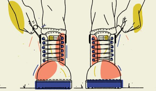
In fact, the origin of the term Boot as a startup term is related to footwear. Because computer startup begins with the hardware being powered on, at which point software is not yet working, it requires a bootstrapping program to bring it up. The action of booting up the software requires starting and running the software itself, which is reminiscent of an English proverb:
“Pull oneself up by one’s bootstraps.”
This means to achieve success through one’s own efforts and determination, much like pulling yourself up by your bootstraps. Since these two ideas are very similar, the bootstrapping program that starts up the computer was called a Bootstrap Loader, or Bootloader, for short, in the early days of computer development.
Introduction to Bootloader
The Bootloader, also known as the boot program, is a crucial component of computers and automotive controllers. However, because it often operates in the background, it is frequently overlooked. So, how does the Bootloader work exactly? Let’s take the PIC16 microcontroller in the figure below as an example.
According to the design of the microcontroller, it will execute instructions starting from address 0x000 in Flash memory when power is applied. That is to say, the first line of code is executed from 0X000 when the chip is powered on. As shown on the left, users can burn the entire user program to Flash memory by using the UART serial port, enabling the entire storage area to be used for the user program. However, this can be cumbersome every time the user program needs to be written. As shown on the right, if three lines of code are placed starting from 0X000, which are used to jump to the Bootloader section (i.e., jump 1 on the right-hand side of the figure), and then the Bootloader boot program is executed starting from the 0XF00 area, when started up normally, the Bootloader will jump back to the user program (i.e., jump 2 on the right-hand side of the figure) after completing its execution. Within the Bootloader program, special development routines or new user programs can be programmed, making it more user-friendly for development and programming.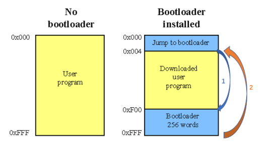
The specific details of Bootloader may vary slightly with different processors, but the overall logic and idea are the same. For example, for CPUs on PCs, the Bootloader also initializes hardware, loads the operating system kernel from the hard disk into memory, and then loads the operating system into memory. The operating system will further load the required applications from the hard disk into memory for execution. Generally speaking, Bootloader is the first line of code automatically executed by the processor hardware after booting up, which then boots up user code.
Flash Bootloader
As mentioned above, the advantage of Bootloader is mainly to provide convenience for the firmware update of user software. The traditional controllers in the automotive industry are highly embedded systems, and there are software update needs for various controllers from development to mass production to after-sales service. Bootloader is just the right tool to complete the task of updating controller software. This Bootloader for the purpose of updating software is widely known as Flash Bootloader (FBL) in the automotive industry. It is mainly used for the software update of traditional embedded systems such as MCUs.
In fact, Flash Bootloader should be regarded as the second program booted up after Bootloader. The first Bootloader that is booted up will determine the ECU state, and then start the application program or enter the Flash Bootloader based on this state. Due to concise expression or fuzzy concept, in many actual working situations, people often confuse Bootloader and Flash Bootloader. We can maintain communication coherence according to the situation, but we should be clear about the difference between the two in our minds.
In actual applications in the automotive industry, Bootloader is often subdivided into Primary Bootloader (PBL) and Secondary Bootloader (SBL). SBL is closer to Flash Bootloader. The following figure shows a common relationship schematic diagram between PBL, SBL, and MCU storage.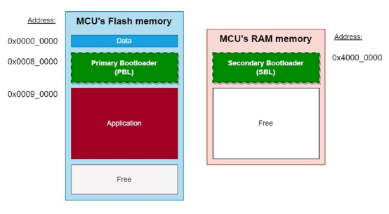
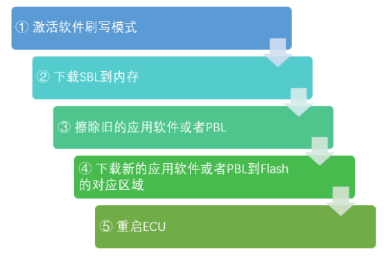
PBL plays a role in bootstrapping application software. PBL is stored in the Flash of the MCU chip, and it is generally pre-programmed in the factory. After the chip is powered on or restarted, PBL is the first batch of code executed. When software needs to be flashed, PBL can communicate with an external diagnostic tool using a unified diagnostic service (UDS) based on a underlying bus protocol such as CAN or Ethernet. After verifying the diagnostic tool’s permissions, PBL downloads the Secondary Bootloader (SBL) to the MCU’s RAM memory, which is then used to flash the software. SBL includes all the services provided by PBL, as well as a Flash driver and some additional UDS services. Upon UDS trigger, SBL will use the Flash driver to erase the old software and write the new software to the corresponding storage area, as shown in Figure 4:
To prevent the application software from being accidentally overwritten or deleted, Flash Driver is generally not included in PBL and cannot directly operate Flash memory. Every time software needs to be flashed, the SBL that contains the Flash Driver is reloaded from the diagnostic tool into the memory. This division of labor between PBL and SBL has the following benefits:
-
Prevent the application software from being accidentally overwritten during normal operation.
-
Improve network security. Every time the SBL is downloaded from the diagnostic tool, a secure authentication mechanism can ensure that only legitimate diagnostic tools can trigger the flashing process.
-
The SBL can also update the PBL in a reverse way, thus improving the overall flexibility of the bootloader.
SoC boot and flashing processThe Flash Bootloader mentioned above is for traditional highly embedded systems. However, it is believed that more and more high-performance computing chips are being popularized in cars and the solutions for the central computer in cars are also endless. For these high-performance computing chips, the industry commonly refers to them as SoC (System on Chip). The boot and flash solutions for SoC are similar to those for MCU. However, due to its more complex internal storage management system and internal bus, the specific implementation of boot has slight differences from MCU, and its details are closer to the familiar personal computer. The overall boot process is shown in the following figure.
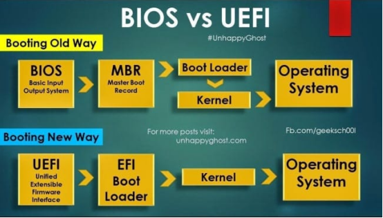
The boot of traditional computers generally adopts the BIOS boot in the upper part of the above figure. BIOS stands for Basic Input Output System, which is the first encounter between computer hardware and software. The code of BIOS is usually embedded in the EEPROM of the computer’s mainboard. BIOS can complete the basic self-test after the computer is powered on and instruct the computer on how to perform basic functions, such as booting and keyboard control. Boot parameters can also be configured in BIOS. Yes, that’s why we used to select booting from CD-ROM or hard disk in BIOS when reinstalling the computer system. Then BIOS will call the MBR (Master Boot Record) from the starting position of the hard disk, pull up the bootloader according to its partition table, and then call the operating system kernel, followed by the operating system and applications.
Of course, the design of BIOS has been around for years. Nowadays, the computer produced basically uses UEFI (Unified Extensible Firmware Interface), and the high-performance computing units in cars are the same. From the perspective of functional implementation, UEFI can be considered as an upgraded version of BIOS.
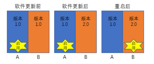
UEFI is a micro operating system. It loads the bootloader in memory and then executes additional operational programs. As a micro operating system, UEFI runs on firmware and supports more functions than BIOS, including security functions such as system verification. The most crucial difference is that UEFI supports a larger addressing space and can run in 32-bit or 64-bit mode (BIOS only supports 16-bit). In other words, UEFI can support larger hard disks or network sharing and has a faster boot speed.Due to the fact that SoCs generally use file system-based operating systems, software can be upgraded via the file system. In addition, since UEFI has a more flexible boot partition, high-performance computing platforms in cars generally support A/B partition upgrades. This means that while the A system is running, the redundant B system is quietly upgraded, the installation is completed after the upgrade, the SoC is restarted, and then switched to the B system. The overall process is shown in the following figure.
Challenges of Car Controller Bootup
At the beginning of the new year, everything starts anew. The beginning stage of each year has a significant impact on the whole year. The same is true for car controller bootup. A good start is half the success. Due to the importance of the bootup process, there are also many challenges that need to be resolved through the bootup process. The most prominent challenge is related to information security and bootup time.
Information Security Challenge of Bootup
A year’s plan starts with spring. Imagine if someone secretly changed the flag you set for your child during the Spring Festival period, and then your child followed this fake flag to act. If the flag was malicious, wouldn’t it be a big problem? The same is true for car controllers. If the bootloader or operating system loaded during the bootup process is maliciously replaced, the defense will be broken.
To meet this challenge, a secure boot mechanism is introduced during the bootup process. Its purpose is to verify the legality of the system signature before the system starts up, in order to determine the legality of the system to be started up. If the system is legal, the system will continue to be loaded and launched. If it is illegal, an error will be reported or automatically rolled back to the last legal system. Due to the difference in architecture between traditional embedded MCUs and high-performance computing chips in SoCs, there are slight differences in implementing secure bootup. As shown in the figure below, MCUs generally use an embedded HSM (Hardware Security Module) to store keys and verify signatures. SoCs generally use a TEE (Trusted Execution Environment) architecture to obtain keys and verify signatures. The two chip architectures adopt different strategies for security based on the chip architecture, but their goals and effects are the same.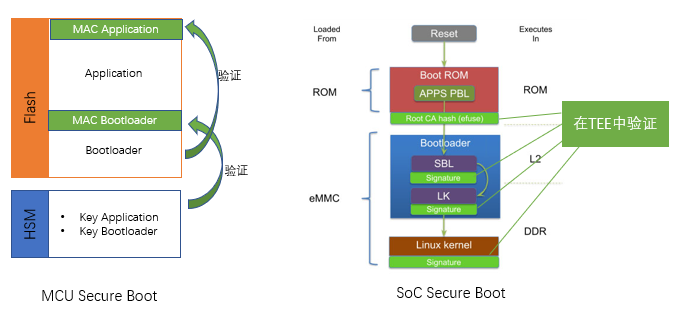
Challenge of Boot Time
With the development of in-vehicle computing platforms, the hardware resources that need to be managed are becoming increasingly abundant and complex. This makes the data that controllers need to load during startup larger, and the number of devices that need to be initialized also increasing, resulting in longer startup time. It’s like 20 years ago, Nokia phones could be booted up in a few seconds, while nowadays it takes dozens of seconds or even a minute or more for smartphones to boot up. According to industry observations, the normal startup time of several popular SoC products is rarely less than 10 seconds, and if the secure boot process is added, the startup time will be even longer. Some controllers even require nearly a minute from power-up to the start of upper-layer application functions.
In-vehicle applications are also very sensitive to boot time. For example, the backup camera that everyone is accustomed to nowadays. We usually get into the car, fasten our seat belts, start the car, and shift into reverse, hoping that the camera image will appear on the center console. Imagine if the entire startup time takes a minute, then we will have to wait for dozens of seconds inside the car or even drive blindly without assistance. Such user experience would be very poor.
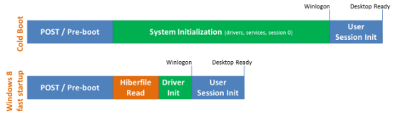
To meet this challenge, in-vehicle controllers or computing platforms often introduce a sleep mode. This is similar to the sleep mode of our computers, which stores the contents of memory that would be lost due to power failure into the hard disk, and the next time it starts, it reloads all the contents into memory, instead of using the flow of loading the bootloader from UEFI to the kernel and then initializing them again. This method enables the controller to stay in low-power mode for a long time and can start working quickly when it needs to be awakened. Of course, this requires extra space on the hard disk to store memory data during hibernation. Taking the schematic diagram of Windows 8 below as an example, traditional cold startup takes a lot of time to initialize the system, but when starting up from sleep mode, only the hibernation data (Hiberfile) on the hard disk needs to be loaded into memory, and the user login can begin.
 #
#
Meanwhile, besides Sleep mode, the controller can also optimize the secure boot strategy to reduce boot time. Under certain circumstances, the controller can be allowed to pull up the Bootloader, operating system, and application to record their relevant data such as the start-up signature and fingerprint. After the system is correctly installed and working, TEE conducts a recheck for the legal operation of the system in the background. If it’s illegal, the system enters a corresponding secure mode. This method may reduce security but shorten boot time compared with first verifying, then starting the system. According to the analysis of the whole-vehicle security structure, some relatively secured controllers (such as local controllers disconnected from the outside network) can adopt this strategy.
Of course, the development of products is multidimensional rather than unidimensional. The start-up of the automotive controller should also be selected and developed according to multifaceted standards. It’s similar to that traditional non-intelligent phones started up fast and safely with fewer viruses but were eventually replaced by the now-lengthier-lasting, riskier, intelligent phones. During the Spring Festival, the intelligent TV everyone watched at home is also true. In the emerging trend of automotive intelligence, the start-up process will undoubtedly be continuously balanced, made more intelligent, efficient, and secure.
References:
-
https://buildstorm.com/blog/automotive-bootloader-fbl/
-
https://www.embitel.com/blog/embedded-blog/what-is-flash-bootloader-and-nuances-of-an-automotive-ecu-re-programming
-
https://baike.baidu.com/item/Bootloader/8733520
-
http://www.oz1bxm.dk/PIC/bootloader.htm
-
https://www.timesys.com/security/secure-boot-snapdragon-410/
This article is a translation by ChatGPT of a Chinese report from 42HOW. If you have any questions about it, please email bd@42how.com.