
Author: Zeekr Software and Electronic Center, Wen Long
The current passenger car market is generally developing towards electrification and intelligence. With electric and intelligent development, the automotive thermal management system is becoming increasingly complex, with a greater impact on automotive safety, intelligence, comfort, and energy conservation. Thermal management has become one of the most important systems in new energy intelligent vehicles.
Under the new trend of intelligent experience, traditional thermal management control systems must also master new methodologies, achieve functional expansion, architecture upgrades, and apply new technological concepts such as whole vehicle services, digital twins, and machine learning to make the thermal management system more intelligent and proactive, enhancing its safety, intelligence, comfort, and energy conservation performance.
The control objects of the new energy thermal management system mainly include cooling fans, water pumps, water valves, refrigerant valves (on-off valves, electronic expansion valves), and electric compressors. The traditional development method of thermal management control system requires a lot of calibration experiments to complete the algorithm control and optimization of each component. In the current fiercely competitive environment, the development cycle of whole vehicle projects has been shortened from five years to three years, and sometimes even two or one year. Obviously, if we follow the traditional development method, the project requirements cannot be met. We must spend higher costs to complete the project development. Many times we choose to package the environment cabin or do reverse season experiments.
So, how can we efficiently complete the algorithm iteration and optimization of the thermal management control system? We borrowed the methodology of digital twins and introduced virtual calibration technology. For example:
1) Predict the optimal solution of the target pressure of the condenser fan and control the fan with a PI controller;
2) Predict the compressor speed for the passenger cabin cooling target outlet temperature and perform feedforward control;
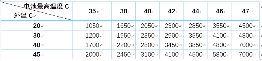
3) Predict the compressor speed for the target water temperature of the battery as shown in Table 1 and Table 2 and perform feedforward control, as well as evaluate the control time required for scheduled charging and preheating;
4) Predict the working energy consumption of the thermal management system under different working conditions and optimize the mode management control algorithm, etc.
Table 1 Driving air conditioning virtual calibration compressor speed (rpm) feedforward value
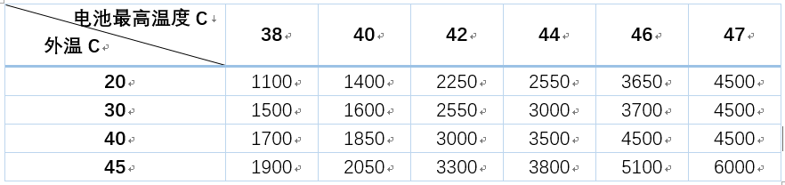
Table 2 Super fast charging virtual calibration compressor speed (rpm) feedforward value
 # Digital Twin Technology in Smart Manufacturing Sector
The concept of digital twin was first applied by the US National Aeronautics and Space Administration (NASA) in the Apollo project to simulate and analyze the flight status of spacecraft and assist ground control personnel in making correct decisions. Siemens believed that the components of digital twins include: product digital twin, production process digital twin, and equipment digital twin, which can completely and realistically reproduce the entire company. In recent years, digital twin technology has been increasingly popular and has garnered much attention from both inside and outside of the industry. Since the concept was proposed, digital twin technology has been rapidly evolving, and has played a huge role in the design, manufacture, and service of products. Digital twins use various digital means such as design tools, simulation tools, and Internet of Things (IoT) virtual reality to map various attributes of physical devices into virtual space, forming a digital mirror that is separable, replicable, transferrable, deletable, and can be repeatedly operated. This greatly accelerates the operator’s understanding of the physical entity, and makes many previously inaccessible operations due to physical conditions, such as simulation and virtual assembly, an accessible tool, inspiring people to explore new ways to optimize design, manufacture and service.
Here is a small case to illustrate how to apply virtual calibration technology to obtain target values for passenger cabin refrigeration compressor speed feedforward control. We know that the control requirements for target air temperature are fast, accurate and stable, and most of them adopt feedforward PID control method. Control = feedforward value + PID, and feedforward actually uses the object features, belonging to open loop control. The advantage is to improve system response speed and reduce feedback control pressure. If the object features are unclear, feedforward cannot be used. The traditional approach is to conduct an environmental model test in the environment cabin, obtaining the compressor speed feedforward value at different air volumes and target air temperatures under different environmental temperatures. This work would take about 50-60 hours, or about 7 days of test time to complete, with environmental modeling costs at around 15W-18W RMB (estimated preferential price) based on 3000 RMB/h. The new idea is to use digital twin technology to generate detailed physical modeling of the controlled object and couple it with vehicle thermal management control software to predict the compressor speed under different working conditions. This method, combined with modeling time, only takes a total of 3-5 days to obtain the desired prediction results. In summary, traditional thermal management methods rely heavily on vehicle, environmental model and other resources, but using digital twin technology can perform predictive analysis and optimization of the controlled object in the early stages of project development, achieving the goal of reducing the product development cycle and saving development costs.
Introduction to Virtual Calibration Technology Used in This Project
The first step is to organize the necessary component performance parameters and SPC files, as well as to comb the thermal management system architecture.
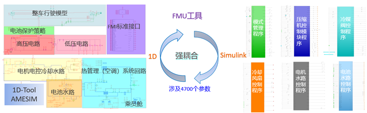
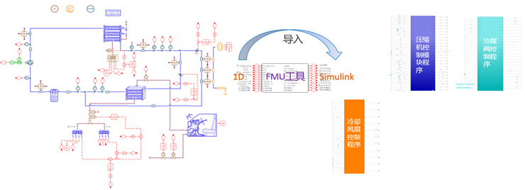
The second step is to build the corresponding physical model based on the requirements. Here, it is emphasized that the physical model must be simplified accordingly. The complete physical model of thermal management is shown in Figure 1. However, this work only involves the circuit of the thermal management air conditioning system, and the control model involves three control modules: compressor, refrigerant valve, and cooling fan. In order to ensure calculation speed and prediction accuracy, the model needs to be simplified. The final simplified physical model is shown in Figure 2.
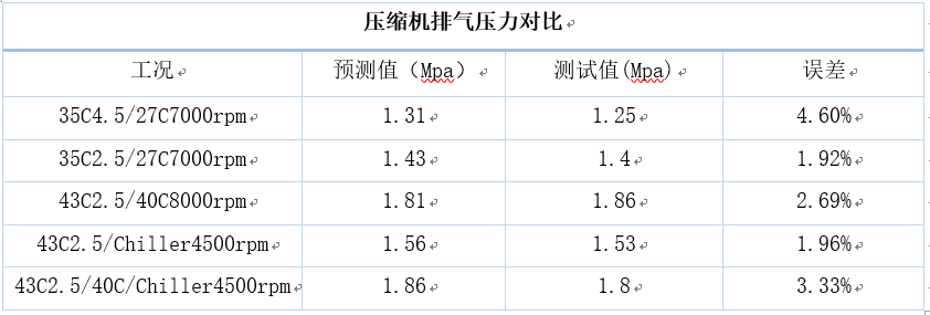
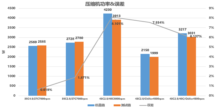
The third step is to calibrate the physical model. When calibrating the model, it is necessary to focus on the flow resistance of each component and pipeline, the heat exchange of the condenser and evaporator, and the calibration of the compressor volumetric efficiency, mechanical efficiency, and adiabatic efficiency. The accuracy of the thermal management air conditioning system model built using AMESIM is shown in Table 3 and Figure 3.
The fourth step is to import the AMESIM model, exported in Co-simulation mode, into the SIMULINK model through the FMU tool. This ensures the accuracy of the model solving. The thermal management air conditioning system model is solved using the AMESIM solver, and the control model is solved using the SIMULINK model. The iteration time step is set according to the actual vehicle control, which is set to 0.1 s in this work, and the data exchange involved is completed in the SIMULINK model file.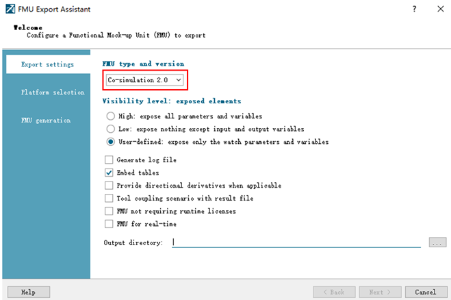
Here is a brief introduction to what FMU/FMI is. In various fields such as the automotive industry, aviation, and electromechanical equipment, different applications and modeling systems exist to solve different problems. In order to simulate the entire system, it is often necessary to interact between different simulation programs, and the integration of the system must enable simulation environments from different vendors to collaborate in order to complete debugging. This has created a demand for model interaction, but there is no standardized interface. Consequently, FMU/FMI was developed to address this issue. It is a tool-independent standard for supporting the interaction of dynamic models and joint simulation. It is used to solve the issue of model interoperability in the automotive industry. Initially funded by the European Union through the Modelisar project, Daimler was responsible for the project, and the first version was released in 2010. Improved versions were subsequently released in 2014, and development was actively led by the Modelica Association.
(1) FMI is an acronym for Functional Mock-up Interface, which means functional model interface. It is a tool-independent standard. As the version of the model exchange specification, FMI defines a standardized interface between the system simulation environment and the system simulation model. It supports dynamic models’ interaction and joint debugging through the fusion of XML files and compiled C code.
(2) FMU is a defined external format and compressed file (*.fmu) of a system model, which includes XML format interface data description and functions (implemented using C code or binaries). FMU refers to software components (modules) developed using the FMI interface.
FMU operation mode: (1) used for model interactions, with the intention that a modeling environment can generate C code for the dynamic system model in the form of input/output modules to be used by other modeling environments. The model (without a solver) is described using differential, algebraic, and discrete equations, including time, state, and velocity. (2) Used for collaborative work, which is aimed at coupling two or more models and solvers in a collaborative work environment. Data exchange between subsystems is limited to discrete communication points. During the time between two communication points, subsystems solve independently using their respective solvers. The main algorithm controls data exchange between subsystems and all synchronization from the simulation solver. This interface allows for standard and advanced main algorithms, such as the use of variable communication steps, higher-order signal extrapolation, and error control.FMI/FMU can achieve communication between software such as Amesim, GT, Matlab, Adams, Motion recurdyn, Labview, avoiding complex interface settings and software barriers. Additionally, only using GCC compiler can complete the compilation without relying on software such as VS.
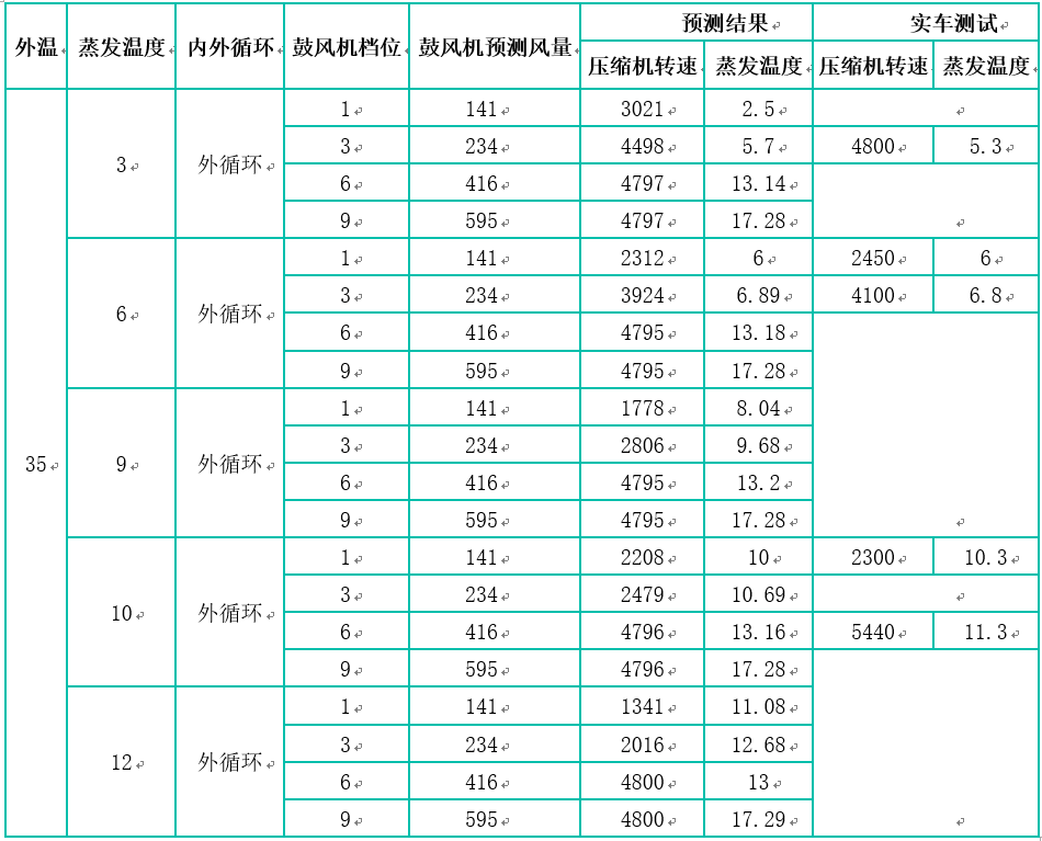
Finally, the full operating condition scan is performed in the Simulink control model to obtain the corresponding compressor speed feedforward by changing the input conditions (ambient temperature, target evaporation temperature, blower air volume, internal/external circulation ratio). Table 4 shows the comparison between some predicted results and actual vehicle test results. The analysis indicates that the error between the two is very small and the results can be used to predict the compressor feedforward calibration value.
In the trend of intelligent experience, integrating some new methodologies into the development of traditional thermal management control systems can greatly assist project development. This article briefly introduces some of the application scenarios of virtual calibration technology in the development of thermal management control systems. By using this technology to realistically replicate the performance characteristics of actual vehicles, algorithm iteration and optimization of thermal management control systems can be completed efficiently, achieving the goal of meeting project development requirements and saving project development costs.
-END-
This article is a translation by ChatGPT of a Chinese report from 42HOW. If you have any questions about it, please email bd@42how.com.