Author: Zhu Yulong
After the launch of the G9, there has been a lot of discussion about 800V. From the perspective of value, the main changes come from SiC modules, 400/800V boosting circuits, and the design of thin-film capacitors (insulation treatment after voltage resistance changes). I want to showcase a dismantling of the Japanese and Korean technology geek.
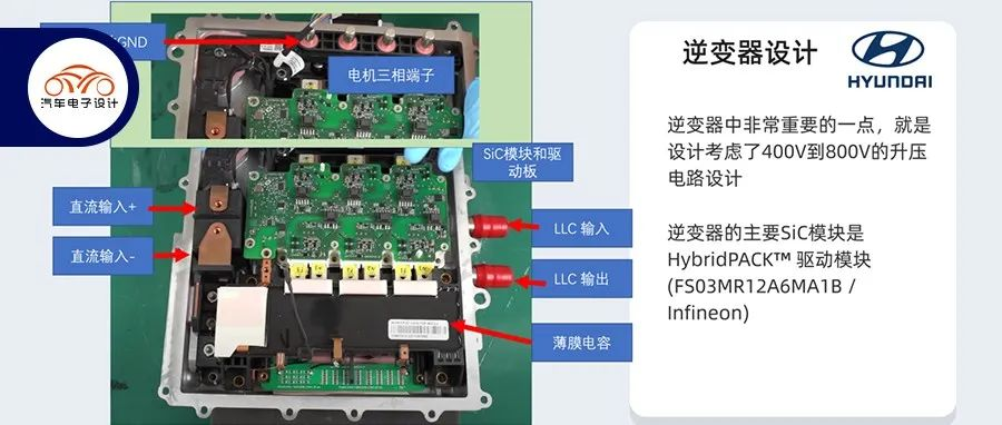
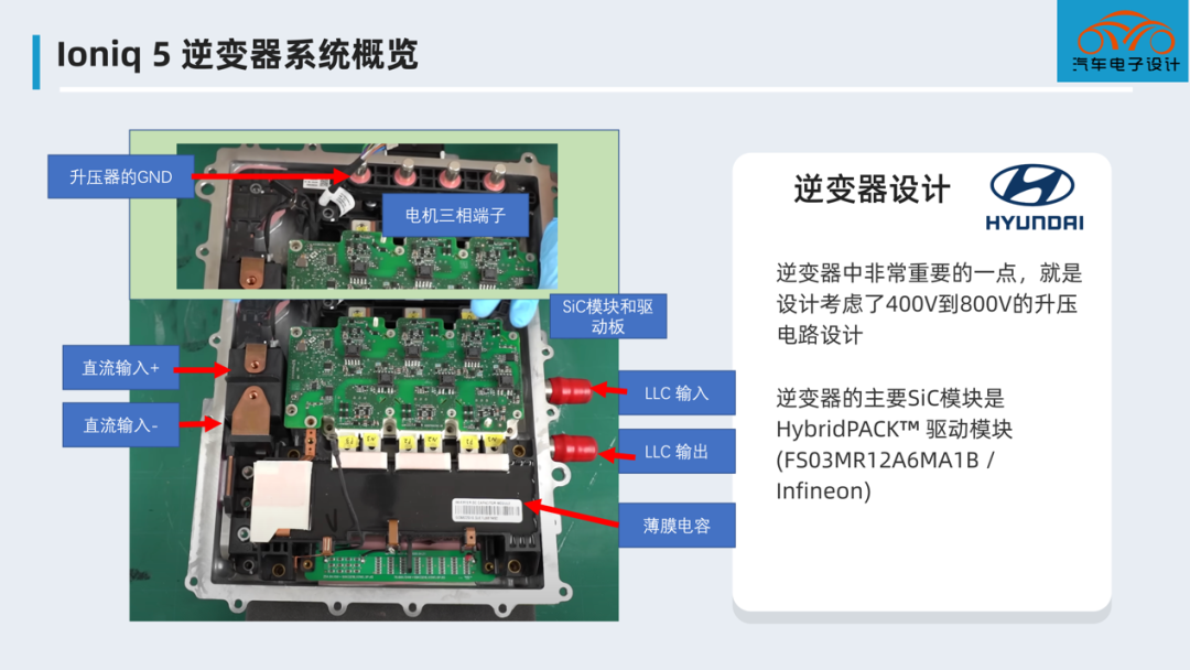
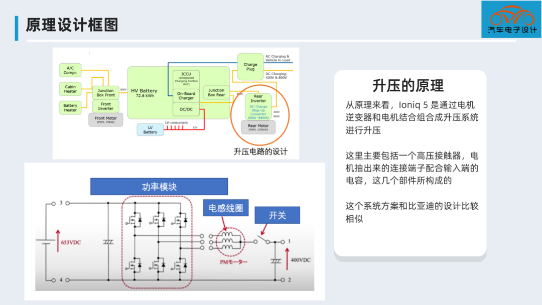
In the following all-silicon carbide inverter, the main components revolve around the HybridPACK™ drive module (FS03MR12A6MA1B / Infineon), and the inverter uses the motor’s inductance as a boosting chopper to boost under the condition of 400V DC input charging.
Note: I am thinking about making some dismantling and analysis videos in the future, which requires physical specimens and ideas with friends.
Dismantling of the entire inverter system
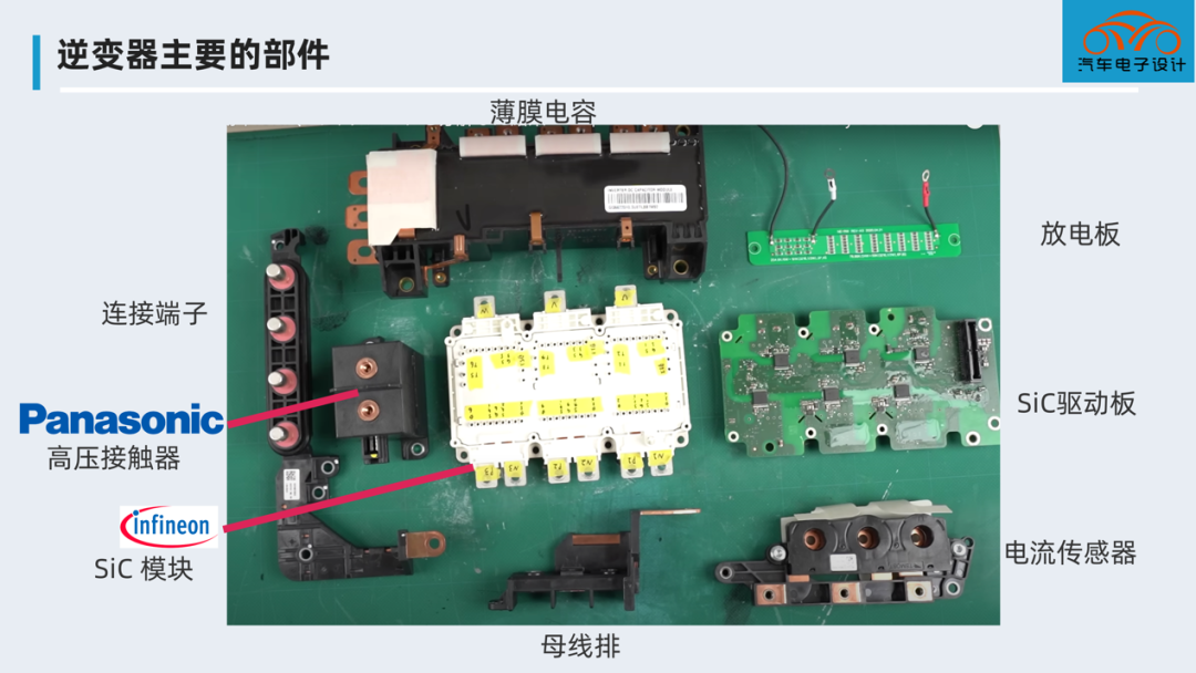
The design of this inverter is basically similar to what everyone knows. The only major change is the 800V system. Figure 2 shows an overview of the main components: the control board is on the back, mainly including film capacitors, SiC modules, drive boards, discharge boards, busbars, high-voltage contactors, current sensor assemblies, and connecting terminals.
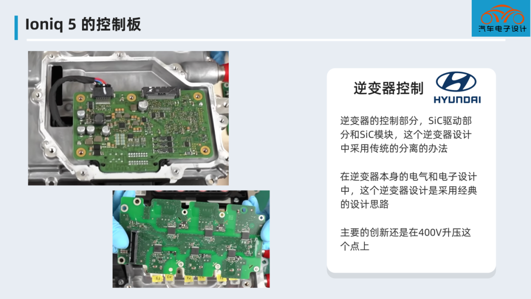
Below is the control board. The design of this inverter is very similar to the overall electrical architecture of the IGBT 400V inverter we see. The control part of the inverter is independent, and it is also possible that EMC interference is considered. The SiC drive part and SiC module are as close as possible. The control board and SiC drive board are connected by one row of connectors. In this inverter design, the traditional method is used to separate the electrical and electronic design of the inverter itself. The main innovation is still in the 400V boosting point.
The following figure shows the current sensor assembly and high-voltage contactor, with insulation paper used for insulation.
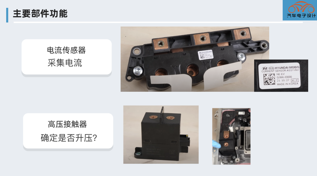
Design Principle
From a technical standpoint, the Ioniq 5 uses a combination of a motor inverter and a motor to create a boost system for boosting. This mainly includes a high-voltage contactor, connection terminals for the motor with input capacitors, and a system composed of these components that is similar to BYD’s design.
It should be noted that in addition to the Y capacitor, there is a 400V film capacitor (used for boost) and an 800V film capacitor for filtering.
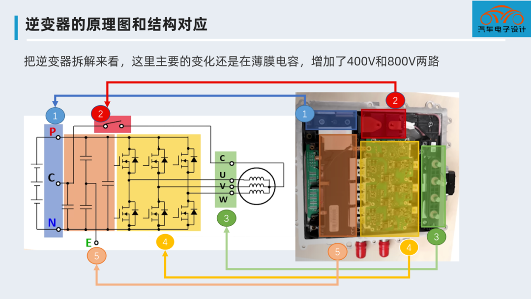
The film capacitor not only functions as a capacitor, but can also be scanned to find that it is actually a composite product of a capacitor and a busbar. The PN two terminals of the 6 inputs of the 400V and 800V SiC modules are integrated into it.
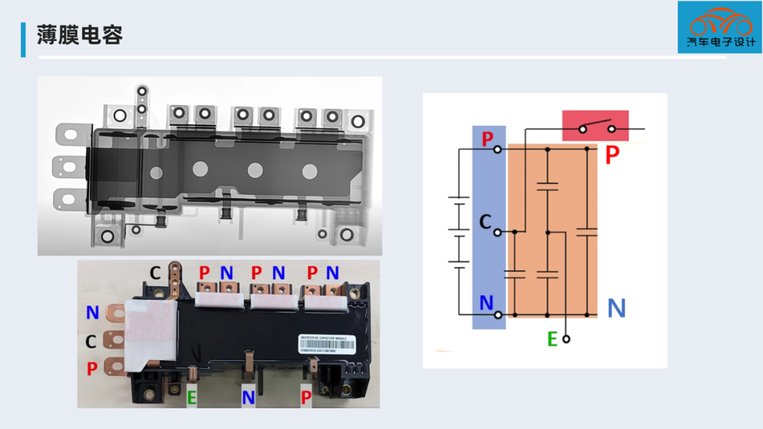
This is a preliminary conclusion that the SiC inverter design of this rear-drive system is very innovative.
In summary, there is not much to say. Maybe it would be more enjoyable to analyze these components with the video. (This is also why I am trying to make it more visual through video). Currently, when designing 400V to 800V boosting circuits, the possibility of referencing this design is relatively high. In actual large-scale use, the effect is still very good.
This article is a translation by ChatGPT of a Chinese report from 42HOW. If you have any questions about it, please email bd@42how.com.