Author | PanJiang
Previous articles:
Intelligent Chassis Series (1) | Overview: Yesterday, Today, and Tomorrow of Intelligent Chassis
Intelligent Chassis Technology (2) | Development Overview of Automotive Braking Systems
Since the birth of the automobile, the braking system has played a crucial role in vehicle safety. The most primitive form of braking control was through the driver operating a simple mechanical brake device to generate braking force. At that time, the vehicle’s weight was relatively small, and the speed was relatively low, and mechanical brakes satisfied the vehicle’s braking needs.
With the development of science and technology and the automotive industry, especially the development of military vehicles and military technology, there have been new breakthroughs in vehicle braking, and hydraulic brakes have become another major innovation after mechanical brakes. At the same time, as vehicles have become heavier and heavier, brake boosters have been widely used. The vacuum booster, which works with the traditional engine, has become a standard configuration for passenger cars.
Although under the wave of automobile intelligence and electrification, line-controlled booster such as eBooster is gradually eating away at the market share of vacuum booster, the enormous cost advantage still makes vacuum booster far ahead in the market share of passenger cars. According to forecasts, vacuum boosters still account for more than half of the passenger car market share in 2028.
This article will introduce the vacuum booster, including:
-
Hydraulic Brake System and Vacuum Booster
-
Working Principle of Vacuum Booster
-
Vacuum Booster and Stability Control System
Hydraulic Brake System and Vacuum Booster
Because medium and heavy-duty commercial vehicles have a large full load weight and high brake force requirements, they generally use a structurally complex air brake system to assist the driver’s braking. Air braking uses compression control as the braking source, with the brake pedal controlling compressed air to enter the wheel brake device to achieve braking. For long wheelbase, multi-axle, and semi-trailer and trailer vehicles, air braking has unique advantages in achieving asynchronous distribution of braking, but its shortcomings are also more evident: its braking characteristics are not as smooth as hydraulic brakes, and driving comfort is affected.
 The braking system of passenger cars and light commercial vehicles mainly uses hydraulic pressure as the transmission medium. Compared with pneumatic braking systems, hydraulic braking systems have relatively simple structure and flexible layout, which can not only meet the braking requirements of the whole vehicle, but also improve driving comfort due to their excellent braking characteristics.
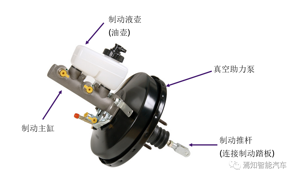
The hydraulic braking system of a typical passenger car consists of the following parts, among which the vacuum booster is the key to increasing braking force for drivers.
- Brake pedal
- Vacuum booster
- Brake fluid
- Brake pipes
- Brake master cylinder
- Brake wheel cylinder
- Wheel brake (disc or drum brake)

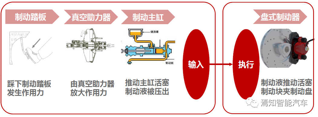
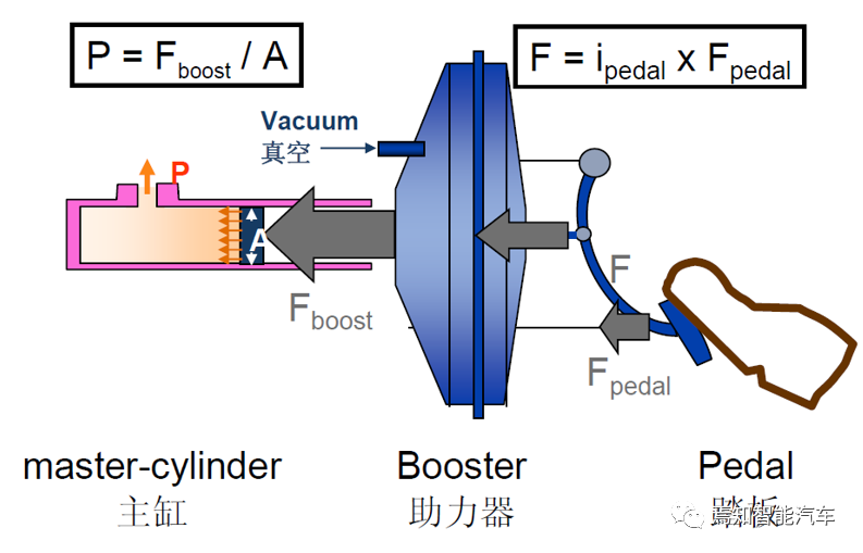
Taking disc brakes as an example, when the driver steps on the brake pedal, the lever action transmits the pedal force to the vacuum booster through the first stage amplification. The vacuum booster then transmits the braking force to the master cylinder through the second stage amplification. The brake fluid in the master cylinder is pushed into the wheel cylinder, producing greater braking force under the action of pressure, pushing the caliper on the wheel to clamp the brake disc, thus achieving the braking effect.
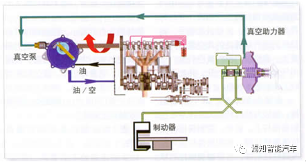
The key to the normal operation of the vacuum booster is to have a stable vacuum source. Vehicles equipped with gasoline engines generate high vacuum pressure in the intake manifold, which can provide sufficient vacuum sources for the vacuum-boosted braking system. However, for diesel engine-driven vehicles, since the engine adopts a compression ignition cycle instead of spark ignition cycle, the intake manifold cannot provide the same level of vacuum pressure. As a result, they need to install a vacuum pump to provide the vacuum source for the vacuum-boosted braking system.
Some readers may have had the driving experience that the brake pedal is hard to press and cannot be depressed when the engine is not running, but it becomes lighter and provides greater braking force when the engine is started. This is because the vacuum booster can only operate normally when it has a vacuum source after the engine is started.
In addition, for gasoline direct injection engines (GDI) designed to meet high emission environmental protection requirements, they cannot provide the same level of vacuum pressure in the intake manifold to meet the requirements of the vacuum power braking system. Therefore, a vacuum pump is also needed to provide the vacuum source, as shown in the figure below.
 In normal circumstances, the vacuum booster assists the driver in braking. When the booster fails, the hydraulic system can still generate a certain degree of braking force by manual effort.
Working Principle of Vacuum Booster
When the engine is running, the pressure inside the intake manifold is lower than atmospheric pressure, creating a certain amount of vacuum. This pressure difference is sucked into the front chamber of the vacuum booster through the vacuum hose, reducing the pressure in the front chamber below atmospheric pressure. When the brake pedal is depressed, the intake control valve in the rear chamber of the booster opens, the rear chamber is pressurized to atmospheric pressure, and the pressure difference generated is used to push the pushrod of the master cylinder forward, thereby pushing the brake fluid in the master cylinder into the brake line to generate braking force on the wheels. Therefore, the brake pedal only needs to generate a small force to push the control valve pushrod of the vacuum booster and open the intake control valve in the rear chamber of the booster to form a vacuum assist. With a small amount of brake pedal force, the booster can generate a high braking line pressure and deceleration, effectively reducing the braking distance and improving safety.
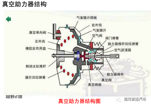
The operation of the control valve pushrod is crucial to the operation of the vacuum booster. As shown in the figure below, in the non-working state, the control valve pushrod return spring pushes the control valve pushrod to the right locking position of the locking piece, and the vacuum one-way valve is in the open state. The control valve spring makes the control valve cup tightly contact with the air valve seat, thereby closing the air valve port. At this time, the vacuum chamber and application chamber of the vacuum booster are respectively communicated with the outside through the vacuum chamber channel and the application chamber channel of the piston body through the control valve chamber, and are isolated from the atmosphere. After the engine starts, the vacuum degree at the engine’s intake manifold increases, and the vacuum degree of the vacuum chamber and application chamber of the vacuum booster also increase, and are in a state of being ready to work at any time.
 When braking, pressing the brake pedal amplifies the pedal force through the lever and acts on the control valve push rod. First, the control valve push rod return spring is compressed, and the control valve push rod and air valve stem move forward. When the control valve push rod moves forward to the position where the control valve diaphragm and the vacuum one-way valve seat are in contact, the vacuum one-way valve is closed. At this time, the vacuum chamber and application chamber of the booster are separated. At this time, the end of the air valve stem just contacts the surface of the reaction disk. As the control valve push rod continues to move forward, the air valve opens. After the outside air passes through the filtering air and enters the booster application chamber (right chamber) through the open air valve port and the channel leading to the application chamber, the servo force is generated. Due to the physical property requirements of the reaction disc material (rubber part) with equal unit pressure at all points of the force surface, the servo force increases in a fixed proportion (servo force ratio) as the input force of the control valve push rod gradually increases. Due to the limited availability of the servo force resources, when the maximum servo force is reached, that is, when the vacuum degree of the application chamber is zero (i.e., a standard atmospheric pressure), the servo force becomes a constant, and no longer changes. At this time, the input force and the output force of the booster will increase equally. When the brake is released, as the input force decreases, the control valve push rod moves backward, and the vacuum one-way valve opens. The vacuum chamber and application chamber of the booster are communicated, and the servo force decreases, and the piston moves backward. In this way, as the input force gradually decreases, the servo force will also decrease in a fixed proportion (servo force ratio) until the brake is completely released.
Vacuum Booster and Stability Control System
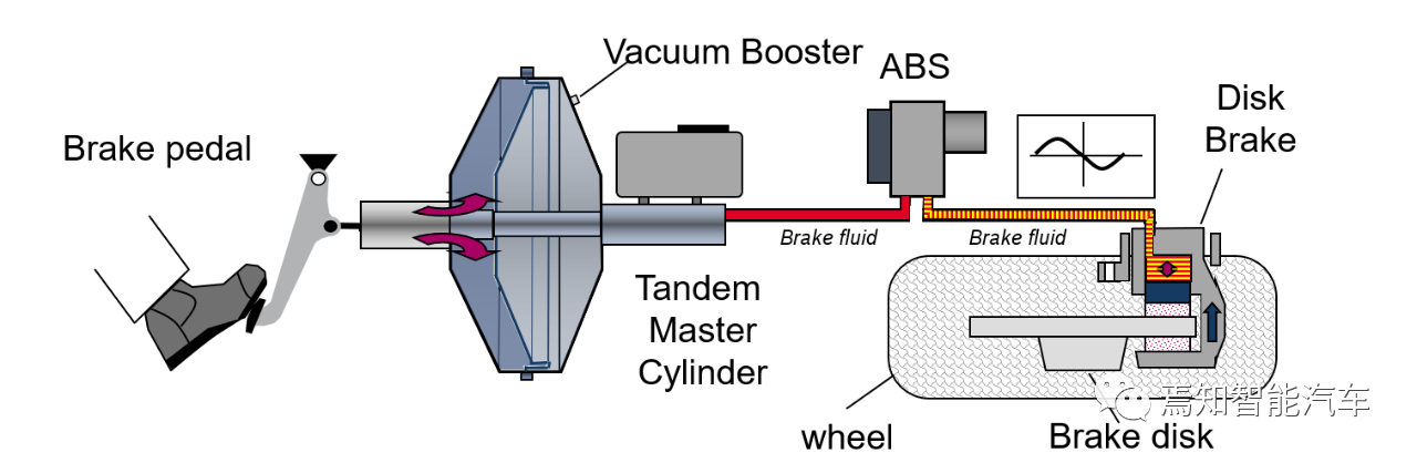
With the popularity of Anti-lock Brake System (ABS) and Electric Stability Controller (ESC), the vacuum booster naturally needs to realize compatibility with these stability systems to expand the overall brake system’s capabilities. The following is a layout schematic of the vacuum booster and ABS.
In addition, the vacuum booster’s boost capacity is usually affected by the following factors:
- Vacuum deficiency caused by limited size due to engine compartment space;
- Vacuum deficiency caused by driving at high altitudes;
- Vacuum deficiency caused by cold start conditions.
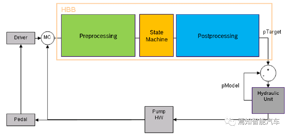
Since the ESC system has the ability to actively control the braking force of the four wheel cylinders, it can compensate for the insufficient capacity of the vacuum booster, and the vacuum booster’s assistance function HBB (Hydraulic Brake Boost) as the value-added function of the ESC system can assist in actively boosting during dynamic braking under specific driving conditions, and the basic principle is to amplify the driver’s braking request.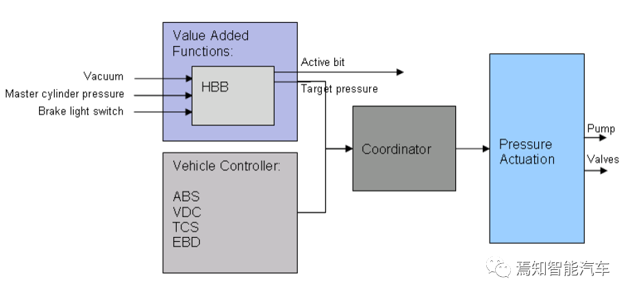
When the driver steps on the brake pedal, HBB is ready. During the preprocessing, HBB reads the driver’s brake request and amplifies it, then sends the calculated value to the state machine to trigger different HBB states according to the corresponding trigger conditions. When HBB meets the activation conditions, the target pressure value will be passed to the hydraulic control module through post-processing to control the pump speed and valve action. The speed of the pump will affect the pressure in the master cylinder, which in turn affects the driver’s braking request, brake pedal, and the driver himself/herself. The driver adjusts his/her behavior to adapt to the changes caused by the pump speed. This part of the control is closed-loop control, and the entire process is shown as follows.
In summary, for traditional fuel cars, the vacuum booster can not only meet the basic functions of the braking system, but also improve the braking stability in conjunction with stability functions, and its enormous cost keeps it competitive in the market. However, under the trend of electrification, the engine is replaced by a high-voltage motor and the vacuum booster has no stable vacuum supply source, which limits the use of the vacuum booster. In addition, the high requirements of intelligentization for the braking system further restrict the application of the vacuum booster, which requires the braking assist system to evolve.
This article is a translation by ChatGPT of a Chinese report from 42HOW. If you have any questions about it, please email bd@42how.com.