Preface
The purpose of adopting new technologies is not to reach the goal, but to achieve the results. There are many ways to reach the destination, but the shortest one is often narrow.
This article will analyze the evolution of Tesla’s electrical architecture from the perspective of technology requirements driving the development of the lowest level of vehicle electrical architecture, and the impact of semiconductor devices-based electrical architecture on the automotive industry. The article focuses on the difference between traditional fuse boxes and electronic intelligent fuse boxes, which does not mean that “electronic is necessarily safer”, but rather that “the upper limit of safety can be higher”.
To facilitate better understanding, the article will popularize some basic principles of vehicle electrical engineering, including fuses, relay principles, semiconductor device principles, and vehicle wiring harnesses.
The author believes that high-level autonomous driving technology will first land in commercial vehicles rather than passenger cars. Therefore, this article will analyze the impact of commercial vehicle electrical architecture and semiconductor devices on its development.
In the article “Get Rid of Fuses and Relays for Safer Autonomous Driving” published on February 19th, it was mentioned that Tesla Model 3, as the world’s first mass-produced vehicle to introduce area architecture, has completely eliminated low-voltage fuses and relays that have been used in vehicles for hundreds of years. This is an extremely bold and innovative design.
As mentioned earlier, the author believes that Tesla’s cancellation of low-voltage fuses and relays is a natural result of its overall electronic electrical architecture design, rather than the goal. Today we will further analyze this.
Evolution of Tesla’s Electronic Electrical Architecture
The evolution and trend of vehicle electronic electrical architecture have been widely discussed, and Tesla’s architecture evolution has basically followed this direction, only at a faster pace.
In June 2012, the first Model S was offline, and there was already a clear domain division, including power domain, chassis domain, and body domain. The ADAS module spanned the power and chassis domains, and the Center Display served as the central computing platform for the vehicle. In September 2015, the first Model X was offline, using the same topology as Model S, but adding network nodes for the gull-wing door functions.
In September 2017, the first Model 3 was offline. Its electronic electrical architecture was completely different from the traditional separated network architecture. It no longer distinguishes domains, but integrates cross-domain and cross-network segments using centralized computer control, which has basically reached the “area architecture” that Bosch believes in. The Nikkei Economic News believes that this has “led the industry by six years”.# The Radical Innovation of Tesla in Electronic and Electrical Architecture
Despite being Tesla’s consistent style, the fundamental reason for its radical innovation in electronic and electrical architecture is that traditional domain architecture can no longer meet the development of autonomous driving technology and the future demand for Software Defined Vehicles (SDV). This requires the decoupling of hardware and software and a powerful hardware foundation, otherwise SDV cannot be achieved.
The development process of Tesla’s architecture is also a process of reallocating functions. In this process, Tesla constantly takes functions from Tier 1 suppliers and develops them on its own. The most typical example is iBooster, which Tesla has modified and added its own strategies to. This ability and courage of Tesla are difficult for other OEMs to catch up. In Model 3, including autonomous driving and entertainment control modules, FBCM, LBCM, RBCM, thermal management, etc., all of them were independently designed and developed by Tesla. Tesla’s architecture has the following advantages:
-
All major modules are independent. Without Tier 1 suppliers, Tesla can design and innovate from the perspective of the overall vehicle electronic and electrical system architecture.
-
Many joint developments have been carried out even for independent modules. For example, iBooster can be directly improved through OTA to reduce braking distance without going through Bosch. This is very difficult for traditional OEMs because of the high risk.
-
Leading the “hardware preset + software paid” model. The hardware functions are extremely powerful, laying a solid foundation for the decoupling of software and hardware that SDV aims to achieve.
-
Hardware abstraction, functions are “extracted” from independent controllers and centralized to the Center Display. From a functional perspective, software and hardware are separated, and this “virtual hardware” can be redefined by software as per the changing demand without modifying the hardware itself.
-
The regional architecture achieves cross-domain and cross-network segment, completely breaking the traditional vehicle design concept, with higher flexibility, stronger definability, lower system cost, and faster iteration speed. For example, Tesla’s Model 3 FBCM is responsible for power distribution, left front light control, air conditioning control, thermal management, etc., spanning traditional body, cabin, chassis, and power domains.
With the support of the brand new architecture based on Tesla’s unparalleled OTA technology, Tesla’s car becomes a “living car” that brings new excitement to users every time after OTA, making it always new and fresh.
So, why did Tesla get rid of fuses and relays, and what is the relationship between this and the evolution of Tesla’s electronic and electrical architecture? Do not worry, after reading the entire article, I believe everyone will have their own answers.Considering that many developers working on automatic driving may not be familiar with the vehicle electrical system, we will briefly introduce the basic principles of vehicle electricity to help you better understand the content that follows. This part may seem tedious, but it will help you understand the analysis in the subsequent sections.
Basic Principles of Vehicle Electricity
-
The source of vehicle power is the generator (DC-DC in the case of new energy vehicles, converting high-voltage battery to low-voltage 12V/24V) and the battery in parallel during startup, while the battery alone supplies power when the vehicle is not in start mode. Actually, after the vehicle starts, even if you remove the battery, the basic functions of the vehicle are not affected. This can be understood as jump start, which means that when the battery is dead, the vehicle can still operate normally if jump start is used to start it.
-
Electrical equipment in the vehicle has different power supply states according to usage requirements, which are generally divided by ignition switch positions (OFF, ACC, ON, START) – ACC gear is basically not included on modern ignition keys, however, the ACC power still exists. For example, when the key is not turned to the ON position, the windows cannot be adjusted, which is a functional limitation. However, when you turn off the key, as long as it is not removed, the music can still play, which is a user-friendly setting. At the moment you start the vehicle, the window lift will pause for a moment, and the wiper will also stop for a moment if it is still in operation. This will save battery power for the starter motor.
-
Different power attributes are controlled by the relays in the distribution box, and this logic was determined at the design stage, many of which are controlled by hard wire and cannot be changed by software. Just like when you turn the key from ON to OFF, many functions cannot be used because there is no power. Unless the wire is changed, the logic cannot be changed. This means that this part of the function does not support OTA.
-
The role of the fuse is to protect the wires, which means to prevent the wires from catching fire due to short circuits and eventually burning the vehicle down. Some of our friends may think that fuses protect electrical equipment, but in fact, this perception is incorrect. For example, if the electric rice cooker in your home is damaged, it causes a circuit breaker trip, do you think it is to protect your rice cooker? No, you just have to buy a new one. If the wires inside the wall burn out, you will have to knock down the wall. Which one do you think is more cost-effective?
-
Fuses and wires need to be matched and verified. The larger the fuse, the thicker the wire needs to be. People who have done home decoration should know that the air conditioner wire needs to be thicker, and the socket needs to be larger than normal. If the wire is too thin, and it burns out in the end, you may have to knock down the wall. However, don’t worry, your air conditioner will definitely not break.
-
There is a fuse in every circuit, but not every circuit can be independently controlled. Generally, the number of fuses is more than twice that of relays, which means that at least half of the circuits in the fuse box are not controlled. Remember this, it will be tested later.7. The function of the relay is as we learned in middle school physics, which is to control strong electricity with weak electricity. Of course, the strong electricity here doesn’t refer to high voltage, but rather large current. The ECU in the car is limited in its driving ability and generally cannot directly drive high-power loads. It only outputs control signals, which are then used to control the operation of the loads through the relays in the distribution box. Some ECUs come with built-in PCB relays, which can directly drive the loads, but they generally don’t have protection. Protection still needs to be achieved through fuses in the distribution box, which requires additional wiring. We will discuss this in more detail later.
-
Fuses and relays are passive components without status monitoring or fault diagnosis. The power supply of the fuses and control of the relays are both open-loop. It’s like your autonomic nervous system – your brain cannot monitor or control it, you cannot stop breathing and you don’t know your digestive status or blood pressure. So, imagine if you could control your own breathing, heartbeat, blood pressure, and digestion, you would become a superhuman. The same applies to your car.
-
There is another type of power source in the car called constant power, also known as KL30. It is directly connected to the battery through a fuse and is not controlled by anything. It is always powered, unless the battery is removed. Some of our partners who work with passenger cars may not know that commercial vehicles have two types of constant power – one is the same as that in passenger cars, which is directly connected to the battery; the other is the main switch constant power, which remains powered even in the OFF position. Of course, the main switch needs to be turned off after parking, otherwise the car may not start next time.
-
The battery capacity is always limited, so strict power management is needed for non-starting states to prevent the battery from depleting too quickly.
-
The power consumption of any device connected to constant power must enter sleep mode after the vehicle is parked and locked. At this time, the power consumption of the entire vehicle (static current) needs to be controlled at a very low level to meet the requirements of being able to start after long-term parking. Generally, OEMs require the entire vehicle to consume less than 15mA-20mA, which can still start normally after being parked for 2-3 months. So, don’t worry that your car won’t start after being parked for a month; the OEM has already taken care of this.
-
Even in new-energy vehicles with large-capacity high-voltage batteries, if the battery is depleted after parking, the power consumption of the entire vehicle comes from the battery. If the battery becomes depleted after a period of time, the vehicle will not start. Therefore, new-energy vehicles generally have strict requirements for sleep current.
You might ask why new-energy vehicles cannot automatically start the high-voltage battery to charge the battery when the battery is depleted. This is a great idea, congratulations, you and Musk with “first principles” thinking are thinking alike. However, besides Tesla, no one seems to do this. We will skip this for now and analyze it in detail later.
Two Different Electrical Architectures
The Electrical Architecture of Traditional Vehicles
Now, let’s take a look at the electrical architecture of traditional passenger cars.Most traditional vehicles have 2-3 distribution boxes, which are extremely simple in structure and belong to traditional electrical components. They don’t have any electronic components and look stupid, large, black, and crude. Inside, there are connectors, copper sheets, fuses, and relays, which are not advanced technologies. If you haven’t returned the physics textbook to the math teacher, I guarantee that you can understand the electrical schematic. Otherwise, it’ll be hard for the repair shop to maintain the car for you.
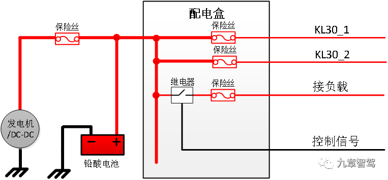
Without further ado, let’s take a look at the picture. After all, there’s no truth without pictures. The following figure is the engine compartment distribution box of a passenger car, which belongs to the primary distribution of the entire vehicle. All the power on the vehicle needs to pass through it, just like the distribution cabinet of a transformer substation in a residential area. Every household’s electricity comes from here.
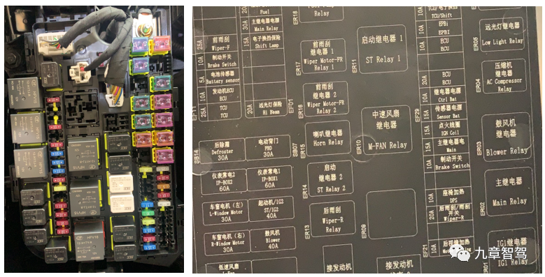
As we can see from the figure above, the traditional distribution box is indeed a distribution box, which implements the function of distributing the power of the entire vehicle, pure electrical in nature, without electronic components, programmable, and once the function is designed, it cannot be changed.
From the picture above, we can see that there are a total of 40 fuses and 19 relays in the traditional distribution box, which include almost all functions, such as ON gear, air conditioning compressor, blower, defrosting, instrument panel, window, wiper, horn, lighting, oil pump, gearbox, brakes, etc. If a fuse blows, your car may be out of action.
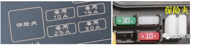
The vehicle OEM kindly printed all the functions of the fuse box on the cover of the fuse box, which is concise and clear, and even gave you a map of the location, so even a novice can understand it at a glance. There is a spare fuse on the side, and even a small clip to remove the fuse. This is just to make it easy for you to change a fuse when your car breaks down in the wilderness and rescue personnel ask you to check if a certain fuse is the problem. At first, you’ll probably be anxious, helpless, and at a loss, but the moment you flip over the cover of the fuse box, you’ll feel like you’ve found a treasure and be moved to tears. Instantly, a feeling of faith in a certain OEM rises from the bottom of your heart: “This car’s design is simply too good, too user-friendly. I’ll buy from them again next time.”
But wait, let’s take a look at the other brands. Actually, every fuse box is like this.
Now let’s take a look at its electrical schematics, and as long as you haven’t returned the physics textbook to your teacher, you should be able to understand it.
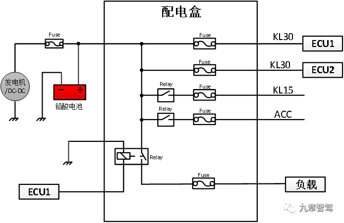 The constant power source directly from the fuse is known as KL30. Each one controlled by a relay has its own logic, with the ignition lock directly controlling OFF, ACC, ON, and START. For vehicles with one-button start functionality, the PEPS module is used to control them, still through relays, with no change to the principle.
Behind the first-level distribution is the second-level distribution, which is usually located in the driver’s cabin, thus also called the driver’s cabin distribution box. This box is relatively small, has many fuses, and has few relays. Being on the second level, the probability of failure is slightly lower, and the accessibility design is not as good, so it is not easy to find for non-professionals. The second-level distribution is like the distribution box at the entrance to your home. If there is a problem with the circuit in your home, the distribution box in your home will trip, but it will not affect the distribution in the neighborhood and will not affect the electricity consumption of other people’s homes.
As the distribution box contains only electrical components and no electronic parts or communication, this leads to the lack of fault diagnosis and control is open-loop both for the fuses and relays. For the entire vehicle, the distribution box is like a black box, impossible to monitor or diagnose. As long as you don’t detect a fault, there won’t be any faults.
So, if you are on the road and notice that only one of a car’s headlights is on, it is really possible that the driver does not know that one of the headlights is broken. Due to the inability to diagnose with no warning light, the driver will not be notified of a broken headlight. However, if the diagnostics can be connected to the network, the app will immediately remind you while already booking a nearby repair shop for you. Doesn’t that feel completely different? Suddenly, you will think “This money spent is totally worth it. Paying for software is awesome. I will renew my subscription next year.”
The Electrical Architecture of Tesla Model 3
Okay, after discussing the traditional architecture, let’s take a closer look at Tesla’s electrical architecture and see where their advantages come from.
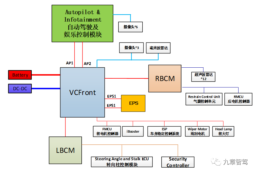
Compared to the traditional distribution architecture, Tesla’s architecture has the following advantages:
-
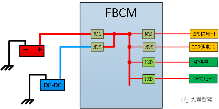
High reliability due to dual power supply + dual busbar input. Two input power sources enter FBCM(VCFront) from two independent busbars, while traditional distribution boxes have only single input, thus Tesla’s solution has higher reliability.
-
High reliability based on semiconductor devices for dual power supply. For single road open circuit fault for the dual power supply design (including dual power input and dual power output), the safety of semiconductor protection and fuses is the same, but for single road short circuit faults, the protection speed of semiconductor devices is much higher than that of fuses, thus making it safer as detailed in the previous article “Get Rid of Fuses and Relays for Safer Autonomous Driving,” so it will not be described again here.- Fusion of control and execution. The physical concept of the power distribution box is blurred, as FBCM, LBCM, and RBCM themselves are an ECU that also serves as a power distribution box. The functionalities of the two are fused, allowing BCM to control any load directly, which has significant implications that we will analyze in detail later.
-
Fusion of protection and control. Another advantage of semiconductor-based power distribution is that the line protection and control are fused. Protection is equivalent to control, and control is equivalent to protection. This is also of great significance, which we will further elaborate on later.
-
Another advantage of the fusion of protection and control is that each line can now be independently controlled. This means that each line can be programmed and controlled separately. This is a significant development, and it is important to memorize this for future reference.
-
Diagnostic function. Another advantage of semiconductor-based power distribution is that open-loop circuits can now be closed-loop. Each line can be monitored, diagnosed, and the information can be connected to the internet.
Now that we have covered the architecture, we can analyze the changes that have come with semiconductor-based power distribution replacing fuses and relays. First, we need to familiarize ourselves with some basic concepts, and I will explain them in layman’s terms so that everyone can understand.
Basic Principles of Fuses and Relays
Basic Principles of Fuses
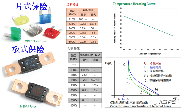
From the above figure, we can see some basic characteristics of fuses:
(1). There are fast-blow and slow-blow fuses. Small piece fuses used in cars are fast-blow and are suitable for low current situations; box and board fuses are slow-blow and are suitable for high current situations.
(2). Fuses rely on their own heating to melt and break the circuit to protect it, and are disposable and non-self-healing (self-healing fuses are very expensive and are rarely used in passenger cars, so we will not discuss them). After the fuse has melted, it needs to be replaced.
(3). The specifications of the fuse are not continuous, such as the commonly used 5A, 7.5A, and 10A. If you want 8.5A, you will not find it, and you can only go up and use a 10A fuse. It’s like choosing third-party liability insurance for 50,000 or 100,000. If you want 70,000, you won’t find it, and you can only buy 100,000.
(4). The specification of the fuse determines the protected current. If you use a 5A fuse, you should never exceed 5A in actual usage. It’s like buying insurance that covers 500,000. You should never challenge a luxury car worth several million because the amount exceeding 500,000 is not covered. Of course, if you buy third-party liability insurance that covers 3 million, then never mind what I just said.(5). Fuses rely on overcurrent heating to fuse and protect, and the fusing time varies greatly with the current. Taking fast-acting fuses as an example, 200% current can last up to 5s, while 350% is only 0.5s, 10 times faster.
(6). Since the protection of fuses relies on heating, the protection time varies with changes in ambient temperature. The hotter it is outside, the faster the fuse will melt, causing inaccurate protection. For example, the fusing time for 200% rated current of fast-acting fuses varies from 0.15s to 5s.
(7). Fuses can only protect against short circuits and are almost ineffective for overcurrent faults. As you may have noticed, all fuses are not protected against 110% current, such as a 10A fuse will never protect against 11A current.
(8). Unlimited short-circuit current poses two problems: First, the power supply voltage will be instantly lowered; second, it may cause ignition, and if there are flammable gases, it may be dangerous.
(9). The lifespan of fuses based on I2t is generally around 100,000 times.
- Design of Fuses Application:
(1) To reiterate, fuses are used to protect wire harnesses, not electrical appliances.
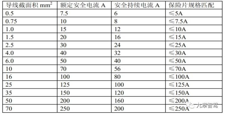
(2) Fuse design is the first step in vehicle electrical design: ① determine the fuse according to the load characteristics; ② determine the wire diameter according to the fuse; ③ design the entire vehicle wire harness according to the wire diameter. It’s like decorating a house. When you decide where to put the air conditioner, the decoration company can do the wiring.
(3) The margin of the fuse consists of four parts: ① 25% basic reduction, which may be reduced more depending on the load; ② temperature range, 10% reduction in high-temperature engine compartments; ③ round up the calculated results, if there is no such value, it can only be rounded up; ④ considering I2t, it may need to be upgraded to a larger fuse, otherwise the lifespan will not allow it. If you ask users to change fuses every 6-7 years, it won’t be a big problem, but if you ask them to change them every 2 years, they will definitely curse you.
(4) For commercial vehicles, the body is very long, and a wire from the front to the back may be tens of meters long. It is also necessary to consider the “long wire effect” that may cause the fuse to fail, to avoid accidents where the short-circuit current is not enough to melt the fuse, causing continuous heating and burning of the wire harness.
(5) Based on these unreliable protection characteristics, it is necessary to leave enough margin when designing, as too little margin may cause the fuse to melt, making it very unreliable. Just like when I bought car insurance last year, the insurance company said that there are too many luxury cars now, and in first-tier cities, they all start with a 2 million third-party liability insurance. If you buy too little, you won’t feel at ease on the road. Fuses are cheap to replace, but if a luxury car is crashed, the capital chain will be “blown”, which will be a big trouble. So I bought 2 million third-party liability insurance.(6) Once the insurance value is selected, the next step is to match the wire diameter, which is just like selecting a fuse and needs to have enough allowance. If the insurance is too small and the wire is too large, then the insurance will burn out if there is a problem. On the other hand, if the insurance is too big and the wire is too small, then it is the wire that will burn out, or even the entire car. If you were the designer, how would you choose? It’s simple. I’ll just design the wire thick enough to handle the load. But first, you need to ask the project manager if he or she allows it. Increasing the size of the wire specification by one size will increase the price by more than double! This is not like going from 500,000 to 2 million in third-party liability insurance, where the premium does not increase by much.
(7) Alright, so the problem is, how do you choose the fuse to be large enough and the wire to be thick enough? What can you do? First, rely on experience, second, rely on calculation, and third, rely on testing and validation. Just think about how many hairs have been lost by OEM electrical design engineers for this.
Finally, let’s summarize the fuse:
(1) The technology is mature and the reliability is sufficient.
(2) Low cost, only about one cent per fuse.
(3) Easy to use, but complex to design. Low efficiency of electrical design, high cost of design changes, and long experimentation and validation cycles.
(4) Although the protection is not precise, it is sufficient. As long as it is well-designed, there are no problems.
(5) Need to be replaced after being fused, and need to be designed for “accessibility” to facilitate maintenance.
(6) Large allowance for fuses and even larger allowance for wire harnesses result in high wire harness costs.
(7) Cannot be monitored or diagnosed. As long as it does not affect use, you may not even know that the fuse is burnt.
(8) The fuse and wire must be matched. Therefore, if your car’s fuse burns out, do not replace it randomly. Be sure to use the same specification. If you replace it with a smaller one, the fuse may burn out easily. If you replace it with a larger one, the car may burn out!
Taking into account the above analysis, you can see that the fuse is good and should be cherished!
Basic Principles of Relays
- Basic Characteristics of Relays
In essence, a relay is an electromechanical device that indirectly drives a large current with a small current. It has a long history, wide-spread use, is simple and easy to use, and has a reasonable cost.
Without further ado, let’s take a look at the following figure. Below are the life parameters of a relay and its temperature-rise curve.
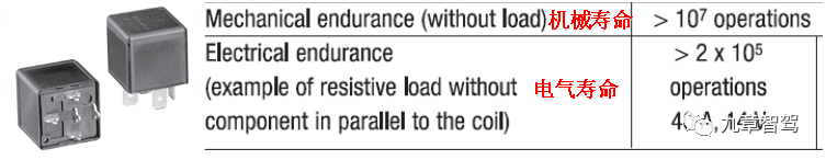
From the above figure, we can see some basic characteristics of relays:
(1) The electrical life of relays is far less than the mechanical life. In other words, when a relay breaks down, it can still move but won’t conduct electricity. You can hear it clicking, but the car won’t work.
(2) Due to the limitation of 200,000 cycles, the engine compartment relays are designed to be replaceable.
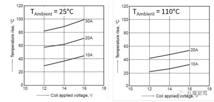
(3) The temperature of relays depends on three parts: ambient temperature, contact heating, and wire package heating.
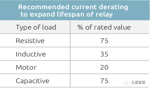
(4) Relays are derated according to the operating environment temperature.
(5) Different load conditions require different derating designs for relays.
(6) A control wire from ECU is needed, and the output wire is pulled to the electrical device, increasing the wiring loop and cost.
(7) Open-loop control cannot be monitored or diagnosed, and you may not know when it is broken.
(8) Commercial vehicles with long wiring harnesses may produce high-voltage pulses that are harmful to other electronic equipment, affecting the EMC performance of the whole vehicle. We will discuss this in the next article “What Kind of Electrical Architecture is Needed for Autonomous Commercial Vehicles.”
(9) There is a “Dry switching” problem. Poor design can affect the service life, and it is difficult to detect this design problem in the early stage. Its essence is that when the relay contacts are switched, especially when they are released, a minimum current is required to generate an arc to clean the contact surface. No arc will affect the service life, and too large an arc will also affect the service life.
(10) The design application of relays is relatively simple, and there is usually no problem based on past experience and recommendations from relay suppliers.
Basics of Semiconductor-Based Power Distribution Technology
In fact, in the control of low-current loads such as lighting loads and relay wire packages in vehicles, MOSFET-based HSD chips (High side switch) have already been widely used. However, due to the cost and technological development speed of HSD chips, traditional relays are still used for high-current load control in vehicles.
Traditional fuses and relays are both mechatronics, which belong to the field of materials and mechanical and electrical combination. MOSFET and HSD chips based on semiconductor technology are electronic devices, and there is a fundamental difference between the two. Their difference is even greater than that between Nokia’s feature phones and Apple’s smartphones, similar to the difference between plants and animals.There are two types of semiconductor-based power distribution schemes according to the application scenario:
-
Driver chip + MOSFET discrete solution. The complexity of this solution is very high, which is reflected in the following aspects: difficulty in current detection, complex circuit protection, complex diagnostic function, less protection function, slow protection speed, and complex protection strategy. The integrated cost of this solution is relatively high and it is suitable for high current occasions. At present, there are fewer car applications – car applications with high currents are still mainly based on fuses + relays.
-
HSD intelligent high side switch integrated solution, which integrates driver + MOSFET + current detection + thermal protection + voltage protection + EMC + various diagnostics on a single chip. This solution began to become popular 10 years ago and is still limited to small current load applications (<25A). It has low cost and high reliability.
Tesla’s FBCM uses a large number of MOSFETs with low RDS_ON (i.e. low conduction impedance and high current) for power distribution, with a total number of more than 50, and uses Infineon’s HSD chip for low current. As for the LBCM, which is the secondary power distribution, only about 20 MOSFETs are used. It can be seen that Tesla adopts solution 1 for high currents and solution 2 for low currents according to the situation.
Below is Infineon’s prediction of the progress of chip replacement for relays:
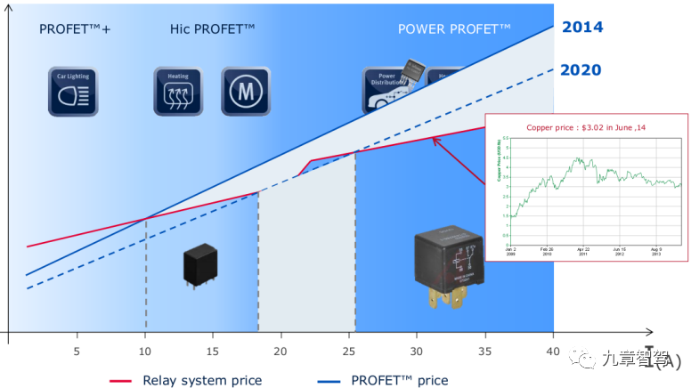
In the future, the direction will definitely be the intelligent HSD based on a single chip solution. With technological progress and cost reduction, the application range will gradually expand to the entire electrical system of the vehicle, but individual high-current applications will still adopt the driver + MOSFET discrete solution. The estimated time for the full vehicle electrification is between 2025 and 2030.
Currently, there are several major suppliers of intelligent HSD chips:
-
Infineon, which originated from Siemens’ semiconductor division. Infineon has the most comprehensive models, the largest series, and the widest application range. From the classic series to the 5th and 7th series, it covers 12V passenger cars and 24V commercial vehicle applications. Infineon’s HSD chips are the most widely used in the market.
-
STMicroelectronics, also a veteran car chip manufacturer, has the most complete models and the largest series besides Infineon, covering passenger cars and commercial vehicles from the 5th to the 7th series. It is the second in the market ranking.3. NXP NXP Semiconductors is an established manufacturer of automotive chips, and its HSD product line originated from the former Freescale, which can be traced back to Motorola. With strong technical strength and unique chip design, many of their general products originate from customized products, which may have different names, but are widely used in reality. The product series covers both passenger cars and commercial vehicles.
-
TI Texas Instruments is a global giant in analog components, and you can hardly avoid their products in the fields of consumer electronics, industrial, and automotive. As for HSD, a chip with huge demand, how can TI stay out of it? Thus, they have been gradually releasing their HSD products since 2014, and the chip series has been improving, but still limited to 12V passenger cars (commercial vehicle volume is still too small).
-
Onsemi On Semiconductor was spun off from Motorola’s semiconductor division in 1999. In 2016, Onsemi acquired Fairchild Semiconductor, founded by the eight genius scientists who also proposed “Moore’s Law”, followed by Intel, AMD and Silicon Valley. Without going too far off topic, Onsemi has fewer HSD models, and mainly focuses on small current applications, serving as a design supplement.
By now, have you noticed that they are all European and American companies, and not even Japan, a major player in automotive chips, has one? This is because HSD is based on automotive-grade MOSFET, and Infineon and ST have a good foundation in automotive-grade MOSFET. HSD technology combines digital and analog technologies, which requires high chip-making process and reliable performance in harsh automotive environments. Thus, unlike other types of chips, there are few manufacturers worldwide who can make HSD chips.
Moreover, as the volume of commercial vehicles is small, less than half of passenger cars, and China accounting for about one-fourth of it, except Infineon, ST and NXP, no other company has ventured into this field, and even these few companies have no recent plans for new products.
Changes brought by semiconductor-based power distribution technology
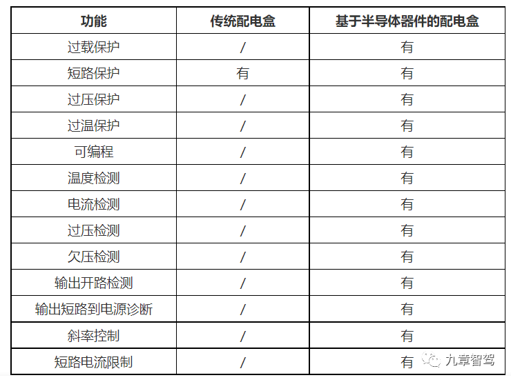
- More Functional
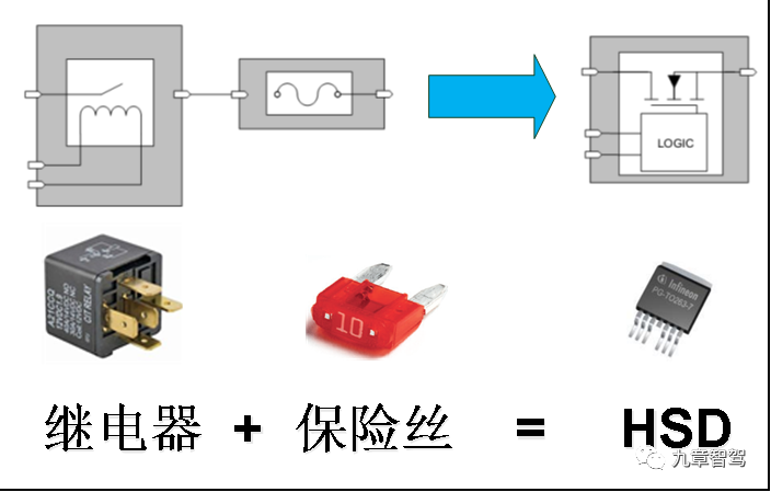
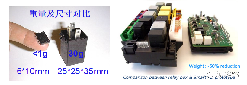
A single HSD chip can replace one fuse and one relay, while achieving controllable switches, circuit protection and diagnostic functions. Besides, it has more functions, smarter, more reliable, smaller, and lighter.
The following table shows the specific function comparison:
Stronger Safety and Diagnostics
Strong protection and diagnostic capabilities are the foundation of reliability and intelligence. Through the comparison of basic functions, have you found that smart semiconductor-based power distribution boxes and traditional power distribution boxes are not the same species at all? Although they are both called power distribution boxes, their nature is completely different. Their differences are probably larger than the functional differences between Nokia’s feature phones and Apple’s smartphones.
Performance
After talking about the functions, let’s look at performance. Without further ado, let’s take a look at the comparison table below.
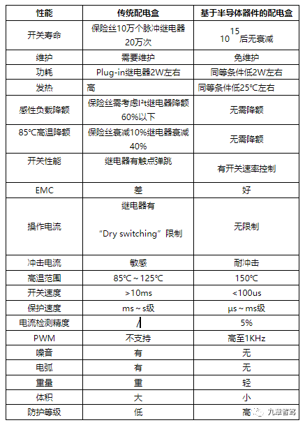
From the performance comparison, we can see that in terms of lifespan, difficulty of use, temperature range, application range, switch speed, protection speed, etc., the performance of smart semiconductor-based power distribution boxes completely surpasses that of traditional power distribution boxes. This is the electronic technology surpassing traditional electromechanical technology, and it is the smart networked era surpassing the industrial era.
EMC Performance
We mentioned EMC in the performance comparison above, and we still want to talk about it separately here. I guess many of you are concerned about this.
For passenger cars, the trend of electrification is very strong. Those who make electric cars know that the high-voltage system after electrification will bring many vehicle-wide EMC problems. Compared with this, EMC of the power distribution box may be a small problem, but we will solve it if we can.
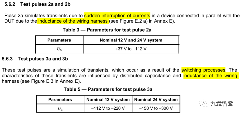
The main EMC problem of traditional power distribution boxes is caused by the instantaneous fuse protection and relay bounce during operation. This is produced by the wire harness inductance, and ISO7637-2 has special test requirements for this. The highest voltage of the 12V system can reach 220V.
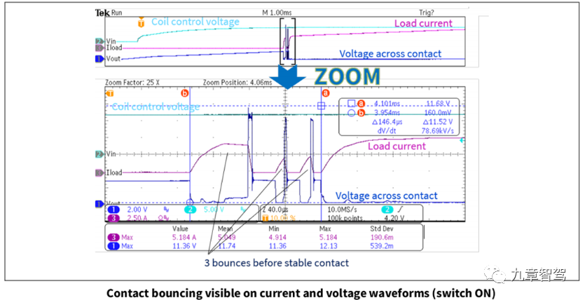
Let’s take a look at the bounce of the relay when it is energized. Many small partners who are not familiar with the characteristics of the relay may think that the relay just snaps into place with a “click.” If you think so, you’re wrong, and even Isaac Newton’s coffin can’t hold this idea down. As long as an object moves, you have to follow Newton’s law, right? As an elastic body, the relay contact is bound to rebound after being snapped into place. It can’t stop suddenly. From the waveform below, we can see that it rebounded several times before stopping. This type of rapid switching will cause significant EMC interference to the system through the wire harness.
 Since the wiring harness of commercial vehicles is generally longer, the impact is even greater. In addition, there are other issues with commercial vehicles, which will be discussed in detail in the next article, “What Kind of Electrical Architecture Does Autonomous Commercial Vehicles Need?”
- Higher Reliability
Regarding reliability, please refer to the article “Get Rid of Fuses and Relays for Safer Autonomous Driving”, and I won’t go into details here.
As for the reliability of dual power supply, including dual power input and dual power output, this is a concern for many people, so let me explain further.
The difference between traditional power distribution boxes and Tesla’s is as follows:
(1) For single-circuit open circuit faults, they are basically equivalent. If either power supply fails, it will not affect the power supply.
(2) For single-circuit short-circuit faults:
① The traditional design is a power distribution box with two parallel input sources. The power input has only one terminal block, and a short circuit may cause a power failure; while Tesla uses two power source terminal blocks, which is obviously more reliable.
② Even if two lines enter the traditional power supply box and are equipped with double insurance, due to the protection speed issue of the insurance, the power supply may be lowered to under-voltage instantaneously, causing a power failure. Most Tier 1 autonomous driving systems require rapid shutdown of power surge branches, with an isolation time of about 100µs, which obviously cannot be achieved by fuses. The protection action speed of semiconductors can reach the level of 10µs.
③ Tesla uses dual-power parallel design after isolation by MOSFET, which can achieve fault isolation. For single-circuit short circuit faults in the output, Tesla’s solution can achieve shorter isolation time.
In the new electronic and electrical architecture of the Model 3, the power distribution architecture and load control are all based on semiconductor devices, and the power distribution architecture fully considers the requirement of power redundancy for the power supply and control functions of highly autonomous driving assistance systems. For example, the power input redundancy is achieved by the 12V battery power supply (BATT+) and the 12V power supply output (DC/DC IN) of the high-voltage DC/DC module. EPS1 and EPS2 also have redundancy for EPS outputs.
- Programmable
As mentioned in the analysis of Tesla’s architecture, HSD realizes the fusion of protection and control. Protection is control, and control is protection, which will bring two major advantages:
① The power distribution box will no longer be a power distribution box. Most of the distribution functions have now been upgraded to controllable functions. That is to say, the power distribution box can be used as a controller, and distribution and control are also integrated.②Each circuit is independently controllable, which means that each line supports individual programming control. This is extremely significant, as it represents the “decoupling of software and hardware,” and when combined with OTA, it forms the foundation for SDV. Tesla has already built this foundation with the Model 3.
- Long lifespan, maintenance-free
We discussed reliability in our previous article regarding long lifespan, so we won’t go into detail here. Because of the characteristics of semiconductor components, all three BCMs from Tesla are fully sealed and cannot be opened without specialized tools. This means that non-professionals cannot perform maintenance, and even if they opened it, they wouldn’t be able to understand it or fix it.
Because electric cars, unlike fuel cars, do not require oil or filter changes, the maintenance period is already longer. Now, even the insurance box is maintenance-free, so Tesla doesn’t even need a 4S store.
Another benefit of maintenance-free is that the power distribution box does not require an “easily accessible design,” which is more friendly to the overall vehicle design. From another perspective, the overall vehicle design is simpler, the layout is more flexible, the efficiency is higher, the speed is faster, and the cost is lower.
You see, this is very “Muskian,” revealing “efficiency” and “cost” in every aspect. For those who have not worked in a car factory, as a layout engineer, they are either “quarreling” with other departments every day, or on their way to “quarrel.” With fewer design limitations, they have fewer hairs to lose.
- Improved protection level for increased safety
As mentioned earlier, maintenance-free brings another benefit: the design of the power distribution box can achieve full-sealing design, resulting in an improved protection level. For example, the original power distribution box was just a plastic box with a plastic cover and a few buckles. The protection level was only up to IP54. Now, with full-sealing, it can reach IP67 or IP69, which means that even if the engine compartment is flooded, the entire vehicle power supply can still be guaranteed, which is particularly important for electric cars. For users, the power distribution box will not break after being in contact with water, which reduces maintenance costs.
- Energy-saving, miniaturization, and lightweight
In the performance comparison, we mentioned energy consumption, weight and volume, but did not give specific comparisons. Here, we will explain in detail.
Let’s first look at the power consumption comparison at the device level. It can be seen that under the same conditions, the power consumption of a single intelligent switch can be reduced by about 2W. For a car with ten of these, power consumption is reduced by around 20W.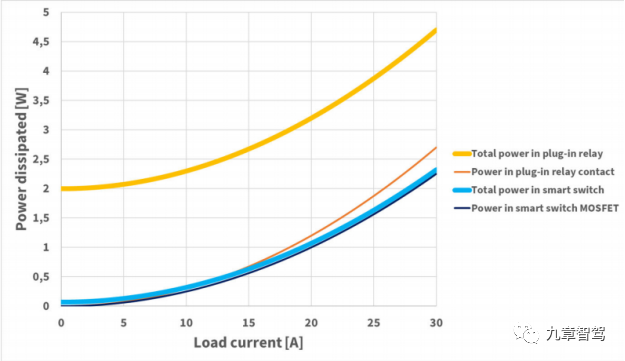
First, let’s take a look at the comparison of device-level size and weight. The miniaturization and lightweighting of device-level is the foundation of miniaturization and lightweighting of distribution box. As far as I know, for the same function, the volume of smart distribution box can be reduced to about 1/2 of the traditional distribution box, and the weight can be reduced to about 1/3. I don’t know if you have ever felt the weight of a traditional distribution box, which is generally six or seven catties and very heavy to pick up. Even if it is a metal shell (traditionally plastic shell), it will be much lighter after digitization.
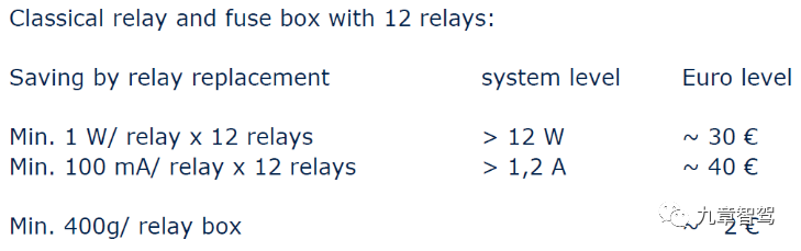
Nowadays, everyone is talking about energy conservation, emission reduction, carbon neutrality and lightweight design. Intelligent distribution box based on electronics has a huge advantage in this aspect. The following is the system-level cost savings calculated by Infineon based on the EU carbon emission standards.
- Diagnostic and networkable
Another advantage of electronic electrical components is that they can be monitored, diagnosed and controlled in a closed loop. It used to be a black box, but now it has become transparent, just like you suddenly being able to perceive your heartbeat and blood pressure, and the vegetative nervous system is connected to the brain nerves. Isn’t it exciting to think about it? What’s the use of smart watches and blood pressure monitors then?
The significance of diagnosis is huge. The current and voltage of each circuit of the whole vehicle can be monitored at any time. The current detection accuracy of HSD can be up to 5% or even higher. The working status of the load is clear at a glance. With big data and AI, is not it exciting to think about the endless possibilities of the future? Whether you want to do whole-vehicle energy management, or voltage balancing, or fault diagnosis or warning, it’s up to you, and your territory listens to you.
Of course, information security after networking is a must, otherwise it will be troublesome if it is controlled by hackers. In this way, traditional technology security is still important!
- Accurate power supply management
After each circuit is individually controllable, you can do accurate power supply management, which is much more advanced than traditional distribution boxes that only have a few ACC, IGN1, IGN2, START. You can decide how to play, such as automatically cutting off power to which loads in case of insufficient power, or remotely controlling which functions after parking. Your territory listens to you.As we mentioned earlier, traditional OEMs have a heavy historical burden. Based on experience, sharing modules and platforms can significantly reduce vehicle costs and ensure vehicle reliability, but it also leads to the difficulty of making any changes, a long cycle and a high cost, because any small change can have a huge impact. Some functions may require a paid subscription, which also brings to mind Tesla’s “hardware reserved + software subscription” model. As an OEM, have you discovered some business opportunities?
Of course, everything has its price. Traditional cars have extremely strict static current requirements. The static current of the whole vehicle is around 15mA after being de-energized. After parking, the high voltage of new energy vehicles is de-energized (the high voltage is cut off after turning off), but Tesla says that it wants to take an unconventional approach and not de-energize the high voltage after parking. Tesla’s BMS has a special design that can take electricity from the high-voltage battery and convert it into low-voltage 12V for the whole vehicle to use, which ensures that the battery does not lose power.
The price Tesla paid for this is that even if the car is stationary, the high-voltage battery still loses about 1% of its charge per day. You may ask, won’t it drain the high-voltage battery? Indeed, Tesla has made corresponding strategies. Some functions will be disabled when the battery level drops below 20%. Therefore, Tesla is daring and careful at the same time.
- Controllable Power Supply Timing
The power supply timing of traditional distribution boxes is basically fixed, and once designed, it is difficult to change later. But when each road becomes individually controllable, the power supply timing and power-off timing can be fully controlled, and programming and OTA are possible.
- Fast Iteration Speed and Low Design Change Cost
Based on the analysis above, we can see that the functions of traditional distribution boxes are fixed and cannot be upgraded. When designing, it is necessary to check the margin of the wiring harness, which makes the design verification complicated, the calculation is complex, and the test cycle is long, and the update iteration speed is slow. To ensure compatibility with different vehicle models and configurations, a large amount of space needs to be reserved (a large number of empty fuse and relay position reserves can be seen from the distribution box’s picture), which increases the design complexity, raises the design cost, and reduces the flexibility and adaptability of use.
Do small partners who engage in automotive electronic design also feel this way? Nowadays, the technology iteration speed is too fast. Mobile phones are replaced every year, and the computing power of autonomous driving chips is rapidly improving. However, the development speed of automotive electronic modules still takes more than a year. Once developed, they can be used for seven or eight years without much change in the middle.As a pure mechanical and electrical device, the traditional distribution box has no software, so there is hardly any iteration. Whenever there is a change in demand, the design needs to be modified, which leads to the need for design verification time and additional costs. However, after the electrification of the distribution box, these problems disappear. The powerful hardware can achieve hardware and software decoupling, and with OTA support, it can enable the “SDV software-defined car” at low cost and fast iteration.
- Reduced overall wire harness length and weight
According to Tesla, the Model 3 achieved a halving of the wire harness length compared to the Model S, which has an internal wire harness length of up to 3 km, while the Model 3 has only 1.5 km. This significant progress is due to the innovative power of the new electronic electrical architecture, in which the innovative area architecture and electronic power distribution architecture also play a significant role. It is said that the length of the wire harness for the Model Y must be controlled to 100 m, but this has not been confirmed yet.
Let’s talk about wire harnesses in vehicles. People who work on automotive electronics and autonomous driving are probably not very familiar with them.
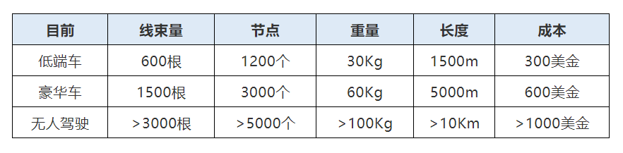
With the development of vehicle electrification, intelligence, and autonomous driving technology, the number of sensors, actuators, and various ECUs in the vehicle has exploded. Everything needs power, which requires power allocation, just like people need to eat and breathe. Where does the power come from and how does the signal transmit? This cannot be done without wires. Therefore, the length, weight, and cost of wire harnesses on cars are constantly increasing, and the complexity and cost of wire harnesses are also increasing, which in turn makes it impossible for distributed ECU architecture to support future requirements for unmanned driving, which is another topic.
Let’s first look at passenger cars, and analyze commercial vehicles separately.
Why can the power distribution architecture reduce the length of the wire harness? Let’s take a look at the architecture of the two to understand. Without further ado, here is the image.
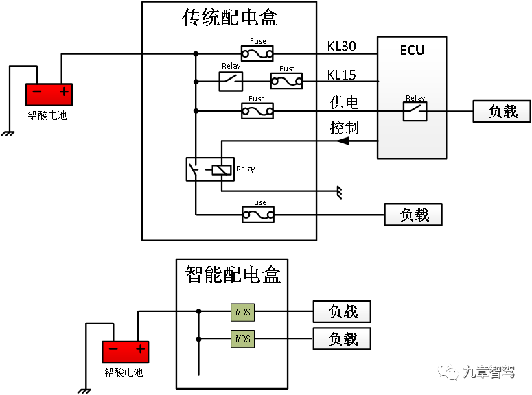
After electrification, the intelligent distribution box has been optimized to a great extent in terms of design. Power distribution is integrated with control, the distribution box has become an ECU, and signals such as ACC and KL15 can also be eliminated. The load to the battery is controlled by a single semiconductor device, and the wire harness loop is greatly simplified. The distribution box relay control circuit and the ECU relay fuse circuit are also eliminated.Let’s take a look at the wire harness weight. The length saved by circuit optimization will reduce the weight of the wire harness. On the other hand, the reduction of wire diameter brought by the intelligent power distribution box is also indispensable. As mentioned when discussing fuse and semiconductor device performance, the fuse has a large margin due to its imprecise protection, while semiconductor devices can accurately identify overloaded and short-circuit faults, achieve reliable protection, and reduce the requirements for wire diameter margin.
Without further ado, let’s take a look at the comparison table and first look at the design matching of the fuse:

Now let’s take a look at the design matching using semiconductor technology:
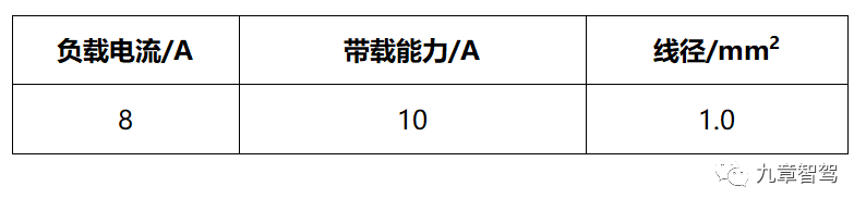
From the above comparison table, we can see that with the same load current, the wire diameter can be lowered by one notch. If the load is a motor type load, it can be lowered by two or more notches.
- Cost reduction of 5%-20%
We have already discussed lightweight and miniaturization, as well as the reduction of wire harness costs brought about by saving wire harness circuits and reducing wire diameter. We have also discussed the cost comparison between relays and HSD chips. A few sentences are not enough to explain the cost issue, so we will analyze it in several parts:
-
Distribution box BOM cost: Undoubtedly, the cost of electronic intelligent distribution boxes will be much higher than that of traditional distribution boxes for a long time to come.
-
Wire harness cost: According to the author’s understanding and calculation, the cost of the entire vehicle wire harness can be reduced by about 20%. For commercial vehicles with larger design margins and more wire harnesses, the reduction is even greater, which we will discuss in another article.
-
Cost savings from vehicle production and assembly efficiency: This part is difficult to evaluate, but the cost does decrease.
-
System cost: With an increase in BOM cost and a decrease in wire harness cost, the system cost can be reduced by about 5% to 20%, depending on the vehicle model and architecture.
-
Later-stage costs, including the reduction in workload brought by compatibility and iterability, cost reduction, and the reduction of after-sales maintenance costs, cannot be effectively quantified but are worth considering.
Connected vehicles and big data applications
Finally, let’s also touch on hot topics and discuss what applications and values the electronicization of distribution system architecture can bring, which is like casting a brick to attract jade. Let’s brainstorm together, guys!
- Digitalization of energy managementThe original energy management of the whole vehicle was quite crude because it was estimated without accurate measurements, inability to measure and without networking. However, with digitalization and networking, we can now increase the granularity, quantity and real-time nature of data. This is where big data and AI come into play. It’s similar to the widespread use of smart electric and water meters, where police can use big data analysis to catch drug dealers by identifying abnormalities in electricity and water usage, while community services can quickly identify risks of elderly people falling by detecting unusual water usage.
After digitalization and networking, OEMs can obtain the current of every load and module as well as the overall current of the vehicle in real-time through the backend, gaining access to the vehicle’s load profile data. It can be analyzed according to the following dimensions:
-
Analyze vehicle load profile data by time of day on a daily basis and analyze difference between daytime and nighttime data.
-
Analyze vehicle load profile data on a seasonal basis, identify seasonal differences, and obtain relevant data on how environmental temperature affects the vehicle.
-
Distinguish seasons based on the windshield wiper and lighting data, analyze the combined effects of rain and temperature, and at night on the vehicle’s load profile data. Obtain information on the vehicle’s maximum load profile data under extreme conditions.
-
Analyze data under running and non-running vehicle speeds and ON/ACC signals, guide selection of generator, DC-DC, and battery parameters as well as incorporate sleep mode into vehicle design.
-
Compare and analyze load profile data of the same vehicle in different years over the course of a year, and obtain relevant data on seasonal impact on the vehicle.
-
Analyze load profile data of vehicles of the same type and identify differences. Create a load profile database to detect vehicle anomalies in advance, reduce maintenance costs, and provide guidance for reasonable vehicle use for drivers, thus reducing operating costs.
-
Analyze the maximum load profile and, using software strategies or driving guidance, reduce the maximum impact current of the vehicle, increase safety, reduce vehicle design margin, reduce vehicle costs, and guide software strategy design.
-
Maintenance Reminder
Based on big data, every load on the vehicle can be profiled, and combining it with historical data and load characteristics, the lifetime of components can be analyzed and risk can be forecasted. For example, the life of a halogen headlight bulb might be 500 to 600 hours. This can be used to remind the user to replace the bulb ahead of time, avoiding having to replace it later once the bulb has burnt out. It’s just like iwatch which monitors our daily activity, sleep and calorie data, and provides timely reminders to correct our lifestyle habits or undergo physical examinations to maintain good health.
- Fault Prediction
Based on big data analysis of users’ driving habits, abnormal situations can be detected in time and fault warnings can be given. For example, even if certain circuit currents are within normal range, if they are detected to be abnormal through big data analysis, users can be reminded to check and avoid potential driving risks through dashboard or app.
- Lower Operating Costs for Commercial Vehicles
For commercial vehicles, frequent repairs are needed due to their usage characteristics. Each breakdown implies an increase in operating costs. Therefore, by combining maintenance data, a digital maintenance workshop can be established for each vehicle, providing data support for vehicle maintenance, warning in advance and preventing breakdowns during operation, thereby reducing operating costs.
Through the above analysis, have you discovered some opportunities for “software payment” again? Do you have a new understanding of Tesla’s “hardware pre-threading + software payment” model?
For a long time, we have only focused on hardware BOM costs and not much on iteration costs, vehicle manufacturing costs, user maintenance costs, and the “software value of hardware”. Has Musk dealt us a “diminished strike” in this regard? Musk’s “first principle” actually stands on a higher level to think about global problems and propose solutions. This is worth pondering.
When we come to this point, have you noticed that this is related to the model of “Scenario-Data-Algorithm” in the autonomous driving industry? After upgrading the traditional distribution box to a smart one, digitalization and data were introduced. However, having data alone is not enough without sufficient granularity. After the digitalization and granularity are refined, multi-dimensional data can be combined with usage scenarios. With the rapid iteration of algorithms, data + algorithm + scenario can work together and create value.
Returning to the title, why does Tesla want to get rid of fuses and relays? I believe that every buddy has their own answer by now. Many times we only see the results, not the reasons, but this result points the way to the future.
Due to the length limit, we will conduct a deep analysis on the electrical architecture of autonomous driving commercial vehicles in the next article. Stay tuned!
This article is a translation by ChatGPT of a Chinese report from 42HOW. If you have any questions about it, please email bd@42how.com.