Over the weekend, I engaged in one-on-one communication and had discussions on technology issues with friends to review the technical development of OBC and DCDC for the next step. There was a general consensus in this field.
When it comes to the inverter and three-electricity domain controller for the next step, and the power distribution architecture, I would like to delve into the emergency power supply solution developed by Power Integrations for specific details.
Power Integrations’ InnoSwitch™3-AQ
In this regard, Power Integrations mainly tackles the issue of controlling the low-voltage power supply for the inverter. In traditional designs, the 12V conventional low-voltage power supply architecture is used, and the low-voltage input path must provide redundancy to meet ASIL requirements. This is mainly due to compliance considerations. In the absence of 12V power input conditions, the charge on the bus capacitor cannot be released actively.
Note: Companies typically address design concerns through an additional discharge resistor.
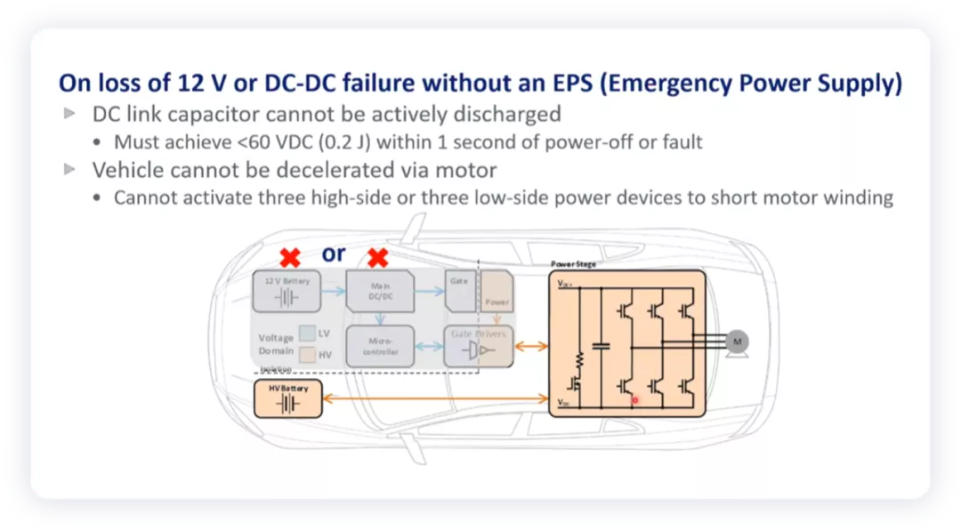
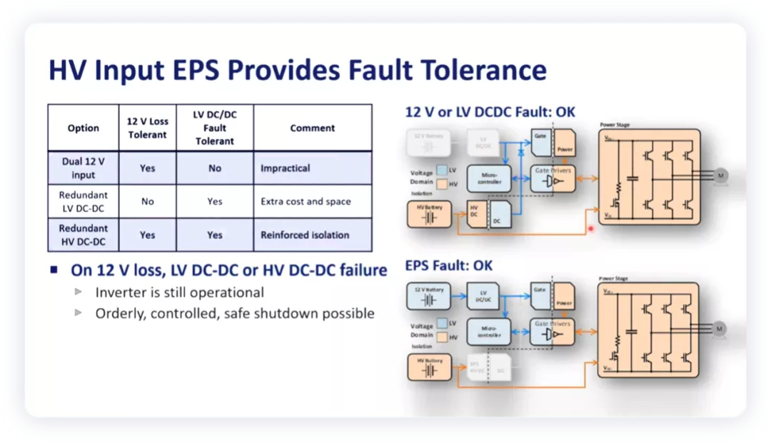
So, from the perspective of Power Integrations’ considerations, the inverter needs to work under both 12V low-voltage and high-voltage power supplies (supporting 400V and 800V systems) to allow safety functions to work without voltage, enabling the MCU to perform safety releases.
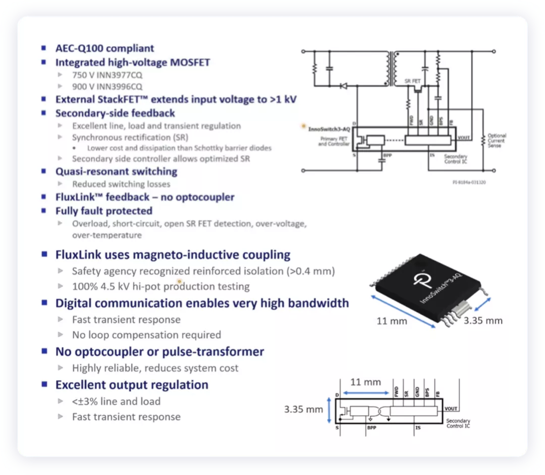
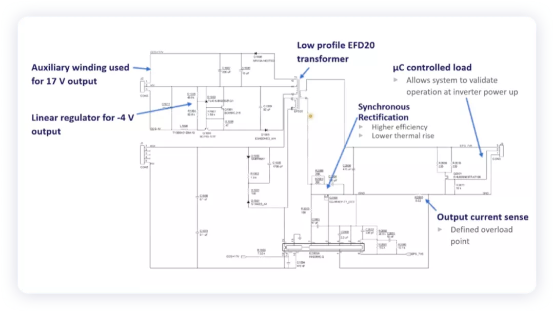
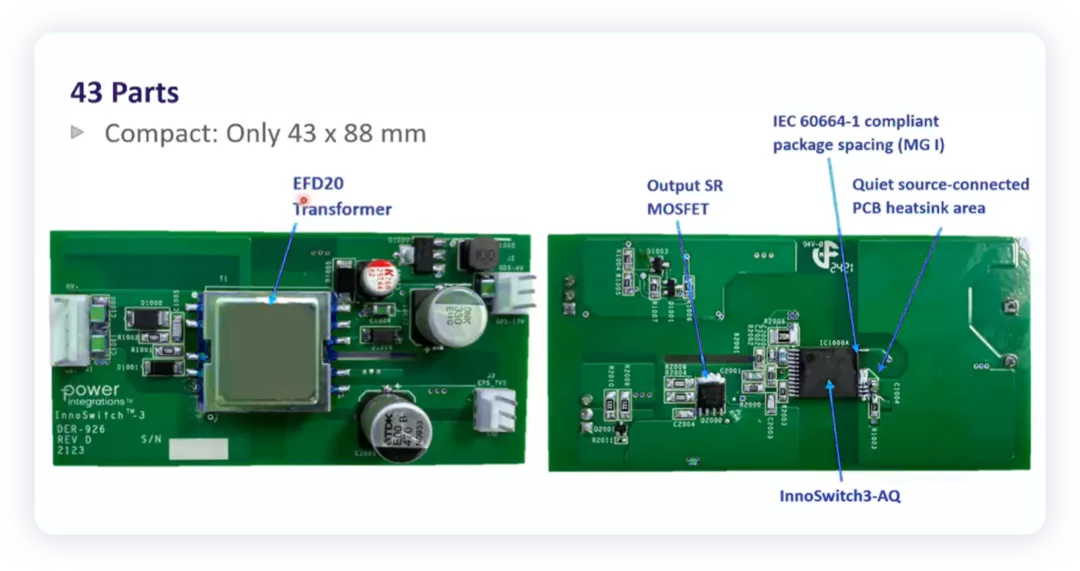
Power Integrations’ specific solution is to design an InnoSwitch™3-AQ flyback switch, which is certified by AECQ for automobiles. This module combines primary and secondary controllers and safety feedback circuits into a single IC.
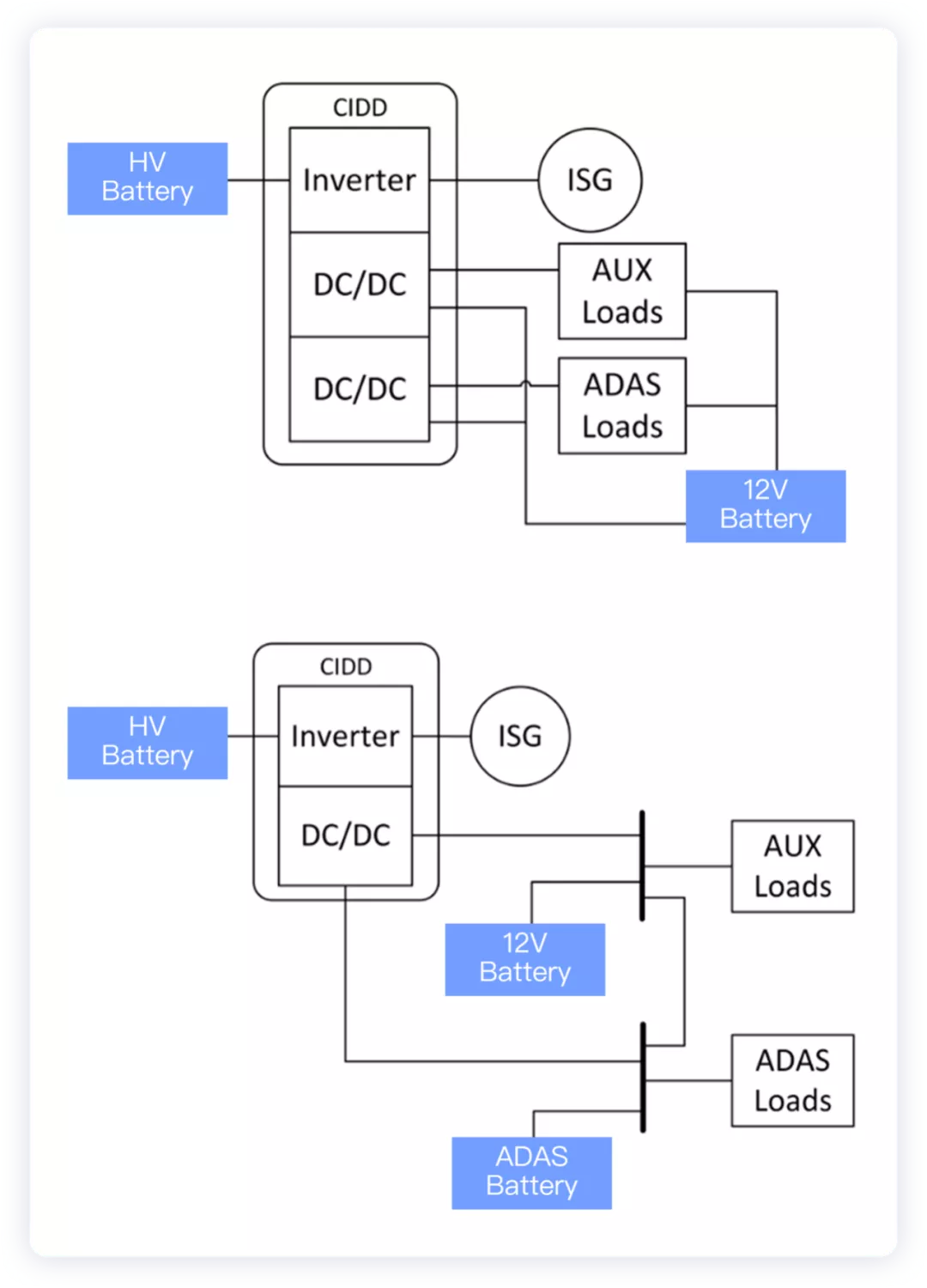
From a high-level perspective, the functions of the vehicle are divided into different safety levels, which require the configuration of redundancy for different safety needs. For example, a separate 12V power supply system is configured for some important units, such as the future core actuators (brakes and steering), with a design of two batteries, two DCDC converters, and distribution lines.


Of course, such configuration may not be reasonable. From the perspective of centralized architecture, it is possible to directly divide them into two types: dual DCDC single battery + dual battery or single DC-DC different modes.
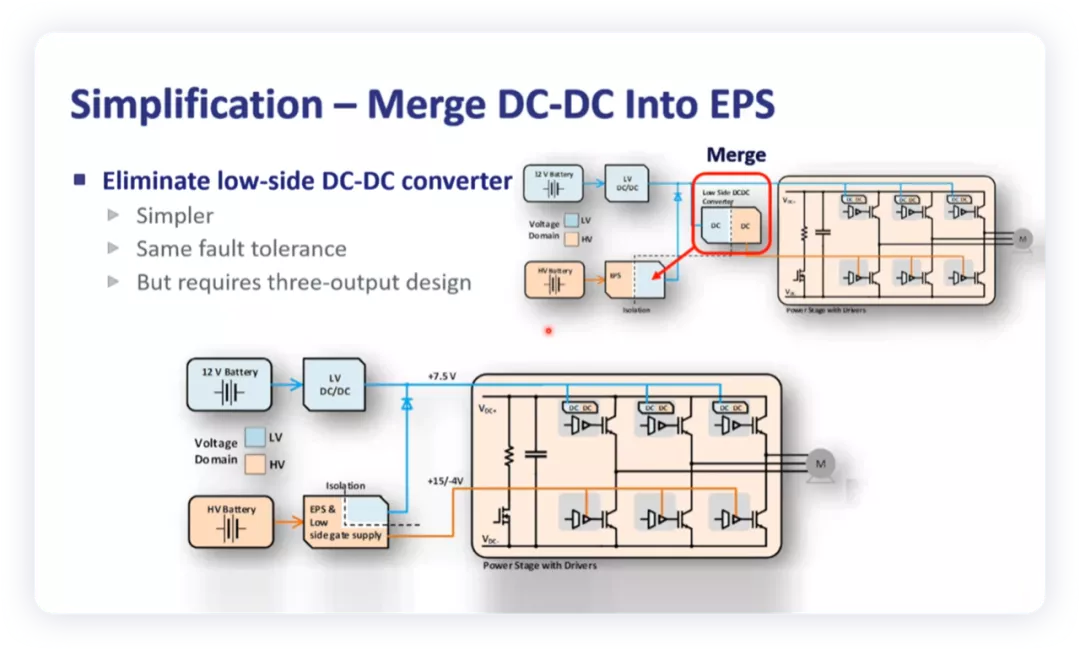
Moreover, if we expand our imagination, we can directly configure an independent computing power supply path based on high-level integration to provide high-voltage power supply paths for the computing platform, making the DCDC module similar to PI’s vision, which may be a more direct way.
One interesting example I have heard before is to use two high-voltage batteries of different sizes to completely replace the original 12V battery, realizing the concept of never power-off in the power supply system. In fact, the preparation of two high-voltage configuration inputs ensures that low voltage is never lacking, so the high-voltage DCDC module can be distributed, which is another solution.## Summary:
In my personal opinion, all supercomputing platforms are equipped with power architectures that match high computing power, and it may be more reasonable to directly use a DCDC (400/800 -48/12V) power supply design for future supercomputing platforms if high voltage is provided locally.
It may not be reasonable to supply power with 12V overall because the path is too long.
This article is a translation by ChatGPT of a Chinese report from 42HOW. If you have any questions about it, please email bd@42how.com.