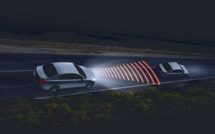
In the previous sharing post, I introduced the principle, data, and functions of the LiDAR on autonomous vehicles.
The biggest challenge for the popularization of LiDAR is the high cost. The price of a single LiDAR may exceed that of an ordinary car, so there is currently no possibility of large-scale production.
In order to promote the development of autonomous driving technology and solve the problem of inaccurate ranging and speed measurement of cameras, engineers have chosen the cost-effective millimeter wave radar as the sensor for ranging and speed measurement.
The millimeter wave radar not only has the advantage of moderate cost but also can handle sand and dust weather that LiDAR cannot handle.
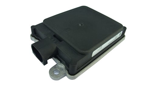
The following picture shows the millimeter wave radar used in Baidu Apollo 2.0 – Continental’s ARS-408, which is installed in the middle of the car bumper and faces the direction of the car.
Classification of millimeter wave radar
Electromagnetic waves with frequencies between 10 GHz and 200 GHz are called millimeter waves because their wavelengths are in the millimeter range. The millimeter wave radar applied in the field of autonomous driving mainly has three frequency bands: 24 GHz, 77 GHz, and 79 GHz. Millimeter wave radar with different frequency bands has different performance and cost.
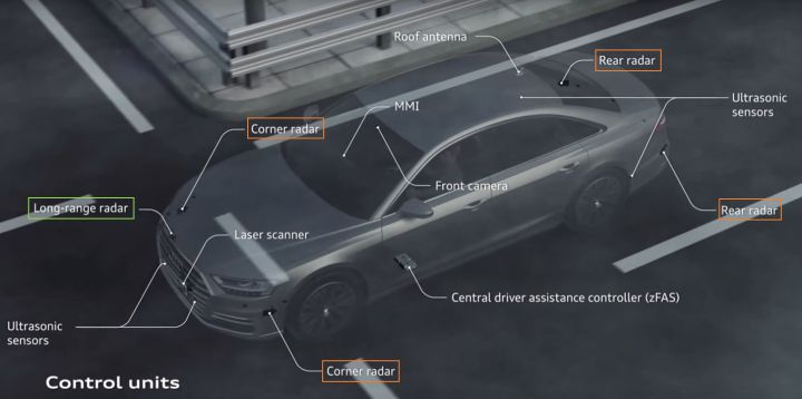
Taking the sensor layout of Audi A8 as an example, let us explain the functions of millimeter wave radar in different frequency bands.
Short-range radar: 24 GHz band
The radars marked with orange boxes in the above picture, Corner radar and Rear radar, are radars in the frequency band around 24 GHz.
The detection distance of the radar in this frequency band is limited, so it is often used to detect nearby obstacles (vehicles). These four corner radars can achieve ADAS functions such as blind-spot detection and lane-changing assistance; in autonomous driving systems, they are often used to perceive obstacles near the vehicle and provide perception information for lane-changing decisions.
Long-range radar: 77 GHz bandThe Long-range radar marked in the green box in the image above is a radar with a frequency band around 77 GHz. The maximum detection distance of a high-performance 77 GHz radar can reach more than 160 meters, so it is often installed on the front bumper facing the direction of travel. The brown area in the lower right corner of the following image is a long-range millimeter wave radar equipped in Tesla AutoPilot 2.0 and its perception range.
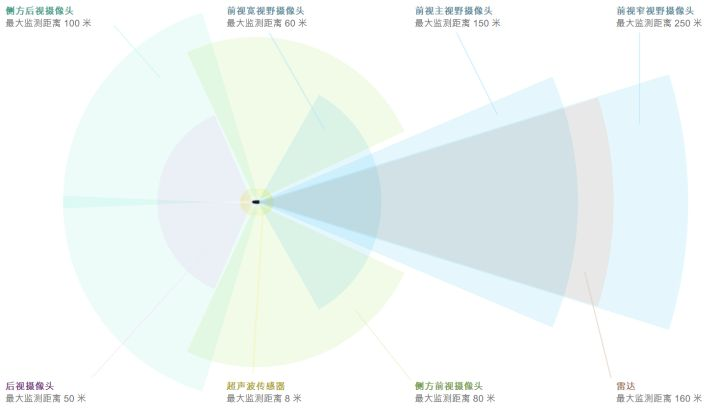
Long-range radar can be used for ADAS functions such as emergency braking and highway following. It can also meet the measurement requirements of obstacle distance, speed, and angle in the field of autonomous driving.
Long-range radar: 79 GHz frequency band
The functions that sensors in this frequency band can achieve are the same as those of 77 GHz and are also used for long-range measurement.
According to the formula: speed of light = wavelength x frequency, the higher the frequency of the millimeter wave radar, the shorter the wavelength. The shorter the wavelength, the higher the resolution, and the higher the resolution, the higher the measurement accuracy of distance, speed, and angle. Therefore, 79 GHz millimeter-wave radar is undoubtedly the trend of future development.
Compared with laser, millimeter-wave radar has stronger penetration and can easily penetrate the plastic on the bumper, so it is often installed inside the car bumper. This is also why it is difficult to find millimeter-wave radar on many cars that have ACC (adaptive cruise control) from their appearance, even if they actually have one.
Data of millimeter-wave radar
Since the ranging and velocity measurement principles of millimeter-wave are both based on the Doppler effect, the original data of millimeter-wave radar is based on a polar coordinate system of (distance + angle), which is different from the Cartesian (XYZ) coordinate system of lasers. Of course, the two coordinate systems can be converted to each other according to trigonometric functions.
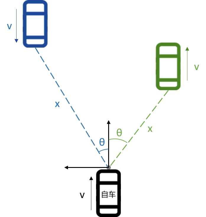
As shown in the figure below, there is a blue car coming towards the front of the ego car and a green car driving in the same direction which are detected by the millimeter-wave radar.
The electromagnetic waves emitted by the millimeter-wave radar can penetrate the front and rear bumpers of the car, but cannot penetrate the metal of the car chassis. Therefore, when encountering objects that millimeter-wave radar cannot penetrate, such as metal, the electromagnetic waves will return.
Taking Delphi’s forward millimeter-wave radar ESR as an example, the radar can return data of up to 64 targets per frame, and the data of each target is composed of:
-
powerEcho intensity, measured in decibels. The echo intensity of different types of obstacles (cars, metal guardrails, motorcycles, etc.) at different distances may also vary. If the echo intensity is too low, the signal can be identified as noise.
-
trackbridgeobjectType
Whether the detected obstacle is a bridge. In urban roads, there will be scenes where overpasses are encountered. The signal obtained from the ESR can be used to determine whether the detected obstacle is a bridge.
- track_oncoming
Whether the obstacle is approaching. This flag is mostly used in AEB (Automatic Emergency Braking) in active safety.
- track_id
The “ID card” of the obstacle. Each obstacle will have a fixed ID, and the ID range is 0-63.
- track_status
The tracking status of the obstacle.
- track_theta
The angle between the obstacle and the millimeter wave radar. The θ angle in the illustration is the value here. Due to the limit of each radar’s detection range, for example, the θ range in the ESR is between 45° and 45°.
- track_distance
The distance between the obstacle and the millimeter wave radar. This distance is the distance in polar coordinates, that is, x in the illustration. The Cartesian (XYZ) coordinates of the vehicle can be calculated based on x and θ.
- trackrelativeradial_velocity
The radial relative velocity between the obstacle and the vehicle. Due to the principle of Doppler effect, the radar measurement can only provide radial velocity in polar coordinates, and the measurement confidence of tangential velocity is very low, so the radar does not provide the tangential velocity of the obstacle.
- trackrelativeradial_acceleration
The radial relative acceleration between the obstacle and the vehicle. This value is obtained by differentiating the radial relative velocity.
- trackmodetype
The motion state of the obstacle. Based on this value, it can be determined whether the obstacle is stationary or moving.
- track_width
The width of the obstacle. After clustering the original radar data points, an area will be obtained, and the range of this area is regarded as the width of the obstacle.
Currently, the four mainstream millimeter wave radar suppliers in the world are Autoliv, Bosch, Continental, and Delphi, referred to as ABCD in the industry. The functions provided by the millimeter wave radar products of these companies are similar, and most of the functions are calculated based on the echo energy, distance, and angle information of the obstacle.
Challenges of millimeter wave radar
Before discussing the challenges, let’s first intuitively feel the lidar data. This video shows millimeter wave radar data collected on a certain highway.Translate the Chinese Markdown text below into English Markdown text. Preserve the HTML tags inside the Markdown and only output the results.
The left image shows the position information of obstacles detected by a millimeter-wave radar, while the right image depicts an actual road scene.
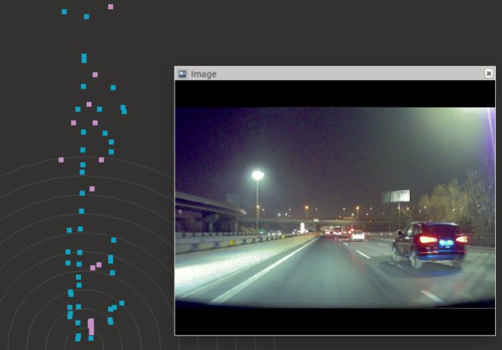
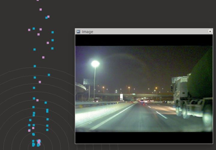
The center of the gray circle in the figure is the installation position of the radar. The blue dots are stationary obstacles, and the pink dots indicate moving obstacles.
We can clearly see that the blue dots form a straight line, which is actually a railing. But how can we make the computer know that there is a railing among so many dots? That’s what algorithm engineers need to do every day.
In the actual development process, applying millimeter-wave radar in the field of autonomous driving faces the following three challenges.
Challenge 1: Poor data stability
Obviously… when seeing such messy and unstable data, engineers also feel desperate. The data instability poses high demands on subsequent software algorithms.
Challenge 2: Sensitivity to metals
Due to the extreme sensitivity of electromagnetic waves emitted by millimeter-wave radars to metals, during actual testing, nails suddenly appearing on the road surface or metal billboards far away will all be regarded as obstacles. Once the vehicle is traveling at high speeds and is disturbed by these suddenly appearing obstacles, it will lead to continuous braking, resulting in a decrease in the comfort of the car.
Challenge 3: Lack of height information
The data provided by millimeter-wave radar can only provide distance and angle information, and cannot provide height information like laser radar. The obstacles without height information will bring many challenges to technical development.
Summary
The above sharing basically helps everyone understand the principles of millimeter-wave radar and what the data looks like. Combined with the characteristics of laser radar and camera introduced in the previous articles, it can be found that different sensors have their own advantages and disadvantages. The main focus of my current work is how to integrate the strengths and make up for the weaknesses of these sensors.
Well, that’s all for this sharing about millimeter-wave radar.
This article is a translation by ChatGPT of a Chinese report from 42HOW. If you have any questions about it, please email bd@42how.com.
