In the last post I shared, I introduced a critical perception sensor – the camera. As a visual sensor, the camera can provide extensive perception information for autonomous vehicles. However, due to the limitation of its own perception principle, the camera’s distance measurement is not so accurate.
To solve the distance measurement problem, engineers have introduced laser sensors, which are commonly seen on Level 3 and above autonomous vehicles. For example, General Motors’ Bolt used for Level 4 autonomous driving technology research has many lidars on the roof.

Principle of LIDAR
As shown in the figure below, the LIDAR transmitter emits a laser beam. When the laser beam encounters an object, it is diffusely reflected back to the receiver. The LIDAR module calculates the distance between the transmitter and the object by multiplying the time interval between sending and receiving signals by the speed of light and then dividing by 2.

Types of LIDAR
LIDAR can be classified into two categories based on their different installation locations. One is installed around the autonomous vehicle, and the other is installed on the roof of the vehicle.
The LIDAR installed around the autonomous vehicle usually has a laser beam of less than 8. Common types are single-line LIDAR and four-line LIDAR.
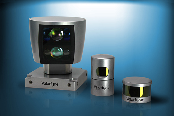
The LIDAR installed on the roof of the autonomous vehicle usually has a laser beam of no less than 16, and common types are 16/32/64 line LIDAR.
Single-Line LIDAR

Single-line LIDAR is currently the lowest cost LIDAR. The low cost means it is highly likely to be mass-produced.
In the news article about the first autonomous driving test site in Beijing that was recently circulating on social media, Foton Autonomous Vehicle used four single-line LIDARs arranged at the front, rear, left, and right of the vehicle to detect obstacles around the vehicle, as shown in the figure below.The principle of a single-line LiDAR can be understood through the following figure.

A single beam laser emitter rotates uniformly inside the LiDAR and emits a laser every time it rotates a small angle, generating a complete frame of data after a certain rotation angle. Therefore, the data of a single-line LiDAR can be regarded as a row of points at the same height.
The data of a single-line LiDAR lacks a dimension and can only describe linear information without describing surfaces. As shown in the above figure, the LiDAR can detect a cardboard in front of it and know the distance to the cardboard, but cannot obtain its height information.
Four-line LiDAR

Most four-line LiDAR systems are like the above figure.
The all-new Audi A8 is equipped with a four-line LiDAR system, ScaLa, located under the car’s grille to achieve level 3 autonomous driving.
With the introduction of the principle of a single-line LiDAR, the operating principle of a four-line LiDAR is easy to understand.
As shown in the figure below, different colors represent different laser emitters.

A four-line LiDAR switches between its four laser emitters, and after one switching cycle, it obtains a frame of laser point cloud data. The four sets of point cloud data can be combined to form surface information, which provides height information of obstacles.
The distance information of obstacles can be obtained from the coordinates of a single frame of point clouds.
The speed information of obstacles can be obtained by differentiating the distance information of multiple frames of point clouds.After purchasing a LiDAR product, its supplier also provides a software development kit (SDK) for the convenience of obtaining accurate point cloud data. Moreover, in order to facilitate the development of autonomous driving, the SDK even outputs processed obstacle results directly.
The green rectangular box in the following picture represents the position of the obstacle relative to the vehicle, and there is a small triangle at the front of the rectangular box indicating the direction of the obstacle’s motion.

16/32/64 Line LiDAR

The 16/32/64 line LiDAR has a 360° perception range and is often installed on the top of unmanned vehicles to maximize their advantages. The technical parameters and costs of the three LiDARs are shown in the following figure.

After the 360° LiDAR data is visualized, it is the effect that everyone often sees in various promotional materials, as shown in the following figure.

Each circle in the figure represents data generated by a LiDAR beam. The more LiDAR beams, the better the detection effect on objects. For example, the data generated by the 64 line LiDAR will make it easier to detect curbstones on the roadside.
The 16/32/64 line LiDAR can only provide raw point cloud signals and does not output obstacle results directly with a corresponding SDK. Therefore, major autonomous driving companies are researching algorithms based on point cloud data to complete the perception of unmanned vehicles.
LiDAR Data
The point cloud data structure generated by the LiDAR is relatively simple. Taking an N-line LiDAR as an example, the point cloud data structure is explained below.
In actual unmanned driving systems, each frame of data has a timestamp for subsequent time-related calculations (such as differential distance information). Therefore, the point cloud data structure for an N-line LiDAR is shown in the diagram below.# Translation
Translate the following Chinese text in Markdown format to English Markdown format, in a professional way, preserving HTML tags inside Markdown, and only return the result with corrections and improvements, without explanations:

The data structure of each line point cloud is composed of the number of point clouds and the data structure of each point cloud. Since the data acquisition frequency of the LIDAR and the number of point clouds per line can be set, the number of point clouds needs to be included in the 1-line point cloud data.

The lowest level is the data structure of a single point cloud. The point can be represented using polar coordinates theta/r or 3D coordinates x/y/z.
In addition to coordinates, each point cloud has an important element, which is the reflection intensity of the laser. The reflection intensity of the laser on different materials is different. Taking the 3D coordinate representation method as an example, the data structure of a single point cloud is as shown in the figure below. The offset in the X/Y/Z direction is based on the installation position of the LIDAR as the origin.

What can LIDAR do?
The general processing of LIDAR point cloud data is: data preprocessing (coordinate transformation, noise reduction, etc.), clustering (based on point cloud distance or reflection intensity), feature extraction of clustered points, and classification based on features.
Taking the functions currently available in Baidu Apollo 2.0 as an example, let’s see what LIDAR can do.
Obstacle detection and segmentation

After using high-precision maps to define regions of interest (ROI), we can utilize fully convolutional deep neural networks to learn features of point clouds and predict relevant properties of obstacles, obtaining foreground obstacle detection and segmentation.
Passable space detection

After high-precision maps limits the ROI, the height and continuity information of point clouds within the ROI (such as drivable roads and intersections) can be used to determine whether the point cloud is passable.
High precision electronic map mapping and positioning## High-precision Map Making through Combination of Point Cloud Information and Inertial Navigation System (INS)
By using the point cloud information from the multi-line LiDAR and INS data collected by the vehicle, we can produce high-precision maps. Autonomous vehicles utilize LiDAR point cloud information and high-precision maps to achieve high-precision positioning.
Prediction of Obstacle Trajectories
By identifying the topological relationships between the perceptual data from the LiDAR and the obstacles on the road, we can predict the trajectory of obstacles. This information can be used as the basis for decision-making for autonomous vehicles to avoid obstacles, change lanes, pass other vehicles, etc.
Conclusion
Although current AI algorithms are not yet mature enough, the safety of purely vision-based autonomous driving solutions remains problematic. Therefore, LiDAR is still essential in the development of autonomous driving technology. Even for industry leaders like Google, there are no LiDAR-free autonomous driving solutions available yet.
However, the cost of LiDAR remains a major issue for widespread use. After all, a sensor that is more expensive than the car itself is not acceptable for automakers. The road to cost reduction for LiDAR is a long one.
In summary, this article provides insights into the LiDAR sensing technology used in autonomous driving.
This article is a translation by ChatGPT of a Chinese report from 42HOW. If you have any questions about it, please email bd@42how.com.