Foreword
If vehicle intelligence is the future, then intelligent electrical architecture must be its foundation.
In the previous article, we mentioned that Tesla’s three distributed area controllers have basically achieved intelligent electrical architecture. But does understanding how Tesla achieved this mean that you can guide Volkswagen and Ford to achieve intelligent electrical architecture? Obviously not, as Zhang Xiaoyu said, the science of eggs turning into chickens can guide chickens, but how can it help ducks?
This article will start by analyzing the electrical architecture of Tesla, Volkswagen, and Ford’s three new SUVs. It examines why Tesla can lead the industry by 6 years in implementing intelligent electrical architecture, and how the historical burden of traditional car companies hinders the implementation of new technologies, from the system design of the vehicle to understanding the cost model and technological model, and finally the technical difficulties faced during implementation. This article is a detailed analysis of how to achieve the implementation of intelligent electrical architecture.
This article covers both passenger and commercial applications, and also introduces some basic knowledge of vehicle electrical principles, traditional device cost solutions, semiconductor solutions and costs, wire harness basics, basic load characteristics, HSD chip basics, MOSFET basics, the relationship between current and cost, related electronic electrical design difficulties, and chip parameter selection. It is a starting point, and I hope to work with industry colleagues to jointly promote the implementation of intelligent electrical architecture.
Body:
The automotive industry is currently undergoing a dramatic transformation towards electrification and intelligence. This transformation will inevitably lead to an increase in the number of vehicle ECUs and an increase in the complexity of electrical architecture. What will traditional car companies do during the architecture upgrade process? What considerations are there?
Coincidentally, using the Tesla Model Y as a basis, the foreign website “3IS” compared the electronic and electrical architectures of the Volkswagen ID.4 and Ford Mach E. These three cars are all pure electric SUVs, produced around the same time, and Volkswagen and Ford are traditional, old-school, large car companies. Therefore, comparing them with Tesla is very representative.
From the comparison table of the ECU and network type nodes in the figure below, we can see that the number of ECUs in Model Y, ID.4, and Mach E is 26, 52, and 51, respectively. Tesla’s integration degree is obviously much higher. This is mainly because Tesla has integrated the functions of many small ECUs into the area controllers. As mentioned before, for example, Tesla’s Model 3 FBCM is responsible for power distribution, as well as some left front light control, air conditioning control, heat management, and other functions that span the traditional body, cabin, chassis, and power domains.
As we mentioned before, traditional OEMs have a large historical burden. According to past experience, reusing existing mature modules can significantly shorten the vehicle development cycle and reduce development costs, while ensuring the reliability of the vehicle. But if you take too big of a step at once and engage in large-scale integration, it will cause problems across the board.Therefore, for traditional automakers, any change needs to be very cautious because there are many constraints, making it difficult to implement, with a long time frame, broad involvement, great risk and high cost.
As we all may remember, when ID.3 first hit the market, there were numerous software bugs, causing tens of thousands of cars to be parked at Volkswagen plants waiting for upgrades. If this could happen to Volkswagen, it’s even more imaginable with other brands. Therefore, we can see that both Ford and Volkswagen, despite claiming to have a brand-new pure electric architecture, still reused many small ECUs.
However, one undeniable fact is that Volkswagen has made significant updates in its electronic and electrical architecture upgrade process. If you’re interested, you can compare Audi e-tron and ID.4 electronic and electrical architectures to see the significant changes.
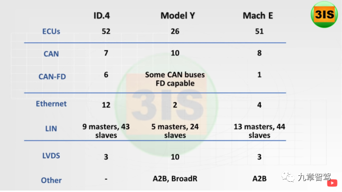
As shown in the figure above, you can see that the number of Lin bus lines in ID.4 and Mach E are almost twice that of Tesla’s. This also proves that they reused many small Lin-based communication ECUs, which is a typical traditional design approach.
In the previous two articles, we’ve thoroughly analyzed Tesla Model 3’s intelligent power distribution scheme and electrical architecture. If you’re interested, you can also check out “Why Does Tesla Want to “Kill” Fuses and Relays?” and “What Kind of Electrical Architecture Do Autonomous Commercial Vehicles Need?” From the table below, we can also understand the impact that intelligent electrical architecture has on vehicles from another perspective.
As you can see, both ID.4 and Mach E are still following traditional design methods, with three distribution boxes, one in the front cabin and two in the driver’s cabin, with a large number of relays and fuses. However, the Model Y adopts the same design as the Model 3, replacing all traditional relays and fuses with semiconductor solutions, with 0 traditional relays and fuses.
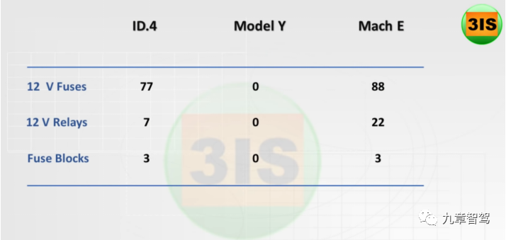
Such design differences lead to significant differences in electronic and electrical architectures among Volkswagen, Ford, and Tesla, even though they all adopt domain controller architecture concepts.Tesla’s architecture is closer to the regional control architecture, which is confirmed by the progress from the Model S with an internal cable length of up to 3 km to the Model 3 with only 1.5 km, as regional architecture has significant value in saving cable length. Aptiv has also calculated that using regional architecture can reduce cable costs by 25%, while Visteon believes that regional architecture can save 50% or more of the cable length.
In addition, Visteon specifically explains the value of regional intelligent distribution, including:
-
Dual power supply hierarchical power supply;
-
Promoting the electronic technology of power distribution and eliminating traditional fuses;
-
Central distribution box virtualization, optimized protection characteristics;
-
Intelligent power management, fault prediction based on current and voltage diagnosis;
-
Other values brought by optimized fuses and loads.
Actually, we have conducted multiple in-depth analyses of these things in our previous articles. Can it be said that Volkswagen and Ford do not understand regional architecture, or have not analyzed the value brought by regional intelligent distribution? The Model 3 was launched in September 2017, while Volkswagen and Ford began mass production in 2020 and 2021, with three or four years in between. However, Tesla is still the only OEM in the world that uses regional intelligent distribution, which is enough to explain the problem.
In addition, the conclusion given by 3IS is also interesting – 3IS said: “It is difficult to simply say whose architecture is the best, which depends on the purpose and constraints. Traditional OEMs can reduce research and development costs by continuing to use technology, although this is not the best way. Tesla has no choice but to start from scratch, so it can take a completely different path without any constraints.”
 Actually, Tesla does have restrictions on old car models. For the Model S released in 2012 and Model X released in 2015, Tesla can only adopt this technology on all new cars starting in 2022, counting from the first use of their intelligent power distribution solution on the Model 3. This has been a gap of 5 years, which is a clear indicator of the difficulty of upgrading and transforming old car models. This is even on the basis that Tesla has a mature smart area power distribution architecture.

Additionally, through the analysis of Tesla’s old car models, the Model X (2015-2020) and Model S (2016-2020), we can see that even with traditional power distribution box schemes, Tesla’s design differs from traditional OEM.

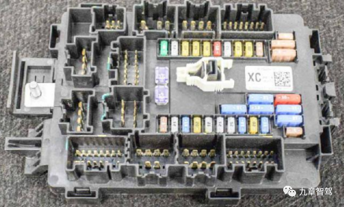
From the above images, we can see that Tesla’s entire car uses very few plug-in relays, only 5 compared to nearly 20 in traditional cars. There are only fuses in the cabin distribution box without any relays, which laid the foundation for Tesla’s innovative architecture in the Model 3’s intelligent power distribution. In comparison, the ID.4 and Mach E produced five years later have 7 and 22 plug-in relays, respectively.
So, why is the difference in electric architecture between Volkswagen, Ford and Tesla so large? Next, we will analyze in detail the difficulties in the implementation of intelligent electric architecture from the perspectives of system, cost, perception, and technology.
Vehicle System Perspective
As we mentioned in the previous chapter, many designs in cars are actually interconnected because cars are a very complex integrated system with tens of thousands of parts and many interrelated systems. For example, let’s take a look at Tesla’s “Do Not Discharge High Voltage” strategy, which involves a lot of specific designs:
-
After the Tesla Model 3 is parked, the high-voltage power battery will remain connected, and the high-voltage battery will discharge at a rate of about 1% per day.2. The “static” working current of Model 3 is 2.6A, while the static current of vehicles under traditional high voltage is around 15mA-20mA to ensure that the battery is not drained and can start normally next time (low voltage cannot be powered on high voltage, because BMS and VCU are powered by a 12V battery).
-
Such a large current will quickly drain the lead-acid battery, estimated to take just one day, so Tesla pioneered the design of integrating BMS with a small DC-DC for providing 12V power to the whole vehicle after parking to prevent battery drain.
-
The original intention of this design is to support all online services, such as Sentry Mode.
-
This design has also led Tesla to directly cancel the high-voltage pre-charging circuit, which is estimated to be a global first.
-
Tesla has adopted a little-known low-voltage battery DC-DC inverter for high-voltage pre-charging. This design does not support frequent high-voltage on/off, so the corresponding design is that Tesla’s high-voltage system generally does not power off after the first power-on.
From this, it can be seen that the implementation of a feature needs to be coordinated with the entire system design. This is just the high-voltage part, which involves the new design of pre-charging, BMS, DC-DC, and other modules and strategies. In fact, Tesla also has corresponding designs to support low-voltage power distribution and control.
Therefore, if we do not analyze the implementation of a feature from the perspective of the entire vehicle system, and try to introduce many new features and integration designs all at once, it will cause ripple effects and difficulties in making changes. Many factors must be considered and long cycles, wide coverage, high risk, and high cost must be taken into account.
The scene of tens of thousands of ID.3 waiting to be upgraded at Volkswagen’s factory is still fresh in our minds, and even Tesla needs several years to upgrade its old models. Therefore, traditional OEMs have to be cautious and continuing to use existing designs has become the “best choice” due to cost considerations.The author has conducted a cost analysis on the electrical architecture of commercial vehicles and several major OEMs. Upgrading the entire electrical component section (excluding wire harnesses) to intelligent electrical architecture at least doubles the cost, which is absolutely unacceptable even for commercial vehicles that are not so sensitive to cost, let alone passenger cars that are extremely cost-sensitive.
The following picture was shared in our previous article. For the 12V system, the semiconductor solution is more expensive than the current 30A relays, not to mention fuses, which have the largest proportion in the distribution box. The cost increase is significant when the whole vehicle uses semiconductor solutions, especially in high current circuits.
We roughly listed the cost comparisons of various solutions below for everyone to feel.
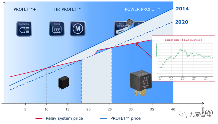


As an example, for a 10A circuit, a fuse costs only one cent, but a chip costs seven or eight yuan. However, the cost of chips is not linear with the increase in current level. For example, a 30A fuse costs only one cent, but a chip costs more than 20 yuan. When the current is even larger, HSD is no longer an option and we must use MOS solutions. Since there are so many fuses in the whole vehicle, especially in the primary distribution box where there are many high current circuits, the cost comparison of intelligent distribution boxes is unbearable. Even if you are a Tier 1 supplier, you may not want to raise costs with OEMs.
What should we do?
As a disruptive technological innovation, intelligent electrical architecture brings innovative value while also increasing costs significantly. If we want to promote and apply this technology, someone must pay for the innovation cost. However, OEMs don’t want to directly increase costs, which would directly impact profits. For traditional OEMs that rely on selling cars to make money, this is unacceptable.Generally speaking, if the cost increase brought by the technology is between 20% and 30%, the technology is relatively easy to land. However, for intelligent electrical architectures, the cost reduction of wiring and R&D needs to be considered from a system level. But the cost of the whole system is difficult to estimate. Even if OEM acknowledges the cost reduction, it is still difficult to calculate specifically, which makes it difficult to pass the cost hurdle. It’s hard for OEM leaders to decide on this technology.
Philippe Dupuy of NXP believes that OEMs understand the value of semiconductor solutions and are the main drivers of vehicle electrification, and that the system-level and vehicle-level costs have been saved through calculations. But at the same time, he admits that semiconductor solutions have not made significant progress to date.
As Professor He Fan said, it’s impossible to solve all problems at the same time and in the same place. You need to change the constraints and adopt a different approach to solving problems. This is what we often say, “you can’t treat a headache by treating the head, but you can cure it by soaking your feet in hot water.” For intelligent electrical architectures, the problems caused by cost increases are the same, and we need to find a breakthrough.
The “Hardware Pre-Embedded + Software Paid” innovation model is a breakthrough for the implementation of intelligent electrical architectures. As we analyzed earlier, Tesla led the innovative model of “Hardware Pre-Embedded + Software Paid” by embedding hardware costs as part of the value, which could be recovered through software payment mode in the later stage.
In traditional vehicle design, the demand is defined from the beginning and the whole vehicle is not updated during the lifecycle, so highly customized low-cost hardware can be used, which is sufficient and not necessarily powerful. However, if the hardware is not powerful enough, the software and hardware will be difficult to decouple. The software and hardware cannot be separated, so it is difficult to cope with the changes in new demands, and the hardware cannot be redefined by software, which makes it difficult to realize “Hardware Pre-Embedded + Software Paid”.
Without the software payment model, OEMs cannot innovate with hardware pre-embedded models, or even have the idea. Because although innovation generates new value, this value is not reflected in the consumer end immediately, or the reflection is not direct. Therefore, nobody is willing to pay the cost of innovation, and the pace of innovation will be slowed down.
As we mentioned in the previous article, the construction of intelligent electrical architectures can correspond to the internal needs of OEM software capabilities, while also enhancing OEM’s brand premium and extending the value chain, providing the possibility for OEM to transform from a vehicle producer to a service provider.In addition to cost, another obstacle to the development of new technologies or new things should be people’s perception. Just like when the mobile phone integrated a camera with a resolution of only 300,000 pixels, no one thought that it had any real value, and people wondered whether to use a camera or stick to using a camera. As we all know, the value of mobile phone photography has slowly been recognized, and consumers are willing to pay for cameras with one billion pixels. Even the manufacturers can use this as a marketing point, which would have been unthinkable in the past.
For OEMs that currently sell cars as their main business, vehicle prices must be differentiated according to configuration because the cost of materials varies. If consumers want more features, they have to pay more when buying a car. If they don’t have the money when buying the car or didn’t buy the configuration initially, it will be difficult to add it later.
For example, in the powertrain system, if you buy a 1.5T engine, and then find that the power is insufficient, it is ridiculous to try to exchange it for a 2.0T engine, as you can’t just replace the engine. However, for electric vehicles, power can be increased through software on hardware if there is room to spare.
Another aspect is the perception of production and cost. When Tesla initially researched electric vehicles, battery costs were about $600 per kilowatt-hour. However, after analyzing it through first-principle thinking, Musk believed that the cost could be reduced to $80 per kilowatt-hour in the future. As everyone has seen, the trend has been for battery costs to continuously decrease as EV production increases. It is estimated that by 2029, the price of lithium-ion batteries will drop to around $60 per kilowatt-hour.
Here we cannot help but mention a law in the automotive industry that accurately predicts price trends, namely Wright’s Law. It says that as production accumulates to double, cost price will drop by 15%, and it will continue to decrease. Once it doubles again, it will drop by another 15%. The automotive industry has been following this law since 1900.
Based on Wright’s Law, a new product or technology, after the production increases four times, the cost can be reduced to half of the original cost. But if you don’t have this perception, you will face high costs and “give up.”
Therefore, considering the current stage and the cost issues related to intelligent electrical architecture, our only solution may be indirect, but in the future, intelligent electrical architecture will become part of regional infrastructure, supporting the development of new energy trucks and advanced self-driving technologies.
In the previous section, we analyzed the impact of intelligent electrical architecture on costs, including harness design, electrical design, EMC, and vehicle operation and maintenance.
For example, using energy management algorithms can achieve intelligent energy-saving and fuel-saving. A study by Bosch shows that the output of a generator at 100W is equivalent to 0.17L/100km fuel consumption, and the current in a 24V system is only 3.7A, slightly more than a 70W lamp. Therefore, energy management strategies can improve the economy of the entire vehicle electrical system.
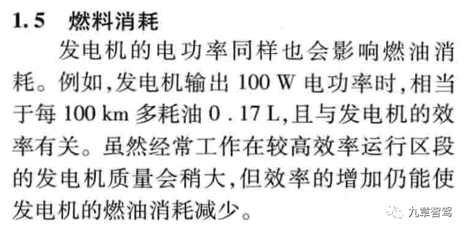
However, many decision-makers are overly concerned with direct costs and pay little attention to indirect costs. Therefore, the understanding of cost models will also hinder the promotion and application of many technologies.
Technical Mode Recognition
As we mentioned before, the automotive industry, as an industry with a history of over a hundred years, has many designs that are inherited, which means that there is continuity and little change. Traditional fuse relay technology has a long history, is reliable enough, has low usage costs, and is currently the best solution after considering both reliability and cost.
After exchanging technical ideas with many OEMs, the first reaction of most people is, “Is your technology solution without fuses reliable? Will it not fail to protect the wire?” Has your solution been installed and tested? Who has used it?
When facing new technologies, technical personnel in the automotive industry first consider whether your design is reliable or not. Has anyone done it before? Traditional technology can replace a burned-out fuse, but semiconductor technology requires replacing the entire module, which is too expensive and unreliable.
Regarding new electrical architectures, people’s inadequate understanding is mainly reflected in the following aspects:
(1) Reliability
In summary, the reliability of traditional electrical architecture has a high lower limit and a low upper limit, while the intelligent electrical architecture based on semiconductor solutions has a low lower limit but a very high upper limit!
We analyzed the aspect of reliability in detail in the article “Kill Fuses and Relays, and Self-driving Can Be Safer.” Please feel free to read it.Therefore, we cannot say that traditional solutions are already very reliable based on experience, because you haven’t had higher reliability requirements yet. Semiconductor solutions may not be mature and may be unreliable at the beginning, but we should believe that they can be very reliable. As the saying goes, eagles sometimes fly lower than chickens, but chickens can never fly as high as eagles.
Finally, let’s compare the reliability parameters in the table below:

(2) Surge current
OEMs who work on electrical issues are generally concerned about this issue. First, it is generally believed that semiconductor devices may be too sensitive, and the surge current at the moment of load start-up may cause accidental protection. In addition, it is believed that semiconductor devices cannot withstand the surge current of the load, which may cause damage. In the previous articles, we did not provide a detailed analysis of the surge current characteristics of the load. Here, we will briefly talk about it:

Let’s take a look at a few surge current waveforms:

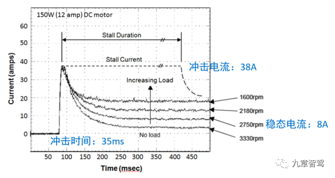
As you can see from the above figure, the surge current of capacitive load is around 10 times, while that of inductive load is between 3-5 times. Let’s take a look at the surge current capability of semiconductor devices below:
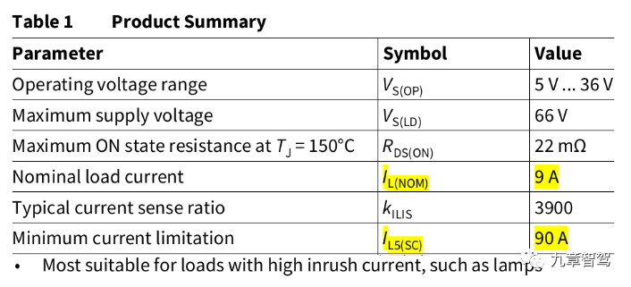
As shown in the above table, the surge current capability (i.e. limitation current) of the HSD chip is 10 times the rated current, which is sufficient to deal with all types of capacitive loads (except pure capacitors, large capacitors must be pre-charged). At the same time, the HSD chip only limits the output current to a certain value, rather than triggering protection and turning off the load. This is an application scenario that the chip designer has already considered when designing the chip.As for the inductive load with 3-5 times surge current, there is no problem. Now let’s take a look at the surge current capability of MOSFET. We take the power MOS used by Tesla for parameter analysis.
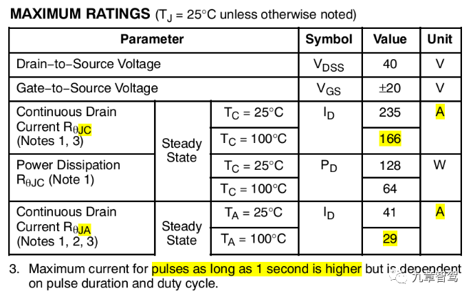
This is a 40V NMOS that can be used in 12V systems. The parameter is 1.3mΩ, 235A. It means that if you provide sufficient heat dissipation, it can handle a current of up to 235A. Practically, no one would dare to use it like that. You cannot cool it with liquid nitrogen, we need to consider engineering implementation. According to the author’s experience, with proper heat dissipation design, the MOS with 1.3mΩ resistance can easily handle over 40A in the full temperature range (-40℃ to 85℃), which is quite conservative since it is 29A at 100℃ (as shown in the parameter table).
Let’s talk about the pulse current. At 100°C, the MOS can handle 166A, which is more than 5 times higher than the rated current. This parameter represents the transient current with a longer duration, which is similar to the impact of inductive load. Therefore, it can easily handle the surge of 3-5 times the rated current of inductive loads. We can also see from the remarks that even the pulse of 3.1 seconds is no problem.
Some of you may ask, why do I talk about capacitive loads when analyzing HSD, and inductive loads when analyzing MOS? Because HSD can handle small-capacity loads, and these loads are usually small, even 10 times the surge is not a problem. For high-current applications, there is no corresponding HSD chip and only MOS can be used. Moreover, high-current loads usually have inductive characteristics, with longer surge time but smaller multiple. It is just like the application of traditional fuses: chip quick blow fuses are used for small current to resist high-multiple short pulse, and the requirement is for fast protection; while plate slow blow fuses are used for large current to resist high-current long-time surge, and the requirement is for reliable protection. Although there are two technical lines, they have similar characteristics.
(3) Rated Current
We have analyzed this problem in detail in the previous article. Here, we only give the conclusion: under the intelligent electrical architecture, the load capacity of the distribution module can be matched according to the rated current of the load.
The OEM’s electrical design has always been based on the knowledge of matching current with fuses. Therefore, they will compare the rated current of traditional fuses with that of chips. For example, if a 20A fuse was used before, they would require the chip to use 20A as well. This understanding is incorrect, and we need to abandon the thinking of fuses and focus on the real load situation. The following figure is a simple and clear comparison, which is presented again here:
Generally, compared to the original fuse design, the rated current of chip design can be smaller, even as small as half of the original, and the wire diameter design is correspondingly reduced.
Therefore, based on the future intelligent architecture of chip design, everyone must change their awareness. When someone says the current is 20A, you have to ask if it is the previous fuse with 20A, or if the rated current of the load is 20A. Otherwise, there will be communication problems due to different understandings, and the current level is directly related to costs. The cost difference between 10A and 20A chips is not proportional to twice the cost. Another value is the reduction in the cost of wiring harnesses and the simplification of electrical design. These have already been discussed in detail before.
(4) Power attributes
The concept of power attributes is well-known in the automotive industry. After all, it has been used for so long. Even the well-known terms like KL15/KL30 were proposed by Bosch in 1984, showing its long history. The reason for defining power attributes in the past was to facilitate energy management. However, after switching to intelligent electrical architecture, you will suddenly find that power can no longer be classified with attributes. All circuits can be defined as any power attributes, and fixed power attributes are no longer needed.
The value brought by arbitrary power attributes includes but is not limited to supporting more free and complex energy management strategies, optimizing the overall vehicle electrical architecture design, optimizing the wiring system, and network management design.
(5) Each circuit is independently controllable
In traditional architecture, the vast majority of circuits are uncontrollable. For example, in the constant electric circuit, when the entire vehicle is powered on, these circuits are also powered on, and you cannot turn them off. Passenger cars have no master switch, so static power consumption management is necessary, while trucks rely on master switches to control power.
In intelligent electrical architecture, each circuit is independently controllable, but people who are used to traditional electrical design may not have this understanding. In traditional experience, how can so many circuits be independently controllable? Therefore, they cannot realize the value brought by independent controllability.
Other values brought by intelligent electrical architecture include: cancelation of the power master switch, power consumption control and energy management, optimization of wiring harnesses, configurability, programmability, upgradability, and iterative improvement. We’ve analyzed these in detail in the previous two articles, and readers who want to know more can go and take a look.
(6) Independent protection for each circuit
In traditional architecture, power distribution must be hierarchical, similar to waterfall architecture. All secondary circuits have a primary big fuse and are distributed to multiple secondary small fuses before reaching the power-consuming equipment. If there is a problem at the primary level, many secondary levels will be affected.# Traditional vs Intelligent Electrical Architecture in Automotive Industry
In traditional design, fuses are responsible for protection while relays are responsible for control. Protection and control are naturally separated. If one load has a problem, all loads will be disconnected if using shared protection and separated control.
However, in intelligent electrical architecture, due to increased reliability and the absence of power attributes, the power supply of secondary distribution is much less. Therefore, all secondary terminal equipment can be considered parallel to the primary, rather than in series. This means that the protection of the secondary circuit is actually independent.
The natural advantage of using intelligent electrical architecture is that circuit protection and control are integrated, and all circuit protection is naturally independent and unaffected by other circuit faults.
(7) Protection and Diagnostic Functions
We have discussed this point in detail in our previous article, so here are a few basic points:
-
The protection can be recovered, and the recovery conditions can be software-defined, such as relying on the ON gear, switch signal, or power on/off.
-
Customizable overload protection, which is not supported by traditional fuses.
-
Current detection function
-
Open circuit detection function (ON/OFF status)
-
Voltage detection function (overvoltage/undervoltage)
Some Tesla enthusiasts have tested the self-recovery protection function of eFuses in the 2022 Model S and found that it can indeed automatically recover after the fault is resolved, such as the 12V accessory power socket. However, some functions may not automatically recover, such as the drive control button. The tester found that the output was immediately protected when the load was increased from 400mA to 1.5A. At the same time, precise information was provided on the central control screen fault alarm, including which function had a fault and how to check it. The tester said that this fault did not self-recover, but rather it was only after the software upgrade of the entire vehicle that it was restored. Therefore, the specific recovery conditions depend on the software strategy.
Because traditional architecture does not have diagnostic functions, people basically have no awareness of this area, it’s a blank area. Just like when you are using a functional phone, you cannot imagine the impact brought by a smartphone, including mobile payments, QR codes, and other applications, are all new applications derived after smartphones gradually became popular. Based on the protection and diagnostic functions of intelligent electrical architecture, various new applications can also be derived, new value can be generated, and it can have a huge impact on the intelligentization of vehicles.
 Ignoring the system dimension and cost factors mentioned earlier, changing people’s perception of a new thing may be more important in some sense than all other efforts. As a disruptive innovative technology, intelligent electrical architecture can bring about a value far beyond our imagination. Therefore, only by changing our perception of it, breaking the limitations of traditional thinking, can we then explore its potential value, assess its impact on the automotive industry, and jointly promote its landing.
Technical Perspective
In the previous chapter, we analyzed the problems faced by intelligent electrical architecture from the perspectives of system, cost, and perception. In this chapter, we will talk about the technical issues that will be encountered if we adopt intelligent electrical architecture.
Technical Categories
Before talking about this issue, let me share with you a personal experience. When taking a purely electric-powered taxi, I usually chat with the driver and ask about issues such as the endurance, cost per hundred kilometers, driving experience, and differences with fuel-powered cars. I found that many drivers generally feedback that repairing electric cars is very expensive. Even if it is a small issue, they dare not fix it themselves, but instead have to go to a 4S store as ordinary roadside shops cannot handle them. Why is that? Let’s think about it.
Most of the problems with fuel-powered cars are mechanical problems, which are visible to the naked eye. After electrification, the mechanical problems of electric cars are extremely rare, and the problems become electrical, electronic, or software issues, which are no longer visible to the naked eye. Therefore, the technical requirements for fault diagnosis have increased, and as electric cars are a relatively new thing, people naturally do not understand them and are afraid to touch them.
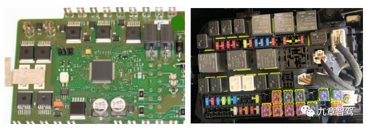
From traditional architecture to intelligent electrical architecture, similar problems can also be encountered. The traditional electrical architecture is entirely in the mechanical and electrical categories and belongs to the electrical department at OEM, unrelated to electronics. However, after upgrading to intelligent electrical architecture, it becomes fully electronic.
The traditional distribution box belongs to the labor-intensive industry and competes on low cost. The design does not require high technical content, but after being electronic, the original traditional distribution box manufacturers are baffled, and OEM’s electrical department does not understand either. Although the electrical schematic of the intelligent distribution box seems simpler, it is still treated as a black box because there are software logic and configuration in the middle, which rendering it useless to just look at the schematic.
In addition to the cognitive and technical ability levels, there are also some technical issues that were not given much attention before.When it comes to load characteristics in traditional electrical architecture, electrical design can be done without much concern because fuses are already graded and one can choose between 10A and 15A, while the wire gauge is usually sufficient as well. Experience is often enough to get by, relying on fuses to solve any issues that might arise. However, in intelligent electrical architecture, understanding load characteristics is essential for electronic design, which we will analyze in detail later.
Here, we will briefly explain a small piece of knowledge about vehicle wiring. The overcurrent capacity of automotive wires is actually far greater than most people imagine. To put it in extreme terms, let’s look at the amount of time it takes for a wire to emit smoke when subjected to a certain current. (This can vary depending on the type of wire; some wires do not emit smoke at all.) Vehicle wires can withstand 5 times their rated current for 5 seconds without emitting smoke, whereas even slow-blow fuses will burn out at 5 times the current within 1 second.
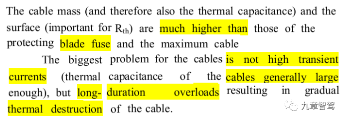
As shown above, vehicle wires have extremely strong short-term overload capacity, far surpassing the capabilities of the blade fuse. The main issue with improper use of wires is insulation damage caused by prolonged overload heating.
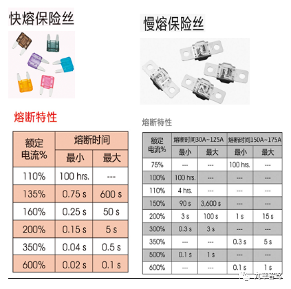
The above table shows that no fuse can withstand 5 times the current for 5 seconds.
Therefore, traditional distribution box manufacturers face various issues when entering the intelligent electrical architecture, including but not limited to:
- Understanding of the electronic system, including electronic electrical architecture, control logic, network communication, etc.
- Experience in electronic product design, including system, hardware, and software design
- Electronic product testing methods and reliability design
- Automotive electronic test standards, including electrical, environmental, durability, ESD, EMC, etc.
- In-depth understanding of load characteristics and operating modes
- Balance between design scheme selection and cost.
So, if traditional distribution box manufacturers can’t handle it, what about manufacturers who specialize in electronic modules? Indeed, they know electronic design, but this statement is only partially correct; they only have expertise in small current electronic design, while the entire vehicle electrical architecture and high current design are outside their areas of expertise.
Therefore, traditional electronic module design manufacturers face various issues when entering the intelligent electrical architecture, including but not limited to:
- Understanding of the entire vehicle’s electronic electrical architecture, electrical principles, and electrical design
- Whole vehicle energy management, up and down voltage strategies
- Types of loads on the vehicle, load characteristics
- Protection characteristics and wire harness matching (traditional fuse matching is based on experience and recommended design).- Shell design, including heat dissipation, protection level, installation method, etc.;
- High-current wiring design, including connectors, bolts, etc.;
- High-current board-level design, including device heat dissipation, PCB current carrying capacity, etc.;
- High-current device selection, understanding the characteristics and parameters of MOSFET, etc.;
- Testing and verification methods for high-current products.
Traditional electronic module manufacturers are generally lacking experience in board-level high-current design solutions. Not to mention other things, just take Tesla’s board as an example, with such large busbar current-carrying design, most people have never seen it before. Because in electronic design, current generally does not exceed 10A, mostly at the mA level, and static power consumption is generally at the µA level. People have no concept of hundreds of amperes of current, let alone imagine it. Even more, traditional electronic module manufacturers may not have corresponding DC power supply equipment (commonly used DC power supplies are within 30A, and the maximum is not more than 100A), and have not seen wires exceeding 4 square meters (the wire diameter of household wires is generally only 4 square meters).
In my opinion, traditional distribution box manufacturers have difficulty in transformation because there are too many knowledge blind spots involved. From hardware design, software development, to electronic product testing experience, and knowledge structure, they are all different, so it is difficult to make up for them.
It is also not easy for traditional electronic module manufacturers to cross over to electrical design. For example, understanding of the overall electrical principle of the vehicle, electrical design, and in-depth understanding of load characteristics, as well as design aspects of traditional distribution boxes, such as structure, electrical and wiring harness, etc., have different knowledge structures. There are many pitfalls in this area, such as what size bolts to use for high-current wires and what torque range is required for assembly. Traditional electronic module manufacturers have no concept of these things.
Therefore, in my opinion, Tier 1, which combines the ability to design both traditional distribution boxes and electronic modules, is most likely to achieve the landing of intelligent electrical architecture. They can integrate the two departments that have never been related in the past and work with the OEM to complete the design of intelligent electrical architecture and gradually put it into practice.
Chip Solution Issues
For low-current design, it’s fine to use mature integrated chip solutions (HSD high-side chips). This was analyzed in the previous article. Applications below 25A for passenger cars are very mature, and applications below 10A for commercial vehicles are available.
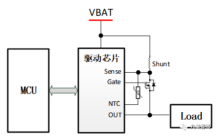
For high-current solutions, there are currently mature 30A HSD chips available for passenger cars, and the current rating will continue to increase in the future. However, as far as commercial vehicles are concerned, according to my understanding, major chip suppliers do not currently have new roadmaps. The high-current solution can only use a separate solution of drive chips + MOSFET. This solution has the following problems:
- The overall solution is complex, and the comprehensive cost is high;
- Current detection is complex and costly (shunt+amp op amp scheme);
- Few protection functions, slow protection speed;
- Few diagnostic functions, complex diagnostic function design;
- High-current applications require MOSFET parallel design.
This solution requires adding corresponding discrete circuits according to application needs. If current detection is required, shunt and amp must be added, including protection and diagnostic functions. The more functions there are, the more complex the circuit is. Because most of the protection functions are implemented by MCU, it is not only slow but also has complex software strategies.
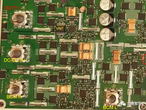
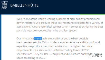
Let’s take a look at Tesla’s solution first so that everyone can have an intuitive understanding. The small black square in the figure below is the power MOSFET, the silver PCB busbar is used for high-current load, and the yellow brass shunt is used for current detection. High-current shunts are not available worldwide. Although they are just copper sheets, the requirements for materials’ accuracy and temperature coefficients are extremely high, which is considered a basic discipline material. A German company does this very well, but of course, it is not cheap.
In addition, although MOSFET has its corresponding rated current and pulse current parameters, SOA (Safe Operating Area) must be considered in the design, which is very important for MOS design. Special driver chips generally consider switch-related parameter designs such as MOS drive voltage, current, and junction capacitance charging and discharging time. However, if you create the circuit yourself, you need to consider more factors. Even if the driver chip has protection functions, it is generally limited to short-circuit protection (based on VDS) and MOS overheat protection. If the chip does not support current detection through shunt, other protection functions derived from current detection such as overcurrent protection, open-circuit protection, current limitation, etc., are complex to implement in the self-assembled circuit, including hardware circuits and software strategies.
Additionally, there is the issue of MOSFET parallel design that must be considered for larger current levels, and this requires high product hardware design consistency. Issues like PCB average current, transient energy, peak cut-off voltage, parasitic oscillation, especially for inductive load applications, cause inductive energy release issues. If not handled properly, the most fragile or the circuit with the minimum impedance will be damaged first.
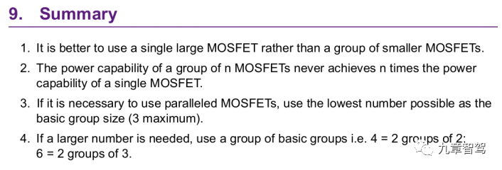
Below is the summary of IR/Infineon’s Power MOSFET parallel application. The first and third items mention current balance issue. Even if MOSFET is a positive temperature coefficient device, which naturally brings some self-balance advantages, there are still limitations (no problem at steady-state and switching state, but short-circuit issue is a big one, which is not mentioned below). The second item is the SOA (safe operating area) issue, indicating its importance.

By the way, let’s popularize some basic knowledge about MOSFET. The RDSON of MOS is the on-state resistance, whose unit is mΩ. The smaller the value, the larger the current, and the more expensive. The consistency and stability of automotive MOSFET itself are higher than consumer-grade and industrial-grade MOSFET. However, even MOS of the same batch have huge parameter differences because they may come from different wafers. Of course, these differences will not exceed the parameter range specified in the datasheet, but they still cause many problems in parallel applications.

Let’s directly look at the conclusion of this application document: not recommended for multiple MOSFET parallel applications (that’s obvious). The document believes that a single MOSFET with lower RDSON is better. Even if n MOSFETs are parallel, the final result cannot reach n times effect (unless you don’t care about the money. The first two suggestions are worthless. Actually, everyone knows that the cost does not allow it). Finally, if you really have to parallel, do not exceed 3 MOSFETs. Tesla does this by grouping parallel.
Those interested can refer to the application documents of NXP and Infineon, which will not be discussed in detail here.
Finally, let’s look at the cost and feel why everyone must use parallel.## NVMFS5C410N-D – Largest MOS Used by Tesla
NVMFS5C410N-D is the largest MOS used by Tesla, with a resistance of 0.92mΩ and costing $1.8 per piece. Those slightly larger, with a resistance of 0.63mΩ, cost $5.2, which is three times the price for only a small increase in current. The MOS with half the resistance, 2.3mΩ, saw a price drop of 37%, highlighting the disproportionate increase in cost for larger MOS. Therefore, as shown in the picture below, Tesla put 4 MOS in parallel to manage the DC-DC input, which is consistent with NXP’s recommendation. However, Tesla went one step further and put 4 groups of 4 MOS in parallel, daring to take a risk that other car manufacturers like Volkswagen and Ford would not take.

Load Characteristics – Reliability Issues
Reliability not only encompasses durability and failure rate, but also robustness. In the context of intelligent electrical architecture, the distribution box that implements the distribution and control functions must be functioning properly, which is more important than just having a box that is not damaged. If the functionality fails, even though the box is not damaged, it is unreliable from a user’s perspective. Therefore, the reliability here needs to consider the robustness, stability and resilience, which is contrary to the sensitivity and accuracy of semiconductor protection. Design is about balancing this contradiction, achieving stable operation and reliable protection, which is challenging given the varied load characteristics in different vehicles.
Normal Line Conditions:
1) The overload current of the load should not be protected.
2) There should be no protection for short-term overload of the load.
3) Protection can be restarted, and the line should return to normal after the fault is cleared.
Abnormal Line Conditions:
1) Hard shorts require fast protection.
2) Soft shorts are protected according to demand.
3) Appropriate protection speed should ensure that the wire is not damaged.
4) The protection device should not be damaged or inferior after the protection.
The traditional electrical design has a strong fault tolerance since there is large margin and less design constraints. For example, the cost difference between fuses of different current levels is minimal, and fuses require replacement and maintenance. This has led to the crude traditional electrical design.But in the era of electronic design, the design constraints have completely changed. For example, with the improvement of chip sensitivity, precise protection must be required, which necessitates accurate matching in the early stage of design, otherwise problems may occur later. For example, it could cause false activations or chip burnout when there is a malfunction. However, if the early stage has additional leeway, it will lead to too high BOM cost because the cost of chips is strongly related to current level.
Therefore, to achieve a balanced design in terms of cost and reliability, it is necessary to understand the characteristics and load characteristics of chips in detail. For example, HSD chips have rated current, current limiting parameters, temperature characteristics, and protection features such as overcurrent protection, short-circuit protection, and thermal protection. The driver chip + MOS scheme is more complex, and many protection features depend on specific hardware design and software strategies.
On the load side, whether the load is capacitive or inductive, the impact current waveform, peak, and duration all need to be considered. For motor loads, there is a need to consider whether there is overcurrent protection and stalling protection.
We have analyzed the load characteristics earlier, but in actual use, you will find that some appliances have multiple load characteristics. For example, some controllers are capacitive when powered on because the controller has an input capacitor. After working, if the controller controls the load of the motor, it becomes inductive, and for heating devices, it is similar to resistance. In addition, different load working conditions are also different, which requires an understanding of the electrical principles of the entire vehicle and specific functional applications.
Therefore, the reliability of the final functionality depends on the assumed load characteristics and working conditions in the early stage. If the load characteristics change, the application may have problems. If protection characteristics are difficult to design based on uncertain load characteristics, being strict may conflict with the load characteristics, leading to false activation; or being lenient may lead to an increase in chip leeway or no protection when necessary, which increases usage risk.
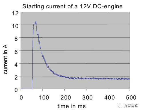
As shown in the above figure, this motor load has nearly 30ms of 5 times the rated current. If a protection strategy is designed specifically for this load, the surge current needs to be filtered out to ensure that it will not be falsely activated. Considering the uncertainty of motor stall time, the time needs to be extended. However, if the load changes to resistance, it may be that there is a broken wire or a ground fault in the wire harness that needs to be protected.
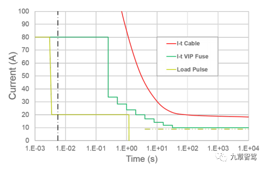 The above figure perfectly illustrates the relationship between wire harness characteristics, protection characteristics, and load characteristics. The yellow line represents load current/time characteristics, the green line represents device protection characteristics, and the red line represents wire harness I²t characteristics. Therefore, the following requirements must be met for the design:
-
The protection characteristics must envelop the load characteristics, otherwise there may be a false operation;
-
The protection characteristics must be within the range of wire harness characteristics, otherwise the wire may burn in case of malfunction;
-
The three curves must ensure no crossing over the entire temperature range.
We have analyzed in detail the influence of load characteristics on protection strategy, but without specific data comparison, it may not be intuitive. Thus, I will present a comparison of data:

Why have I been emphasizing load characteristics all the time in this article? With such load characteristics and fault parameters, let alone a design for general use, trying to establish a protection strategy for a specific type of load is already very difficult. Therefore, designing for a specific load is necessary to balance the reliability and cost of the design. From this perspective, the difficulty in designing passenger cars is far less than that of commercial vehicles. Those who design commercial vehicles can be a bit arrogant, even though their technology may be behind, their difficulty is greater.
Static Current Problem
As we analyzed earlier, traditional fuses have many advantages, including being simple, easy to use, inexpensive, and robust. However, there is one point that has always been overlooked: their current consumption as passive devices. As a piece of metal material, a fuse does not consume any extra current as a completely passive device, and can continuously protect the cable and prevent any short-circuit faults from occurring, providing protection at any time.
When the vehicle is running, this advantage of fuses cannot be demonstrated, but when the vehicle is parked, the entire vehicle’s demand for static current consumption is raised, and then the advantage of fuses is demonstrated. They can quietly protect the entire vehicle without adding any additional static current consumption, while semiconductors cannot. Maintaining the conductivity of a chip is a bit better, but it still requires several tens of µA. If protection functionality is also required (of course, without protection, there is a risk of burning the car when it is parked), then the current level must be in the mA range.
Here is another piece of knowledge: generally, for high-side drive schemes, whether using HSD integrated chips or driver chips plus MOSFETs, maintaining conductivity for one channel plus protection functionality generally requires around 5mA, which OEMs cannot accept (generally, passenger car OEMs require the entire vehicle to be around 15mA-20mA).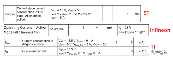
For example, if there are 5 functions that require constant electricity, an additional 25mA is needed. If the battery capacity is not large enough, the car will lose power after being parked for a period of time. For instance, if it could be parked for a month before, now it can only be parked for half a month. Imagine coming back from a long trip and finding out that the car can’t be started. How would you feel?
The following is a comparison between the vehicle battery capacity, static current, and number of days parked:

For commercial vehicles such as medium and heavy-duty trucks, the battery size is generally larger, often exceeding 100Ah. In addition, there is a main switch, and the fact that commercial vehicles are used to make money means that they are not likely to be left idle for ten days or half a month, as loans must be paid. Therefore, this aspect of the problem is better for commercial vehicles than for passenger cars.
In addition, the trend for pure electric vehicles is battery downsizing. For instance, Tesla uses a 33Ah battery because it doesn’t need to start the engine. As long as the high-voltage battery is not discharged, it will continue to be powered. However, if the high-voltage battery is discharged and the low-voltage static power consumption cannot be controlled properly, the battery will discharge. Even if the high-voltage battery is charged, the vehicle still cannot be started. Of course, pure electric vehicles only require the high-voltage contactor to be closed to start the vehicle, so the demand for remaining battery capacity is much lower than that of a gasoline vehicle’s starter motor. However, whether the relevant requirements can be reduced still requires further discussion.
Therefore, regarding the increase of static power consumption after electrification, Tesla has come up with a unique solution – the high-voltage system never loses power. This is a system engineering design aimed at supporting all online services and also conveniently solves the problem of static power consumption caused by the use of semiconductor designs. Of course, this increase of dozens of mA is insignificant compared to Tesla’s 2.6A static current.
However, this problem may truly be a problem for other OEMs, unless you can copy Tesla’s system design and convince your users. Not all users can accept a 1% decrease in high-voltage battery power consumption every day when parked. You cannot persuade customers without additional value. Moreover, the target audiences for different brands have a significant difference in their cognition, and their acceptance levels for certain designs differ greatly. For example, iPhone users can accept poor signal, small battery size, and no fast charging, but think about Android users.For gasoline-powered vehicles, the problem of static current not being able to drop when there is a constant electric load due to low-voltage lead-acid batteries is unsolvable unless there is a uA-level solution.
To address this issue, ST has launched a new automotive-grade driver chip specifically for high-side driving of external MOSFET applications, with a voltage withstand of up to 60V, suitable for passenger and commercial vehicle applications. This chip has a standby current as low as 70µA and provides protection while in standby.
Finally, to summarize, this article analyzes the difficulties of implementing intelligent electrical architecture from four dimensions: system, cost, cognition, and technology. The authors believe that cognition may be the most important and difficult aspect to change of the four. Intelligent electrical architecture, as a disruptive technological innovation, may be more important than all other efforts in changing people’s cognition.
Due to space limitations, some technical points have not been discussed, such as why MOSFETs can be designed in parallel but HSDs cannot, why high-side power supply designs must consume power, and what the differences are between automotive electronic engineering design thinking and traditional electronic design. Comments are welcome from readers, and we can continue to analyze these topics in the future.

This article is a translation by ChatGPT of a Chinese report from 42HOW. If you have any questions about it, please email bd@42how.com.
