Author: Zhu Yulong
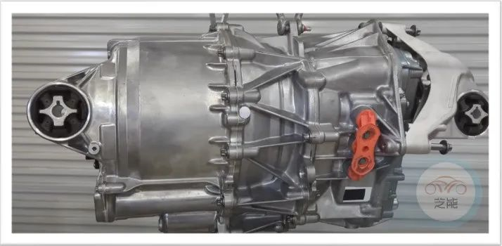
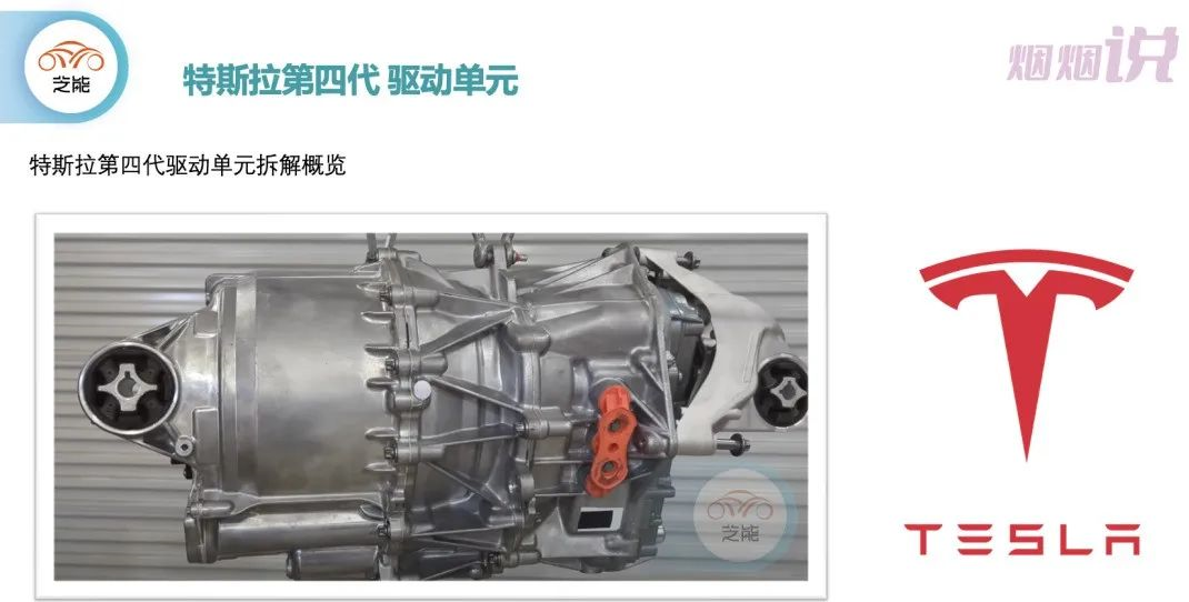
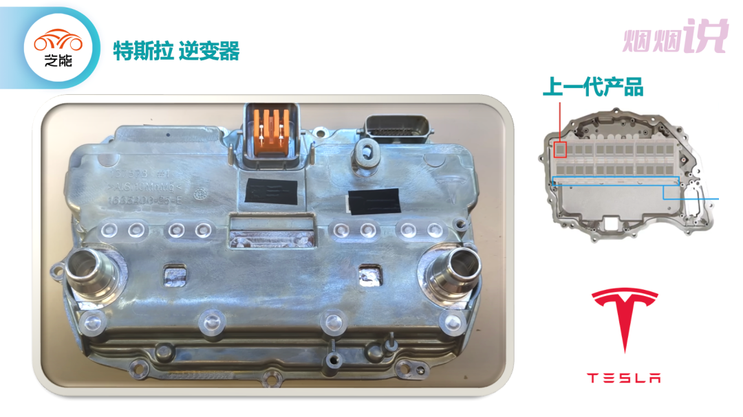
Tesla has introduced the fourth generation drive inverter in the Model Y, and this product has made some progress in continuous optimization, including:
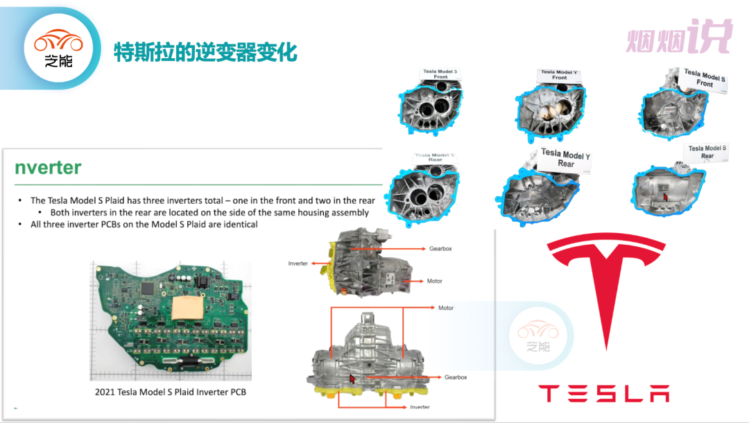
◎ Changed the section of the inverter from irregular to square
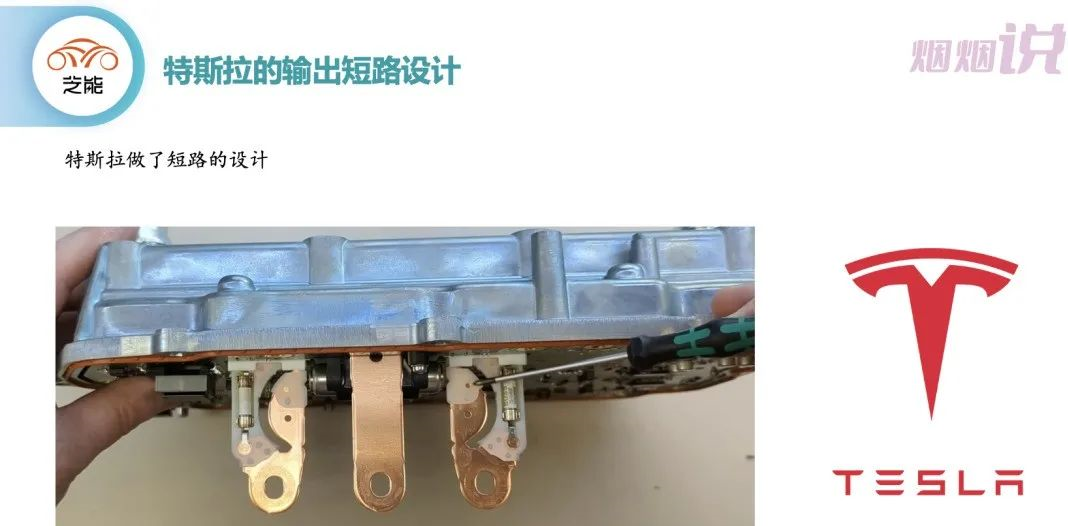
◎ Optimized the electrical protection (arc-pull design) for outputting three-phase electrical connections
◎ Imported two infrared temperature sensors
◎ Optimized the circuit of the Gate Drive driver
System Design Improvement
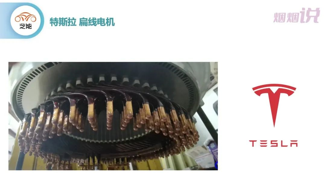
Tesla’s latest electric drive 4D1/5 was disassembled by Tesla dismantling master Ingineerix on Youtube. At present, it is divided into a basic version 4D5 and a performance version 4D1. From the disassembly image of the stator, Tesla uses 8 layers of HairPin and makes certain adjustments to the oil hole structure of the stator core.
Of course, the biggest change is still the design of the inverter itself, and we will take some time to clarify the basic situation.
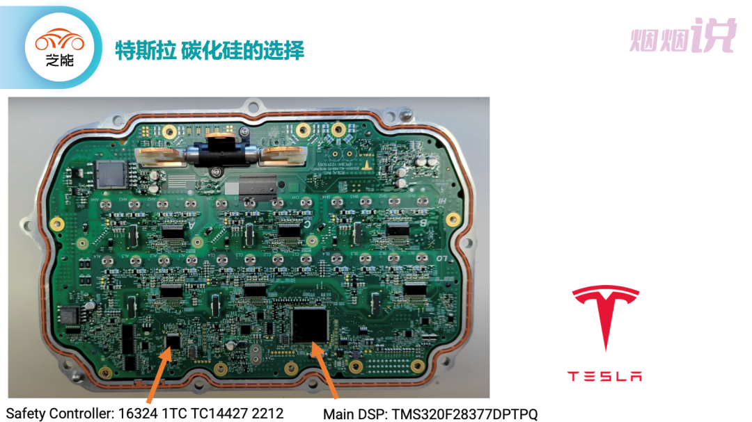
The overall control part has not changed much, and the main control part is mainly composed of two parts:
◎ Main DSP: TMS320F28377DPTPQ◎ Security controller: 16324 1TC TC14427 2212
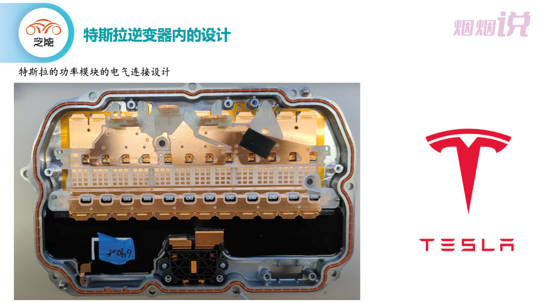
Design of the fourth-generation inverter
First of all, we can see that in the output part, the design of fuse and arc resistance has been added to increase the safety after collision.
One question that arises here is whether Tesla has designed power modules and reduced the need for SiC power module paving by 75%. Of course, it can be confirmed that some fine-tuning has been done in terms of technology and layout.
Of course, the specific design mainly includes:
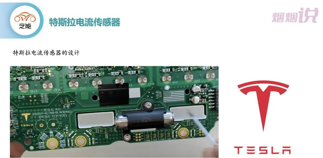
- Improving the design of current sensors
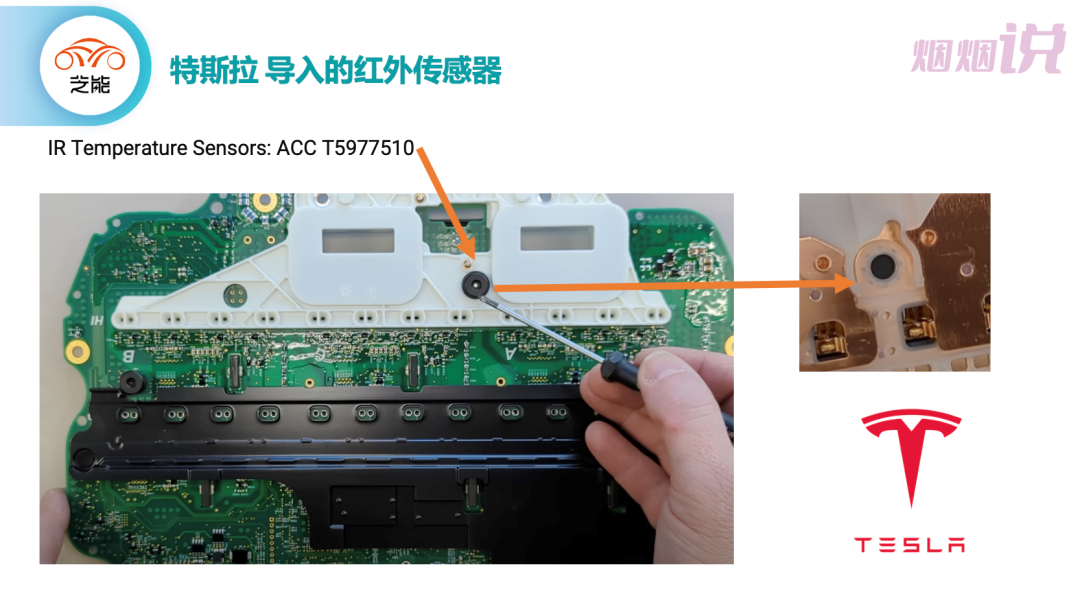
- Introduction of infrared temperature sensors
It mainly includes the introduction of two infrared temperature sensors, and the extensive use of temperature guns may have reduced the price of sensors (IR Temperature Sensors: ACC T5977510).
 – Improvement of Drive Circuit
An isolation transformer is introduced here, especially in the design embedded in the PCB, with a significant adjustment range.
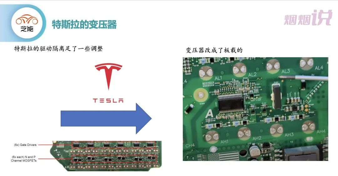
Of course, the discharge resistor has also been eliminated.
Summary: At present, the information is mainly guessed based on the video. When we get the real object in the future, we will also dismantle and analyze it for the first time to have a more on-site experience.
This article is a translation by ChatGPT of a Chinese report from 42HOW. If you have any questions about it, please email bd@42how.com.