Author | Xiao Shaohua
In the previous article “Details of Processing LiDAR Point Cloud Data“, the author mainly explained the process of processing LiDAR point cloud on autonomous vehicles.
During the exchange with LiDAR companies, downstream OEMs, or solution providers, the author found that perception algorithm engineers encounter many problems in the current process of processing LiDAR point cloud. For example, problems with point cloud noise, too much or too little point cloud, FOV design issues, overlapped areas of point cloud, and calibration parameter offset issues.
This article will explain the problems encountered in the point cloud processing process and corresponding countermeasures from two dimensions, namely technical and engineering.
Technical Problems and Countermeasures
1.1 Problems with Point Cloud Noise and Countermeasures
Point cloud noise refers to some invalid points collected by LiDAR, which can easily cause false detections of the target detection algorithm model. The main sources of LiDAR point cloud noise are twofold: on the one hand, noise caused by the target surface. For example, the properties of the target surface material (highly reflective surface materials cause the reflection energy of the point cloud to be too strong, making the target appear larger than the actual size), roughness (uneven surfaces cause the emission angle of the point cloud to change), etc.; on the other hand, noise caused by the external scanning environment, such as rain, snow, fog, dust and other particles, which obstruct the reflection of the point cloud.
As mentioned in the previous article “Details of Processing LiDAR Point Cloud Data“, the handling of point cloud noise mainly focuses on the filtering process in the preprocessing stage. Filtering processing is to handle noise from the perspective of algorithm application, but some noise cannot be simply processed by filtering algorithms. For example, environments like heavy rain or heavy snow cannot be directly processed by filtering algorithms. For example, for some telecommunications signals that affect LiDAR, filtering algorithms cannot be directly processed.
Next, the author summarizes several relatively typical noise factors and explains their respective problems and countermeasures in turn.
(1) Noise caused by object surfaces
When LiDAR scans some special object surfaces, some noise is caused due to the high energy (high reflection rate) of the point cloud reflected by the object surface.
For high-reflective target surfaces, laser point clouds often exhibit the phenomena of high-reflective “ghosting” and high-reflective “expansion”. Among them, high-reflective “ghosting” refers to the fact that laser radar is very sensitive to high-intensity echoes reflected back from high-reflective target objects. This causes not only a true point cloud image in the original coordinate system of the target object, but also an image of similar size and shape in other nearby positions. For example, traffic signs, license plates, tail lights, etc. High-reflective “expansion” refers to the fact that after the laser scans the high-reflective target surface, the point cloud image will show a phenomenon of spreading to the surroundings, making the original target point cloud image appear larger.
Regardless of whether it is high-reflective “ghosting” or high-reflective “expansion”, both may cause false detection, and both may force the vehicle to take unnecessary obstacle avoidance measures.
Point cloud noise caused by object surfaces can be mainly solved through hardware and algorithm levels.
At the hardware level, technicians strengthen the factory testing process of lidar products to enhance the resolution capability of lidar for high-reflective and low-reflective objects.
At the algorithm level, filtering algorithms are mainly used for processing. Tang Qiang, a perception algorithm engineer at Zongmu Technology, said, “The noise caused by object surfaces is removed by setting threshold conditions to remove outliers.”
Regarding how to set the threshold conditions, a perception algorithm engineer at an autonomous driving company said, “For example, the algorithm model will first locate a dense point cloud area and calculate the average distance from each point in the area to the center point. Then, this average distance is set as the initial threshold condition. If the target point cloud is outside this initial threshold range, the point cloud is noise.”## (2) Noise Caused by Adverse Weather
Adverse weather is an environmental factor that is difficult for the autonomous driving system to cope with, especially rain, snow, and dust, which can cause a lot of noise in the laser point cloud. The following sections will analyze the impact of these four environments on the laser radar point cloud.
Firstly, rainy weather. Raindrops are mainly in a crystal shape, and laser beams will lose some energy when they hit them because the water droplets will cause a certain amount of specular reflection in some of the laser beams. In addition, as the rainfall increases, the rain may form fog clusters due to the temperature difference with the ground, which will cause the autonomous driving system to mistake them for “obstacles.”
Secondly, snowy weather. Snow is in a solid state and is prone to form larger solid objects. In addition to piling up into clustered obstacles, heavy snowfall can also result in the formation of large areas of snow on the ground, which will not favour the segmentation of ground point clouds in the target detection phase.
Thirdly, foggy weather. Generally speaking, in the case of mild fog, such as light fog (visibility of 1km-10km), foggy weather will not affect the processing effect of the laser radar point cloud. However, as the visibility decreases, the transmittance of the laser point cloud will drop, and the point cloud image in front of the vehicle will form an illusion like a clustered object, which will cause false positives.
Finally, dusty weather. Compared to the previous three, dust may be even more challenging to deal with. On the one hand, dust can form clustered objects, which can easily cause misidentification of the laser radar. On the other hand, unlike rain, snow or fog, dust attached to the surface of the laser radar will not naturally disappear when it dries and needs to be immediately cleaned with a cleaning device.
So, how to solve these problems?
Yin Wei, Senior Manager of SAIC, said, “If the laser radar is only used to identify obstacles, the impact of point cloud noise will not be particularly significant; if these point cloud data are used to outline free space (i.e., drivable area, which refers to the area where the autonomous driving vehicle can perform planning and control), it is necessary to consider using traditional filtering algorithms for processing. However, the degree to which the filtering algorithm handles these noise points may not be well controlled.”
Although traditional filtering algorithms can be used for point cloud denoising, the computational power required by this method is very high, and the ultimate effect of the algorithm still depends on the technical level of the technicians. Therefore, in the autonomous driving industry, technical personnel will also adopt neural network models to process point cloud noise.
A perception algorithm engineer at a major automaker said, “Perception algorithm personnel can directly use deep learning models to recognize obstacles in front of the vehicle and ignore noise such as rainwater.”
Overall, instead of using traditional methods to identify noise, technicians can ignore these noise and directly use neural network models to identify obstacles ahead, such as vehicles, pedestrians, etc., as these obstacles are the targets that need to be detected. Rain, snow, fog and dust (under non-severe conditions) will not affect normal driving safety.
3. Noise caused by electromagnetic signals
As 5G networks become increasingly advanced, various electronic products such as mobile phones, laptops, etc. are everywhere, and lidar, as a precision instrument, will be interfered by the electromagnetic waves generated by these electronic products, resulting in noise. In addition, when autonomous vehicles pass through certain specific areas, such as airports, power plants, these areas will also generate electromagnetic wave interference.
Leon, the person in charge of system and application for Thundersoft, said about the reasons for noise caused by electromagnetic signals: “There are mainly two reasons: one is that electromagnetic signals will affect the entire circuit of lidar, such as capacitors, etc.; the other is that electromagnetic signals will affect the receiver of lidar. Since the sensitivity of the receiver is very high, it means that it is more susceptible to electromagnetic interference.”
To explain why electromagnetic signals affect the internal circuit and receiver of lidar, an expert from a certain lidar company said: “Strong electromagnetic signals will cause voltage changes in the entire circuit or receiver components after transmission into the lidar (exceeding the rated voltage of the lidar), which will affect the normal operation of the lidar.”
In summary, noise caused by electromagnetic signals is essentially due to the interference of the hardware end of the lidar. Therefore, this noise cannot be processed by filtering algorithms. To correctly solve the noise caused by electromagnetic signals, it is key to rely on whether the hardware quality of lidar is excellent.
Leon said: “In the early stage of research and development, lidar manufacturers will conduct some EMC tests (electromagnetic compatibility tests), which requires testing shielding circuits at different frequencies.”
1.2 Problems and Countermeasures of Too Many or Too Few Point Clouds
If there are too many point clouds, the difficulty and computational complexity of the algorithm model processing data will increase. For example, during the point cloud segmentation process, due to the large number of point clouds, the edges between the target objects may not be able to quickly perform feature calculation and segmentation, thereby increasing the computational complexity.
An algorithm engineer for perception at a certain automaker said: “The current algorithm power of the vehicle is not that high. The most direct solution to the problem of too many point clouds is downsampling – removing redundant points, but not arbitrarily deleting. It is necessary to retain useful information to the greatest extent (using deep learning models to extract the main features of the target object). For example, the downsampling method will remove 90% of the point cloud data, but still retain 50% of the effective information.”However, currently the industry’s main concern is the lack of point cloud information. So why is the lack of point cloud information receiving more attention?
Currently, in the autonomous driving industry, point cloud is mainly used for perception in the vehicle, so the point cloud information needs to be as abundant as possible.
According to a perception algorithm engineer from a certain automaker, “When point cloud data is used for object detection, the perception algorithm personnel don’t know what specific object is being tested, so they hope that the information capacity is as abundant as possible.”
Generally speaking, if there are too few points in the point cloud, the number of points scanned on the surface of the target obstacle may be insufficient, which may cause missed detections.
Tang Qiang, a perception algorithm engineer from Zongmu Technology, said, “There are three main solutions to the problem of too little point cloud data: First, multiple frame stacking. For example, when processing point cloud images, the perception algorithm personnel will project the point cloud data of the current frame and the previous and next 5 frames to the current moment, forming a total of 11 frames of point cloud data, making the point cloud appear denser.
“Second, depth completion – the commonly used traditional method mainly utilizes morphological methods such as corrosion and expansion. For example, when a LiDAR scans a wire, it may only display a small amount of point cloud data. To improve the accuracy of the true point cloud data, this method needs to be used to make the wire thicker. There are also many solutions in the industry that use deep learning to complete depth.
“Third, increase the number of beams. On the one hand, use better-performing LiDAR products, such as 128-line products instead of 32-line products; on the other hand, technical personnel increase the number of LiDARs to increase the number of point clouds in the sensing area.”
1.3 Problems and Countermeasures Caused by Different Technical Routes
Currently, due to factors such as vehicle appearance and cost, mass-produced vehicles are mainly equipped with semi-solid-state LiDARs. This section will focus on the point cloud problems and related countermeasures caused by semi-solid-state LiDARs.
According to the different scanning methods, ToF LiDARs can be divided into three types: mechanical, semi-solid-state, and solid-state. In the actual application process, LiDARs with different scanning technical routes will have different point cloud problems.
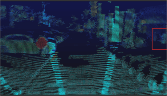
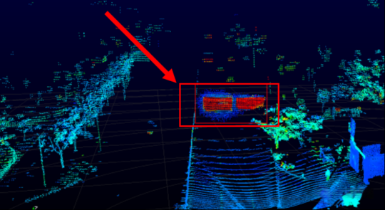
Generally speaking, the semi-solid-state LiDAR has the characteristic of being dense in the middle and sparse on both sides due to its scanning method. In addition, the semi-solid-state LiDAR has a weak recognition capability when facing low-reflectivity objects.
A technical expert from an L4 autonomous driving solution provider said: “Taking the detection of wire mesh as an example, whether it is rotary or prism, or MEMS, semi-solid state LiDARs generally have 5-6 laser emitters, which divide the laser points into spectrums through the scanning mirror. This scanning method reduces the energy of the laser point cloud after division, making it difficult to detect wire mesh or causing a large area of missing information.”
The main strategy to solve the above problems is to increase the point cloud density of the area of interest. For example, some semi-solid state LiDAR products adopt adjustable angular resolution to turn the advantage of long-distance vision of LiDAR into an advantage in angular resolution. According to different scene requirements, the perception system of autonomous driving can directly set the point cloud density of LiDAR in the area of interest based on scene needs.
Engineering level problems and solutions
2.1 Problems and solutions caused by installation methods
Under the premise of fixed hardware performance, the point cloud processing effect may be related to the installation position and corresponding angle of LiDAR. Incorrect installation may cause the point cloud to fail to cover the important perception areas.
An expert from a LiDAR manufacturer listed three incorrect LiDAR installation methods that may affect the point cloud effects: “The first type is non-forward installation. For example, some application scenarios may install LiDAR upside down, which will affect the internal structure of LiDAR. Assuming that there is a spring inside the LiDAR, when it is installed and used correctly, the spring is compressed, but when it is installed and used upside down, the spring will be pulled up, which will affect the internal components of LiDAR.
“The second type is that LiDAR is installed at too high an angle in the vertical direction. Generally, LiDAR is installed horizontally in the vertical direction, and the angle in the horizontal direction can be determined according to specific needs. However, sometimes the LiDAR on the vehicle is installed at too high an angle in the vertical direction. For example, the LiDAR is installed too upward or too downward in the vertical direction, causing the point cloud to not fully cover the important perception area.
“The third type is installation at too low a position. If LiDAR is installed at a low position, the angle between the laser beam and the ground will decrease, which will cause the laser beam to reflect back with weaker energy, which is not conducive to actual detection. Therefore, LiDAR is generally installed at a high position.”
Of course, how LiDAR is installed still depends on what specific function needs to be achieved.The perception algorithm engineer of a certain automobile manufacturer said, “Configuring sensors without focusing on functionality is not a legitimate way to develop a product. For Robotaxis, a lidar needs to be installed on the roof to achieve 360° horizontal FOV. If the lidar is used to detect blind spots, it needs to be installed on the front, rear, left and right sides of the vehicle to enable lane changing while driving. If the lidar is used for the pilot function (high-speed navigation assistance), it is usually installed at the front of the roof. If the lidar is used for intersections, it needs to be installed on each of the front sides of the vehicle.”
2.2 Problems and Solutions Caused by FOV Design
Even if the installation is correct, if there are shortcomings in FOV design, the lidar will still have perceptual blind spots. So, how much horizontal or vertical FOV should be designed for the lidar to be suitable? In the horizontal direction, how should the FOV of multiple lidars be stitched together to effectively cover the blind spots?
Table: FOV of Some Lidar Products
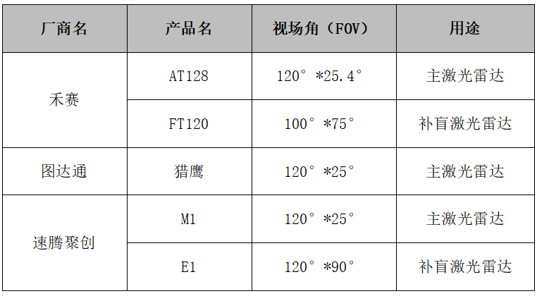
First of all, in terms of horizontal FOV, most applications hope that the lidar’s horizontal FOV can cover without dead angles. However, considering the cost, the specific horizontal FOV design needs to be determined based on the lidar’s function.
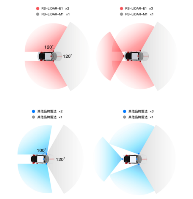
The perception algorithm engineer of a certain automobile manufacturer said, “For urban or highway scenarios, a lidar with a horizontal FOV of 120 degrees is sufficient. For parking scenarios, the lidar’s horizontal FOV needs to reach 360 degrees.”
In urban or highway scenarios, the main function of the currently produced vehicles is to assist driving, and the main function of the lidar is to recognize and detect forward targets, so a single lidar with a horizontal FOV of 120° can be used. Some car manufacturers use two main lidar solutions to increase the coverage area of the lidar in front of the vehicle, achieving an FOV of around 180 degrees. Other car manufacturers use a solution of one forward main radar and two side blind-spot lidars (installed on the left and right sides of the vehicle), enabling the entire horizontal FOV to reach over 320 degrees.In the parking scenario, in order to achieve the AVP function of high-level autonomous driving, the deployment of lidar needs to use a horizontal FOV of 360 degrees (1 forward main lidar + 2 side auxiliary lidars + 1 rear auxiliary lidar), which can cover the point cloud of the entire scene.
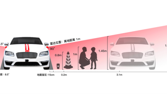
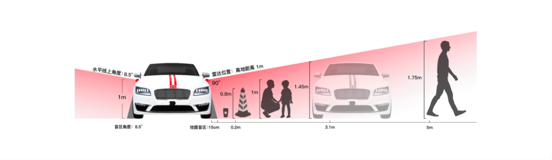
Secondly, in terms of vertical FOV, the main lidar needs to minimize the vertical FOV to obtain more forward information and increase the number of point clouds in front of the car and return more energy, so the vertical FOV is generally only 25 degrees. On the other hand, the auxiliary lidars need a larger vertical FOV in order to see the environment around the car, which can reach nearly 90 degrees horizontally.
An perception algorithm engineer from a certain automaker says, “To deal with targets such as children and pets that are small in size and are prone to running around, the vertical FOV of auxiliary lidars needs to be larger so that they can scan targets at close range to the greatest extent possible and ensure that the point clouds scanned on the targets are more complete.”
2.3 The Problem and Countermeasures of Overlapping Areas of Multiple Lidars
When designing the deployment scheme of multiple lidars, the horizontal FOV of multiple lidars often needs to have overlapping areas instead of being perfectly seamlessly stitched together. The reasons for designing point cloud overlapping areas are:
Firstly, the official FOV marked by lidar products is an ideal state, and the horizontal FOV of the products may not reach the ideal level when they are actually applied.Dr. Xu Jian, the leader of the Tudalex algorithm, said: “Although the horizontal field of view of the LiDAR product is specified, the quality of the point cloud at the edge of the horizontal field of view is likely to degrade. It is better to have some overlap when stitching the point cloud.”
Secondly, the overlap of multiple LiDARs mainly covers the blind spots of the vehicle. For example, the scheme of one main LiDAR plus two supplemental LiDARs, the overlapping area is mainly distributed at the front end of the vehicle, which increases the data information of the point cloud and improves the perception ability of the blind spot of the model. For example, the scheme of two main LiDARs in front of the vehicle can increase the redundant safety information of the perception area at the front of the vehicle.
A perception algorithm engineer of a certain vehicle manufacturer said: “If two LiDARs are simply stitched together, the perception system may have difficulty detecting a target object at the blind spot position when the target object is located in their respective edge areas. When two LiDARs have a certain overlap, at least a large part of the point cloud can cover the target object.”
Therefore, it is necessary for the perception areas of multiple LiDARs to overlap, and the overlap area can make the point cloud denser and the information redundancy higher. So, how much intersection of the point cloud overlap area is sufficient in the horizontal FOV direction?
Leon said: “From the feedback of the application party, they require a certain overlap between multiple LiDARs to ensure that the autonomous driving system does not miss any target when identifying and detecting. At the same time, they do not want the overlap area to be too large, which will cause a waste of resources.”
In other words, if the overlap area of the point cloud is small, the difficulty of point cloud registration will increase due to the sparseness of the point cloud at the edge of the scanned area of some semi-solid LiDARs. If the overlap area of the point cloud is large, it will waste the performance of the sensor hardware, making the overall horizontal FOV of multiple LiDARs too small.
After communication with experts from various fields, the author summarized the size range of the overlapping area of the point cloud under different LiDAR schemes:
-
Two forward main LiDARs scheme: The overlapping area is distributed in front of the car hood, and the degree of the overlapping area is about 20-30 degrees;
-
One main LiDAR plus two supplemental LiDARs scheme: The overlapping area is distributed on both sides of the front of the car, and the degree of the overlapping area is probably not less than 5 degrees.
Of course, the above range of overlapping areas is an ideal range, and strict testing is still needed when applied in the vehicle.
许建 said: “When deploying multiple LiDARs, technicians need to conduct a strict application test about the degree of overlap area, and not directly set a specific value. First, technicians will conduct 3D simulation testing according to the given product design index parameters. Then, they will conduct on-site testing based on simulation testing. Finally, a corresponding overlap area setting will be given.”
After determining the degree of overlap area, the next step is to solve how to use the target point cloud data of the overlap area.
The point cloud data of the overlap area does not mean that it can be used directly, and there are certain difficulties. Xu Jian said: “On the one hand, the point cloud of the overlapped area may come from two different technical routes of LiDAR. These two LiDARs not only have different parameters such as power, field of view, and angular resolution, but also have different actual usage.”
In general, due to the different technical solutions of various application parties, the handling methods for point cloud overlap areas are also different. The author has sorted out three possible solutions.
The first solution is to directly use the main LiDAR for detection and recognition.
Leon said: “For the overlap area, perception algorithm personnel can increase the reliability of recognition by supplementing the signals of multiple LiDARs, or only look at the point cloud data of the main LiDAR, after all, compared with the side-blind LiDAR, the main LiDAR has higher performance in detection accuracy, distance, etc.”
The second solution is to first use the point cloud data of the main LiDAR, and then use the point cloud data of the supplement-blind LiDAR.
An algorithm engineer of a certain OEM said: “In many cases, the point clouds of two LiDARs with different performance indicators overlap together, and it is impossible to combine the two point clouds into one point cloud for use. In many cases, the main LiDAR goes to measure it first, and then the supplement-blind LiDAR goes to measure.”
The third solution is to fuse point clouds from multiple LiDARs.
A certain technical expert from Hesai said: “In order to reduce computational consumption and improve algorithm efficiency, multi-LiDAR fusion is basically done by front-end fusion of point clouds in mainstream solutions. The front-end fusion process will transform all point clouds into the vehicle coordinate system for unified processing and solve the differences in point cloud data caused by different installation positions to the greatest extent.”
2.4 The Problem of Calibration Parameter Offset and Countermeasures
In order to better fuse the data of LiDAR and camera, autonomous driving vehicles need to calibrate the two sensors well when they leave the factory. After the perception algorithm personnel obtain their external parameters, they convert the three-dimensional information of the two sensors to a unified coordinate system for fusion positioning, mapping or perception detection.The calibrated sensor parameters are not constant. In fact, during the driving process of the vehicle, due to the continuous mechanical vibration of the vehicle, the calibration parameters between the lidar and the camera will be offset, which will affect the point cloud recognition and the fusion process of the lidar and the camera.
An algorithm engineer of a certain OEM said: “Calibration between the lidar and the camera is difficult. Although joint calibration of vehicle sensors has been done when it left the factory, the calibration relationship between them will gradually change over time. At this time, it is impossible to let the vehicle return to the factory for recalibration.”
“For mass-produced cars, it is not possible to drive them back to the factory for recalibration because they have already been sold. Autonomous vehicles can only be calibrated online. The system will recalibrate the autonomous driving system after the vehicle has driven to a specific scene, such as a scene with more line and surface features, based on the data already collected. If it is on a highway, it is difficult for autonomous vehicles to find a specific scene for recalibration and can only drive to a specific location in the city for recalibration.”
“For low-speed vehicles in segmented scenes, as most low-speed scenes are semi-closed scenes, technicians usually select an easily calibrated location in the scene, drive the car there, and then recalibrate it. Finally, if the problem cannot be solved, autonomous driving companies will send someone to the scene.”
References
【1】The Challenging Weather in Autonomous Driving
https://mp.weixin.qq.com/s/oFjHLRX2c1y2eP00TRsBjg
【2】Unveiling the “Ugliness” Hidden Under the Mask of Lidar
https://mp.weixin.qq.com/s/XbUlUTr0jIDLcrquOleG6A
【3】Solid-state E1 Arrives to Complete the Last Piece of the Puzzle of Vehicle Lidar in the New Era
https://mp.weixin.qq.com/s/-bCgsSQBH89_tnmJmQGl1w
This article is a translation by ChatGPT of a Chinese report from 42HOW. If you have any questions about it, please email bd@42how.com.