Author: Xiao Dong
Editor: Chris
Last week, I visited General Motors’ Wuhan Ultium factory.
The Wuhan Ultium factory, the second factory following the Shanghai Jinqiao Ultium factory, is currently responsible for the production of Buick Electra E5. In the future, other electric cars based on the Ultium platform, such as the Buick E4, will also be produced here. Given the Ultium platform has been launched for only over two years, it is certain that Buick’s pure electric vehicles will all come from this factory in the next five or so years.
Buick Electra E5 is not yet officially available, but the trial production cars have been taken offline. In addition to the information announced by the Ministry of Industry and Information Technology, E5 battery pack will adopt an exclusive 811 formula, and the CLTC version with front-wheel drive can achieve a range of 600 km.
Internally, the E5 battery pack has the same formula as its big brother Cadillac Lyriq. However, Lyriq uses a 12-module combination, while E5 is divided into two combinations of 10 modules and 8 modules respectively. We can also guess that E5 will have two versions: 80 kWh and 64 kWh, based on the Lyriq’s 95.7 degrees of battery capacity.
The front-wheel-drive version of E5 will use a 180 kW permanent magnet motor, while the four-wheel drive version will use a product combination of front permanent magnet motor and rear asynchronous motor, and the rear axle will use a low-power asynchronous motor.
Now, let’s get into the main topic. Buick has disassembled and displayed the battery and electric drive components and made the entire manufacturing process public. With Buick’s event, let’s take a look inside the battery and electric drive components.
What Makes Battery Safety Different?
Battery safety has always been the top priority and pain point of new energy vehicles.
To solve this problem, two aspects need to be addressed: prevention of battery fires and response measures after a fire occurs.The battery pack of the Aotengneng EV adopts NCM 811 cells from Ningde, which have higher energy density than 523 cells but slightly lower stability. Therefore, temperature control of the battery becomes the first task to solve. In the initial design of the battery, the positive electrode formula of the cells was improved by adding rare earth elements to reduce oxygen mobility and improve thermal stability.
Each cell is equipped with an exhaust channel (the blue area on top of the cell in the figure below). As shown in the figure, a layer of mica sheet is applied to cover the cells, which plays a role in insulation and thermal insulation to prevent multiple modules from losing control at the same time due to arcing caused by thermal runaway. The mica sheet also has window designs at the exhaust channel of the cells to facilitate heat dissipation in the event of thermal runaway.
In addition to anti-arcing design, silica gel is laid between the cells to reduce heat transfer. A separate liquid cooling plate is installed under each module to ensure that the heat dissipation capacity of each module can be maintained consistently.
By improving the positive electrode formula, laying silica gel, and installing independent liquid cooling plates, the probability of thermal runaway can be effectively reduced. If thermal runaway occurs, how will this battery pack respond? The anti-arcing design mentioned earlier can effectively reduce simultaneous loss of control of the multiple modules. After a single module experiences thermal runaway, the explosion-proof valve will automatically open to quickly release high-temperature gas and avoid harming others.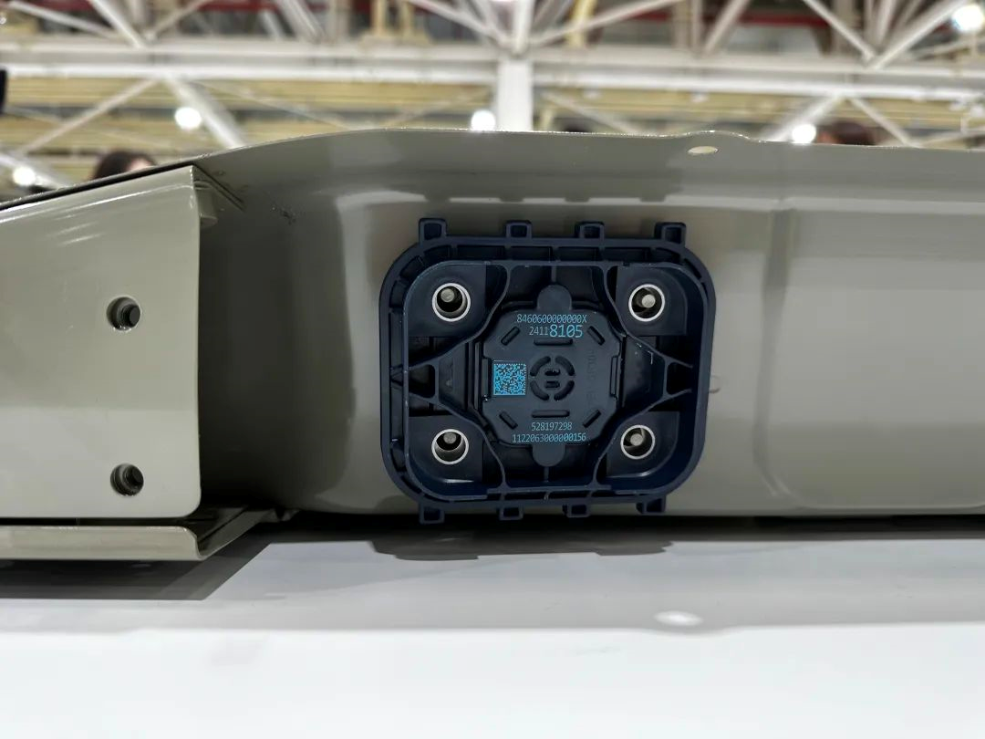
At the same time, a fireproof blanket made of high-silicon oxygen cloth, aerogel (inside), and fiberglass cloth is used on the cover of the battery pack to ensure that the heat generated by the battery pack will not be transmitted to the cabin. The heat is discharged from the bottom explosion-proof valve to ensure the safety of the passenger cabin.
After talking about the interior, let’s talk about the battery shell. In addition to forming a cross shape with multiple 1500 MPA high-strength steel crossbeams to enhance the overall strength, the upper cover assembly also uses 1500 MPA side protection beams, and the tray assembly uses 1000 MPA bottom protection to reduce damage to the battery in the event of a collision.

These all refer to “hard” protection for the battery. Now let’s talk about “soft” protection.
The combination of the car and the cloud conducts 24-hour monitoring of the E5 battery pack, with a detection frequency of 10 times per second. If there is a risk of thermal runaway, the module or surrounding module’s CMU (wireless communication unit) will wake up the battery management module for rapid cooling to detect cell abnormalities as early as possible and prevent them.
The combination of car and cloud has been used in more and more models for nearly two years, but no automaker has disclosed specific data. What is the effect? There is a question mark here.
The multi-layer protection makes the battery pack on the Aulton platform achieve very good laboratory results, such as the extrusion test being three times the national standard requirement, the 2-meter high drop test, and the battery pack not generating open flames, explosions, thermal runaway, etc., surpassing many national safety tests. During the factory visit, I also felt that Aulton was keeping strict requirements for the encapsulation, testing, and execution of its battery pack.
The high-strength shell, module, customized cells, and multiple battery thermal management technologies enabled Aulton’s battery pack to achieve excellent safety results. However, the other side of the scale is the energy density of this battery pack.Even with an 811 battery, the structure of the battery pack for Oter Energy, which consists of battery cells, modules, and packs, results in a relatively low energy density, only achieving 160 Wh/kg, which is basically the same as 523 battery cells under the current CTP structure. The recently released IM LS7, which adopts 6-series single crystal high-nickel battery cells, boasts an energy density of 195 Wh/kg.
The low energy density leads to an increase in the overall weight of the vehicle. Even with the wBMS (Wireless Battery Management System), the weight of the single battery pack for the Cadillac Lyriq still reaches 600 kg. The battery pack for HUMMER EV alone, with a capacity of 212 kWh, weighs as much as 1.3 tons.
At the same time, the height of the Oter Energy battery pack is as high as 150 mm, making it challenging in terms of vehicle height for sedans under the Oter Energy platform.
When it comes to the quality of battery packs, each automaker has a different interpretation. Based on their history, brand identity, and user demand, among other considerations, they seek to strike a balance.
A Look at the Motor
On the other side of the battery factory is the production base of the powertrain.
The 1.5T engines for Buick Regal and Buick Encore are produced here. However, today’s protagonist is still the 180 kW permanent magnet motor on the front axle of Buick E5. It was my first time observing the assembly and disassembly of an electric drive at close range. So, how is the electric drive composed and how does it work?
Firstly, the motor stator. Over the past two years, flat wire motors have become increasingly common. The stator component is composed of stator iron core and Hari-pin (fixed lock) winding. The stator component is a key factor in determining the performance of a motor, meaning that how much electricity the car consumes and how fast it can go are all related to the motor.Compared with the circular wire motor, the flat wire motor has higher efficiency, power density, heat dissipation capacity, and NVH performance. It is easy to understand that the winding method of the red part in the figure is obviously higher than the slot filling rate of the circular motor.
In fact, the flat wire motor was applied to the fourth generation of Toyota Prius as early as 2015, but it only began to popularize in China from 2020. Many brands such as Landtour, NIO, and Jinkr all use flat wire motors. At present, the 8-layer hairpin winding motor has gradually become mainstream. Therefore, the efficiency of most of the permanent magnet motors has reached 96%-97%, and the efficiency of the permanent magnet motor on the U8 has reached 97.7%.
Of course, the stator core also bears the responsibility of improving NVH and heat conduction efficiency to a certain extent.
Secondly, the motor rotor, as the name suggests, is the part that can rotate quickly when the motor is working. The figure below shows the rotor of a permanent magnet. The stator and rotor drive the gears to complete the working state of the motor.
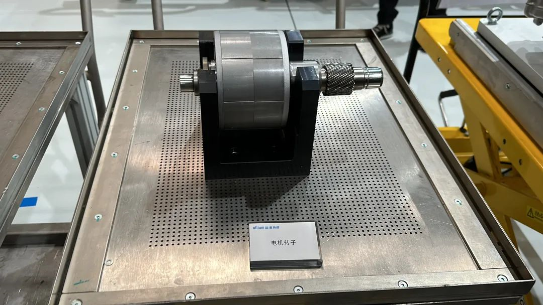
The above is only the simple logic of motor operation. It is impossible to directly place the rotor and stator on the car. At this time, a housing is needed to carry them. From the small holes above the housing in the figure, it can be seen that these small holes are used to cool the stator. The previously more common cooling method was water cooling, but its heat dissipation efficiency was relatively low. Therefore, in some evaluation programs, some pure electric models will limit power output to dissipate heat and ensure that the permanent magnet is not demagnetized after a few sharp accelerations.

In recent years, performance-oriented pure electric models have switched to oil cooling to improve heat dissipation efficiency and ensure the anti-attenuation ability of continuous acceleration.
The above is a simple explanation of the advantages of oil-cooled flat wire motors that we often hear.
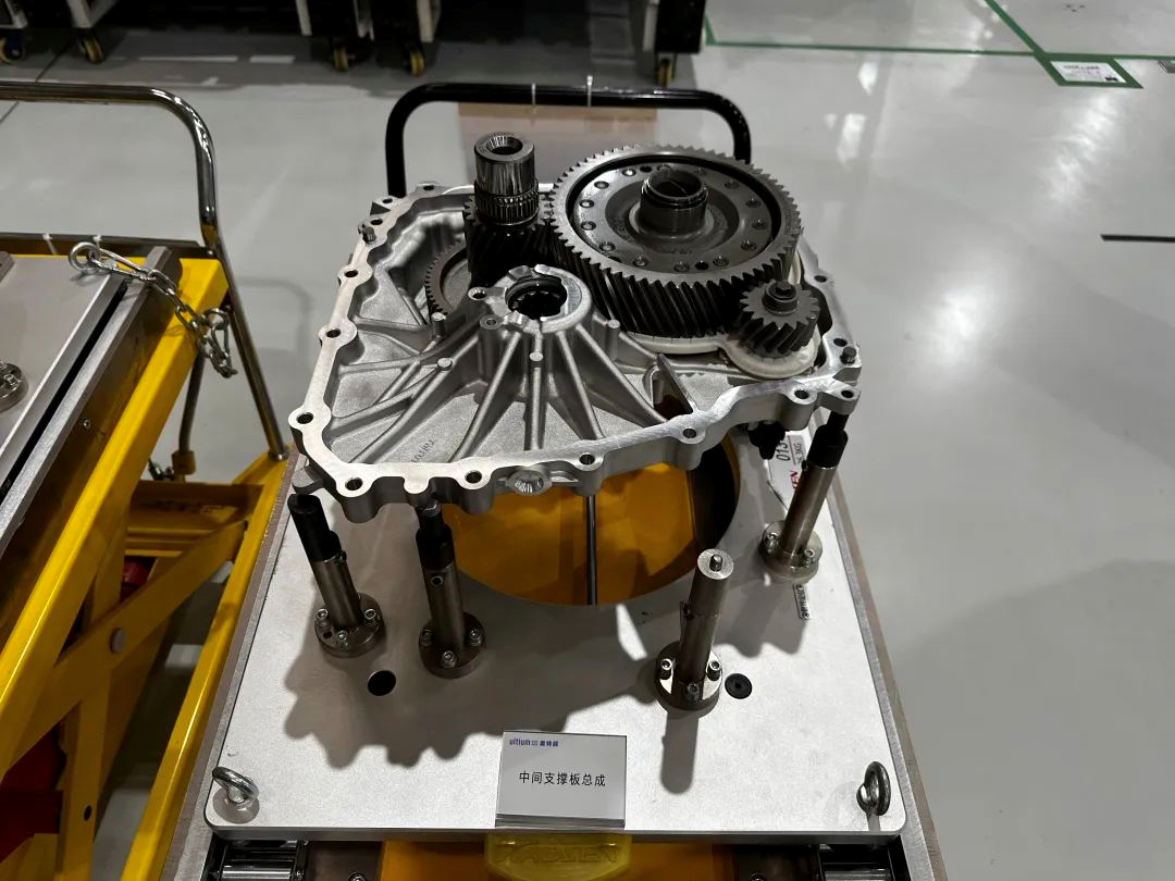
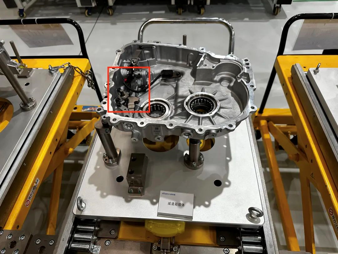
Returning to the question of how the motor drives the wheels, this requires mentioning a “key player”- the gearbox. The speed of the driving motor is basically in the range of 16,000 to 20,000 rpm. It is impossible to directly apply this speed to the wheels, which obviously cannot match the speed range of the entire vehicle, and the torque is also insufficient.
Therefore, the gearbox became an important component that matches vehicle speed through gear amplification of torque and reduced revolutions. The principle is that the small gear drives the large gear to form different gear ratios, which will not be discussed in detail here.
Apart from integrating the motor stator, rotor, and gearbox, this Altenergy 180 kW electric drive system also features a 7 or 8 in 1 drive unit design that includes motor controller, AC charging module, 12 V high and low voltage modules, etc.
In addition, the Altenergy electric drive also has a small touch in the design of the parking mechanism inside the gearbox housing, which ensures that the vehicle will not slide on a slope when parked, improving safety.
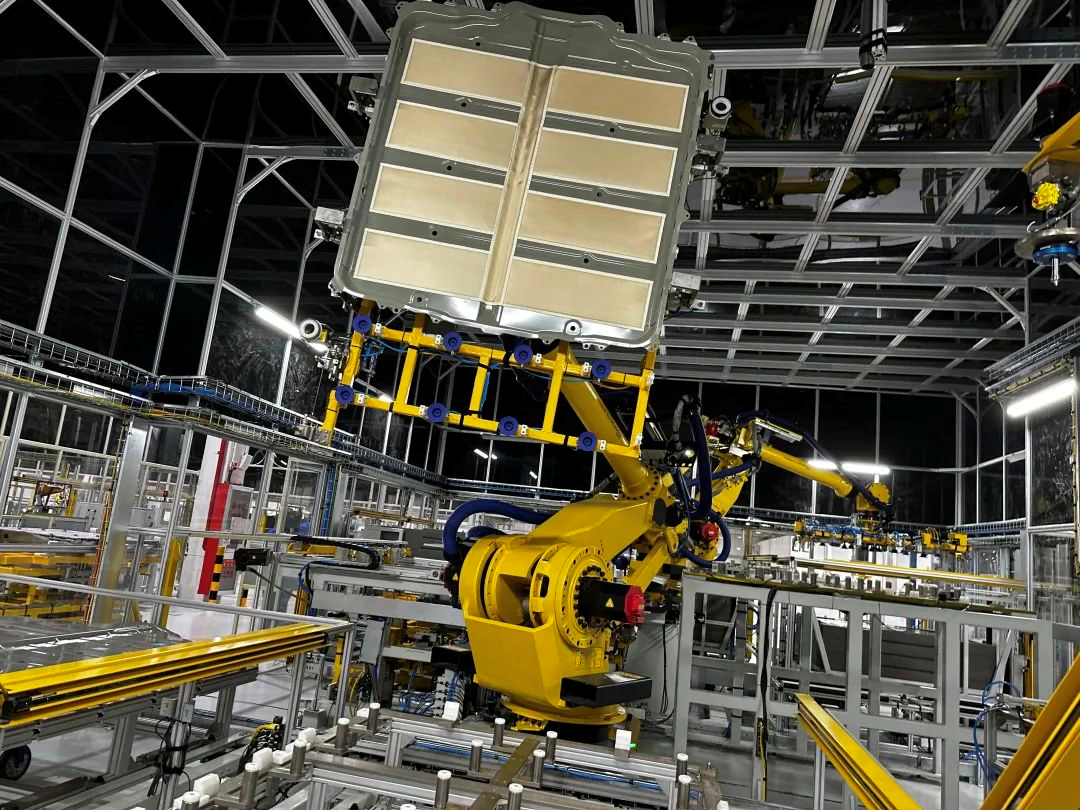
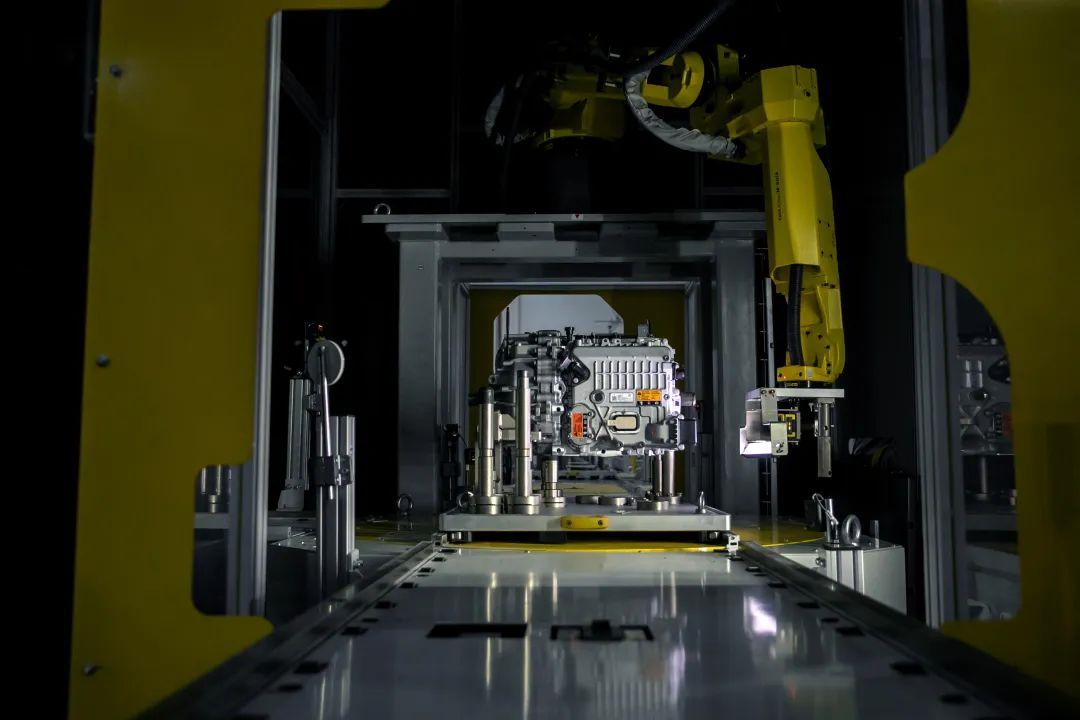
Most of the electric drive installation process is completed by robotic arms because the motor assembly accuracy needs to be controlled within 50 μm, which is about the same as the diameter of a hair. In addition to large-scale automated assembly, the electric drive also undergoes multiple performance tests, including sealing, insulation, and functionality. I was impressed by the quality inspection process conducted by a 3D visual robot.
This trip to the Altenergy factory in Wuhan was rewarding, with on-site explanations by engineers giving me a great understanding of the battery pack and electric drive’s disassembly structure, as well as how they are assembled from parts to a whole, helping me to understand some of the ingenuity of engineering design. Perhaps this is the charm of the automotive industry.
This article is a translation by ChatGPT of a Chinese report from 42HOW. If you have any questions about it, please email bd@42how.com.