The Importance of Intelligent Cockpit Storage, the Bigger the Better
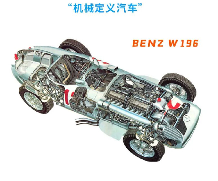
As we all know, China’s new energy vehicles are gradually moving towards the right track, and more and more users are choosing new energy vehicles with more intelligence. From the development trend in the recent 5-10 years, cars have evolved from mechanically defined cars to electronically defined cars, to the recently popular software-defined cars.
After the generalization of car hardware, the research and development environment of car software has become easier, including the software application scenario of operating system construction and application ecology construction. Just like PCs and smartphones, the differentiation of cars is mostly reflected in software, that is, software-defined cars. When Chinese new energy vehicles evolve towards intelligent vehicles, they are copying the fast replication path of intelligent smartphones in China’s manufacturing industry.
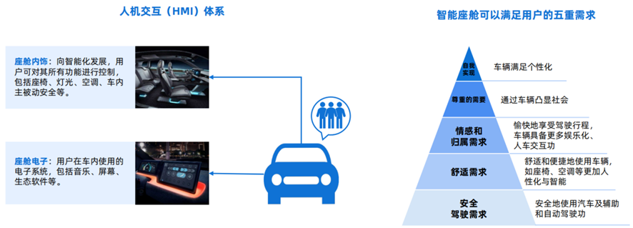
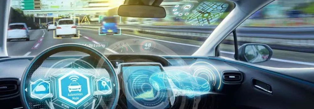
In recent years, the development of intelligent cockpits has been getting faster and faster. The entire intelligent cockpit has become a must-win battlefield for the entire host factory’s “King of Internal Circulation”. It can satisfy users’ multiple needs. Users hope that vehicles will become more intelligent like smartphones. In addition to driving comfort, more personalized settings and human-computer interaction can make users experience the emotional needs of this car.
Moreover, the competition among the host factories is increasingly homogenized, and they need to form product differentiation. The intelligent cockpit happens to be a breakthrough, and internet companies in the saturated mobile terminal market think that cars will be another intelligent terminal carrier after PCs, mobile phones, and tablets. The intelligent cockpit is the most important carrier of this carrier.
Let’s review the trend of mobile phone storage capacity:
 Before the rise of smartphones, it was basically Nokia’s feature phones that dominated the market. Take the Nokia 5230, a legendary device in 2009, with a storage capacity of only 256MB, which cannot store a high-definition video as it is today. At that time, it was still operating under the Symbian system which had almost no APP functionalities, just some basic functions like listening to music, making phone calls, and simple games.

Later on, smartphones started to emerge around 2010, such as the Apple iPhone 4 which initially had a storage capacity of 16GB-32GB, allowing for simple video communication and simple games. However, storing high-definition maps offline was not yet possible back then.
Nowadays, when you buy a new phone, who would settle for less than 64GB of storage or more? If you were using a 32GB iPhone 7, you would be tired of deleting photos and clearing caches every day. Every application consumes hundreds of MBs, and even WeChat chat records can take up to 10GB of storage.

In terms of the development of intelligent automotive cockpits (and storage requirements):
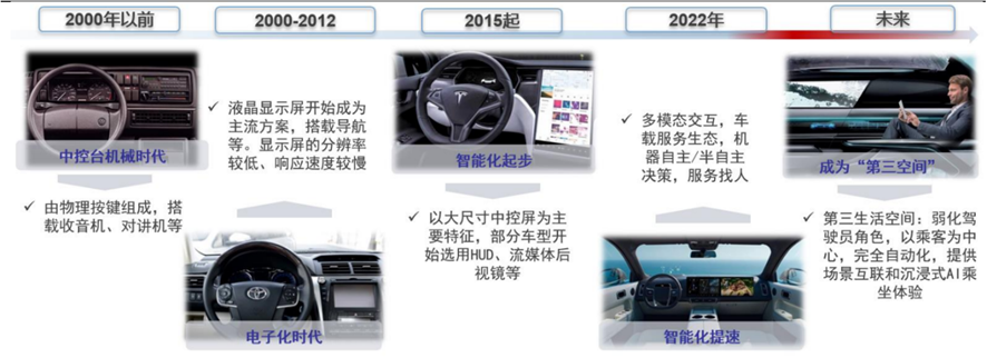
1) In the 1990s, during the mechanical stage: it only included mechanical instrument panels and in-car devices such as radios and intercoms. There were plenty of physical buttons, providing only basic information such as vehicle speed, engine speed, coolant temperature, and fuel level.The storage at this time was still mainly NOR FLASH, similar to the Nokia era of mobile phones, only simple information such as mileage and radio settings needed to be stored, and the storage demand would not be greater than 100MB.
2) 2000-2015, the Era of Digitalization: Electronic technology entered the cockpit, equipping it with small-sized central LCD displays, in-car navigation, Bluetooth, media players and other relatively simple electronic devices.
At this stage, the storage demand gradually grew, an operating system was needed that required storage space, and some map data needed to be built-in to the storage, rather than updating the map through a TF card as in the past, because the maps could now be updated in real-time through the internet. Tesla even put a web browser inside the central display screen at this stage. There was not much human-machine interaction inside the car, and there were not many APPs to use on the car, so the storage capacity at this stage was basically around 16GB.
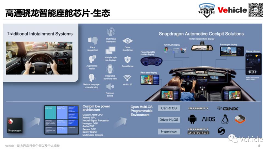
3) Since 2015, the Era of Smart Cars is approaching: The opening of the smart cockpit era was marked by the appearance of the large-sized central control screen. Consumer electronics technology entered the automotive field. LCD instruments, central control screens, heads-up displays, visual perception, voice interaction, and other functions are integrated and installed in the cockpit through domain controllers. They can provide more comfortable and intelligent driving and riding experiences according to the preferences, habits, and needs of the driver and passengers.
At this point, we come to a time similar to the era of smart phone- “component stacking” in smart cars. The industry generally describes smart cars as intelligent mobile phones with four wheels. The main reason is that after the standardization of automotive hardware, the design of the hardware structure will basically be fixed, such as the straight-board design sandwiched by the front and back covers, as the iPhone smart phone had set the wind direction of the industry back then. The differentiation for smart cars would mainly be shown through system software, electronic component configuration, and new materials application, which is collectively known as “component stacking.”
Let’s first take a look at the requirements for eMMC capacity of common LCD instruments. The figure below is a project that uses a 12.3-inch full LCD instrument platform based on the i.MX6DL. At this time, it can be seen that the capacity requirement for eMMC is relatively small, only 533MB, and the largest resource is UI picture resources. Because many cars require multiple sets of UI interfaces, such as when switching to the sports mode, the UI interface is more dazzling, while switching to the economy mode displays a more straightforward UI, which can give users a better experience, so the storage size of the instrument is mainly for UI pictures.# Translation
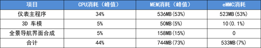
As shown in the picture above, the eMMC capacity requirement is 533MB. In fact, 4G eMMC is more than sufficient for this purpose. So, why do many automakers choose 8G eMMC? Mainly because the small capacity 4G eMMC is basically obsolete now, only Magnext and SanDisk have eMMC chips with small capacity that meet automotive industry standards, and their prices are the same as 8G eMMC. Besides, the delivery time is not as good as that of 8G eMMC. With 93% design margin, the extra capacity can be wasted since the price and delivery time are relatively stable.
Now let’s look at the capacity requirements of eMMC for central control navigation hosts. For traditional navigation hosts without online maps, 8G eMMC is sufficient, mainly because offline maps occupy the most space.
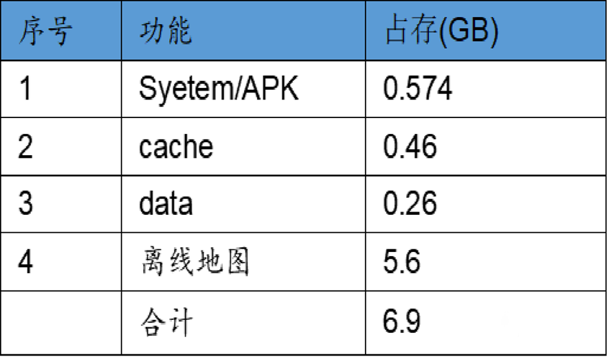
From the data, the largest part is offline map. If it is high-definition map data, this part is close to 10GB. If some applications, such as Himalaya and Qingti FM, are installed, this part also needs to reserve space for customers to download data; otherwise, users cannot download and cache locally after installing this app, but only listen online, which is not a good experience. Therefore, the eMMC capacity of the central control navigation host under normal conditions is generally 32G.
Gradually Starting Internal Control “Domain Controller”
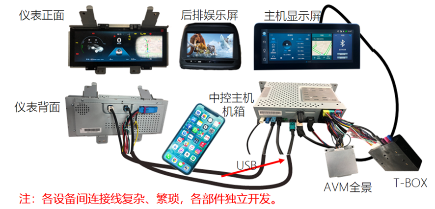
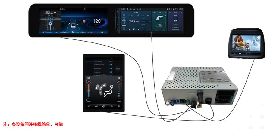
The original cabin controllers were basically separated. The navigation host was from one manufacturer, the LCD instrument was from another, and there was also one AVM panoramic view and TBOX. The wiring connection here is very complex, and the coordination and testing between different suppliers is also very complicated.
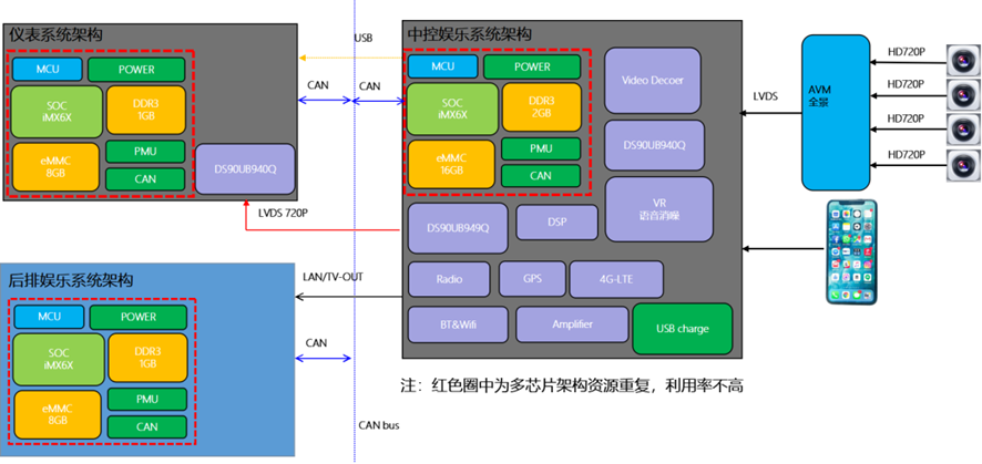 The multiple-chip solution of IMX6 is shown in the figure below. The LCD instrument, central control navigation, and rear entertainment all use the IMX6 minimum system. Therefore, the content inside the yellow frame of the figure below is duplicated. However, if only one IMX6 is used, it cannot drive three display screens, so the utilization is not high.
Moreover, the use of domain controllers for wiring changes is now simpler and allows for centralized resource development. One domain controller can replace many different devices.
And the most inward-looking thing in this process is the domain controller. At this time, the “stacking” of the smart cockpit is more about the large-scale use of domain controllers. A single chip can drive multiple devices such as the central control navigation, LCD instrument, HUD, driving recorder, TBOX, and rear headrest display, etc. At this time, the storage capacity requirements become particularly important. It is necessary to meet the storage capacity requirements of the original components and, furthermore, to include many human-machine interaction requirements, which increase the storage capacity demand even further.
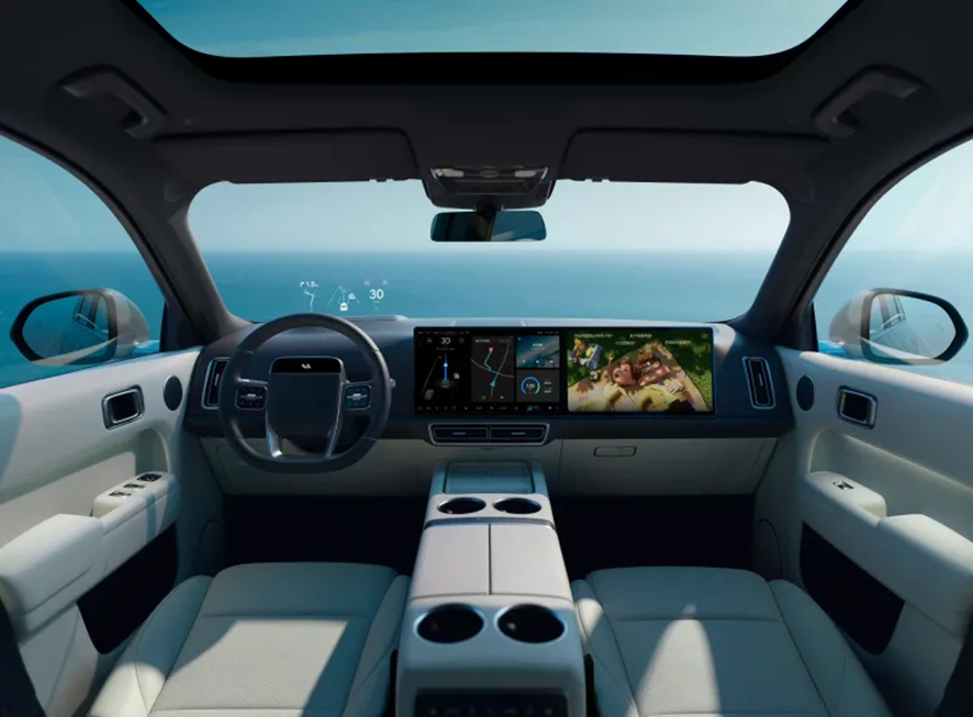
The smart cockpit of the ideal L9 is shown in the figure below. The official promotion states: The ideal L9 is equipped with two Qualcomm Snapdragon 8155 chips as standard, with a combined 24GB of memory and 256GB of high-speed storage capacity, to form a powerful computing platform.
The next-generation smart cockpit upgraded from the 8155 computing platform is equipped with a 7nm process 8-core CPU, 16G of memory, and 128G of storage space.
The XPeng P7 is equipped with the Qualcomm Xiaolong 820A, the previous generation of domain controller chips, and has a storage capacity of 8+128GB. This storage capacity is mainly to allow users to load more apps and support small program expansion, demonstrating strong practicality and entertainment.Translation:
Cars are equipped with a comprehensive visual sensor configuration, including various RGB image data, surround ray tracing data, depth of field information data, etc. They have natural advantages in AR/VR/MR image generation and production. Once their visual processing capabilities are developed, they can be combined with high-definition display screens and AR-HUD virtual display devices of intelligent cars to form the most playable intelligent terminals. Whether it is on the end or in the cloud, massive storage space is necessary.
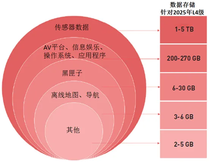
It can be seen that the storage capacity demand at this stage has developed from 64G-512G. With human-computer interaction, high-definition video content storage requirements, and the different sizes of domain control fusion, the storage capacity is gradually increasing.
Conclusion:
In fact, all information-based intelligent products are as intelligent as the intellectual level in the biological world. The most basic indicator that determines the level of intelligence is the size of brain capacity. By analogy, for intelligent products, their level of intelligence is also closely related to the computational power of the chip.
In this wave of intelligent cockpit trend, the size of the storage chip is crucial, which initially relied on the breakthrough of storage space. Only when the product’s storage space is sufficient can larger system software and application software be loaded and more data stored for production and services.
Storage Chip Requirements for Intelligent Cockpits

Since everyone knows that the larger the storage capacity, the better it is. Is it possible to replace the car’s memory chip directly with a larger capacity chip, like upgrading the memory of a phone? As the technology for upgrading phone memory is already so mature, can we take a step closer to upgrading car’s domain control storage chips?

Guys, this cannot be done directly. Although they are storage chips, the difference between the chips used in intelligent cockpits and ordinary consumer-grade storage chips is really not a little bit. Let’s take a closer look below.### 2.1. Requirements for Safety and Reliability
Let’s take Tesla as an example. Due to a memory issue, Tesla recalled about 135,000 vehicles, including Model S produced from 2012 to 2018, and Model X produced from 2016 to 2018. Tesla stated that when the 8GB eMMC memory reaches the end of its life, the corresponding controller will malfunction, causing functions such as the rear view on the screen, defrosting setting, and turn signal adjustment to not work properly. This problem typically occurs after five to six years of use. Tesla’s solution is to replace the 8GB eMMC memory with a free 64GB eMMC memory.
Storage chips for intelligent cockpit domain control must meet automotive-grade requirements
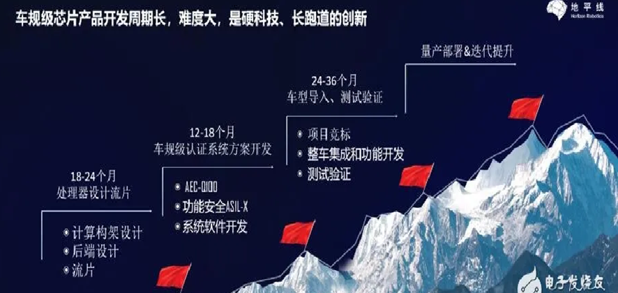
As a durable consumer product, cars require a very long supply cycle, which is different from the consumer electronics market. Due to strict standards in the supply chain and significant challenges in design and production for onboard storage, car-grade chip design is long. The storage chip for domain control stores critical vehicle control information, such as the example of Tesla stated above. Therefore, a high level of security is required to protect the application for storage of important information.
Firstly, the running conditions at high temperatures must be guaranteed. Ordinary consumer electronics products can operate normally between -10°C and 50°C. Due to the significant changes in temperature of the external environment while driving, such as the area around the rearview mirror, the temperature can reach around 90-100 degrees Fahrenheit after prolonged exposure to sunlight, which places high demands on the wide temperature control performance of the storage device. There are also slight differences in storage requirements for different locations. If it is simply an entertainment product and does not involve safety-related application data, the requirement is between -40°C and 85°C. If it is a storage chip for intelligent cockpit domain control, it must meet the temperature design requirements of at least -40°C to 105°C to ensure that storage performance can be stable within a wide temperature range in both extremely low and high temperature environments, with a failure rate of “0”.Reliability and integrity requirements for signals:
In many driving environments, there are often environmental interferences such as electromagnetic waves, which can also have a significant impact on the reliability of data. Therefore, a lot of work will be done in the design to improve the anti-interference performance of the memory. In addition, in parts related to the overall driving safety of the vehicle, compared to consumer products, vehicle-mounted memory has also increased significantly in terms of response speed, anti-vibration, reliability, error correction mechanism, debug mechanism, traceability, and data storage stability.
Not all milk is called Tetra Pak, and not all memory chips are automotive-grade memory chips. Chips from design to on-board testing and validation, and finally achieving mass production generally require at least 4-5 years of validation and should not be easily replaced.
Storage capacity requirements for intelligent cabin domain control:
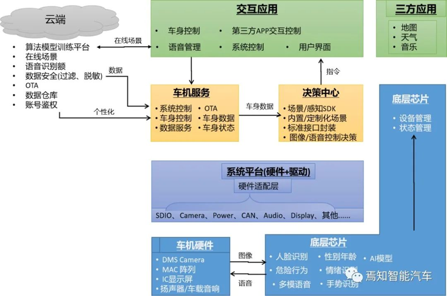
The above figure is a framework of an intelligent cabin domain controller.
The car’s hardware mainly consists of original sensing or responsive components used to receive facial or hand information of the driver input from the DMS camera and passenger information input from OMS. At the same time, it also receives relevant voice information entered by passengers in the car, as well as car audio, display, and other hardware units.
It can be seen that the intelligent cabin domain control requires very large computing power and storage to process a lot of tasks, including processing various information such as human-computer interaction, voice, face, gesture, etc.
In addition, there are requirements for displaying information such as navigation control, LCD instruments, HUD, and compatibility with third-party software applications, including weather, maps, storage of system software, management of car permissions, processing of car OTA upgrades, and other requirements for storage chips have been mentioned earlier, besides the demand for large space, there are other requirements for performance.
2.2. Fast reading speed is required
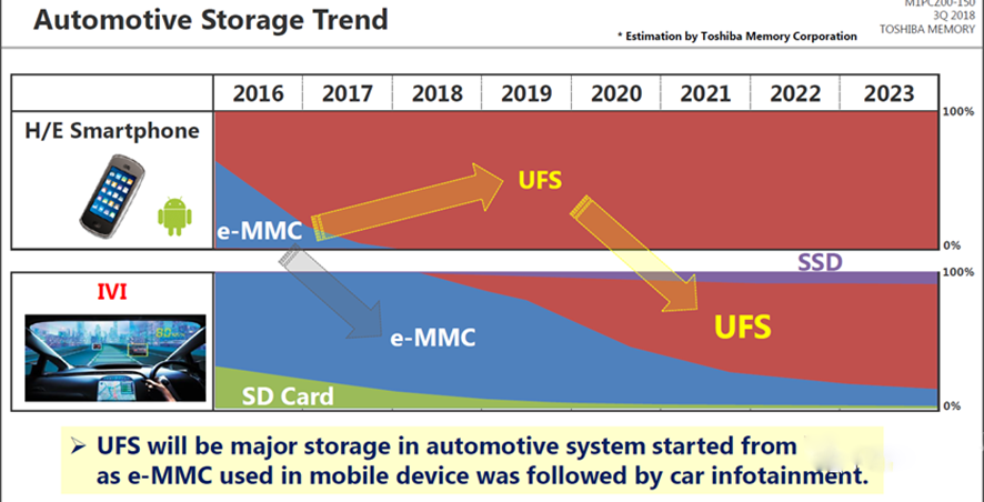
Whether in terms of technology or capacity, car navigation basically follows the development trend of mobile phones. Initially, the map of car navigation was stored using an external SD card. When the map needs to be updated, you can directly remove the SD card and go to the 4S shop for the latest map update, and it requires annual fees.Nowadays, the interfaces of mobile phones have changed from eMMC to UFS, and the interfaces of smart cockpit storage chips will also change from eMMC to UFS. So, let’s take a look at why this trend is happening.
The figure below shows the differences between the UFS interface and the eMMC interface. Both have a NAND flash kernel, but they use different control interfaces and protocols. The maximum communication speed of the eMMC interface is 400MB/s, while the UFS interface can reach a maximum communication speed of 1160MB/s.
The faster the speed, the greater the advantages. For example, think about how liquid crystal instruments need to output the interface to users as quickly as possible when they start up. Currently, Cypress’s platform can achieve a start-up time of 0.7 seconds, and the central control navigation system needs to output the reversing image to users within 1.5 seconds after the user starts the engine. Therefore, in addition to optimizing software strategy, the most important thing is to read data from the software quickly.
As can be seen from the figure below, UF2.1 has a communication speed of 850MB/s, which is more than 10 times faster than the speed of QSPI NOR FLASH at 54MB/s. At this speed, boot zone data of 64MB can be loaded in only 115ms, or 0.1s. By contrast, when using NOR FLASH, it takes 1185ms, or 1.1s, which is an extremely slow experience. Such an improvement is not only noticeable in start-up speed, but also when storing files or audio and video data. For example, if a large video is recorded and cannot be stored due to half-day loading time, this would greatly impact the user experience.In terms of data storage interfaces, the communication interface in the vehicle industry is developing towards faster interface protocols. Currently, the mainstream vehicle-mounted storage uses interface protocols such as eMMC5.1 and UFS2.1.
Currently, in the field of automotive front-loading market, the largest application is e.MMC, which is mainly used in TBox network and ADAS. Some mid-to-low-end car entertainment systems also use 8-32GB e.MMC.
Therefore, to meet the demand for fast read and write speeds, the storage in the cabin area must at least meet UFS2.1.
2.3. Demands for Flexibly Configurable SLC Storage
In the 5G mobile network, intelligent vehicles also have a memory-consuming device, which is the event recording device. In the past, cars were equipped with at most one driving recorder, which could record some simple traffic evidence videos. In many cases before, TF cards were inserted and data was stored in them.
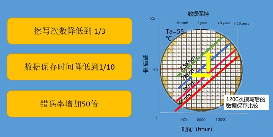
TF cards of different qualities have different erasing speeds, and often vibrate. This leads to poor contact, which can cause card damage. After long erasure times, the writing speed of the card will decrease significantly. Often, a TF card should be replaced after about half a year, otherwise it will be damaged. The figure below shows the comparison between data after 1200 erasures and data at the beginning. The erasure life is reduced by 30%, the error rate increases by 50 times, and the writing speed decreases by 90%. Basically, it is on the verge of being scrapped.
As we all know, if the content stored in the driving recorder of a car is basically about a week, because the storage card is overwritten in a covering manner. For example, a 16G TF card will gradually overwrite the previous content after the video storage is full 16G. So, if you want to see a month of video data one day, sorry, it has been overwritten.
In order to improve the embarrassing experience of users replacing TF cards frequently due to poor contact after self-matching cards for about a year, many car manufacturers have gradually begun to use built-in UFS storage for data storage.First of all, let’s define a concept. EMMC is made up of NAND FLASH, so the SLC, MLC, and TLC of NAND FLASH also exist in EMMC, and there will be the problem of erase cycle limit. The normal SLC can be erased 60,000 times, but its disadvantage is that the storage capacity is low and the larger capacity ones are very expensive. Currently, the main format of large-capacity EMMC chips is still MLC.
Taking recording high-definition videos in 1080P as an example, the data volume of a 1080P60 video in one second is: size = 2200 X 1125 X 60 = 148.5M, and the format of the video is RGB888, while the signal from the camera is basically YUV4:2:2. At this point, the data volume of 1S is 100M, and the size of a 1-minute video is 100MB * 60S = 6GB. The original data of a 1-hour-long video would be 360GB.
At this point, the data recorded in EMMC is the compressed video data. The compression format is generally H.264. The compression ratio is 60:1, so the storage size of an hour will also be 6GB.
If we allocate a 32GB capacity for the driving recorder to record, it is equivalent to being able to record about 5 hours of video before it needs to be overwritten. For 24 hours a day, it can only be overwritten about 4 times. According to an erase cycle limit of 3000 times, it can only meet a lifespan of 750 days, which is far less than the required 10 years of the car manufacturer.
At this point, we can configure the 32GB MLC storage space as 16GB SLC. Although the storage space is halved to only 16GB, the number of erase cycles supported becomes 60,000 times, which can meet a lifespan of about 17.86 years.
Because the intelligent cabin has different storage requirements and needs to support large data reading and writing storage, such as driving recorders, and high demands for the lifespan, it is necessary to support flexible SLC configuration requirements.### 2.4. Supported Dynamic Wear Leveling Technology
Due to the limited erase cycles of flash memory, frequently modified data can quickly exhaust the lifespan of corresponding blocks, making the entire disk unusable. Thus, there is a need for technology that can evenly distribute the erase cycles of these blocks, thereby extending their lifespan.
First, let’s review several related basic concepts:
Since flash memory cannot overwrite data, modifying existing data requires erasing the original data and then writing new data. Frequently modified data is called “hot data”, while data that is written once and barely modified thereafter is called “cold data”.
Blocks with relatively low erase cycles are young and strong, so they are called Young Blocks. The opposite of Young Blocks are Old Blocks, which have been erased many times and have only a few erase cycles left.
Since flash memory is expensive and its erase cycles are so limited, how will we get it done? Thus, Wear Leveling technology was proposed to extend the lifespan of flash memory through wear balance.
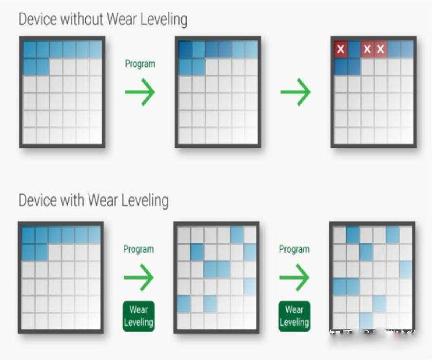
Without wear leveling, some blocks are likely to be frequently erased, eventually rendering them unusable and reducing the lifespan of the flash memory. Wear Leveling technology spreads erase operations evenly across all blocks to prevent some blocks from exhausting their erase cycles prematurely.
Wear Leveling technology is divided into dynamic and static algorithms, and local and global domains:
Dynamic Wear Leveling is mainly used in the automotive industry.
When overwriting data, new data is written to a free page, while old data is marked as invalid and waits for garbage collection to erase it.
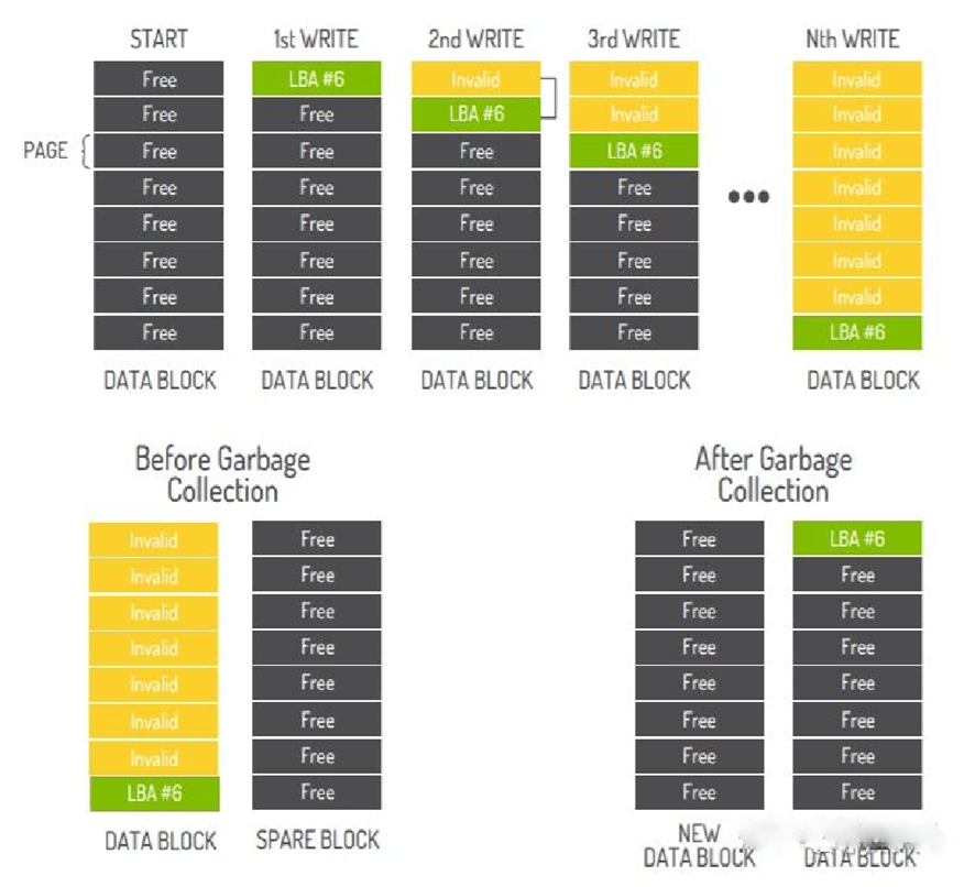
From the above picture, it can be seen that the 2nd WRITE changes the data of LBA#6, which is written to the newly allocated page rather than being modified directly on the original page. The 3rd WRITE works the same way, and by the Nth WRITE, the data has been modified N times, but garbage collection has not yet occurred, so there are many invalid pages.“`markdown
Comparing the left and right graphs of garbage collection in the above picture, it can be seen that the garbage collection has erased all Invalid pages, and the data LBA#6 has also been moved to a new block. This is because, as mentioned at the beginning, the minimum unit of flash erasure is block, so when there is user data in a block, it needs to be migrated.
Drawback: One obvious drawback of dynamic wear leveling is that when a piece of data is cold data and has not been modified for a long time, the number of erasures it occupies is very low, but it cannot be used for wear leveling.
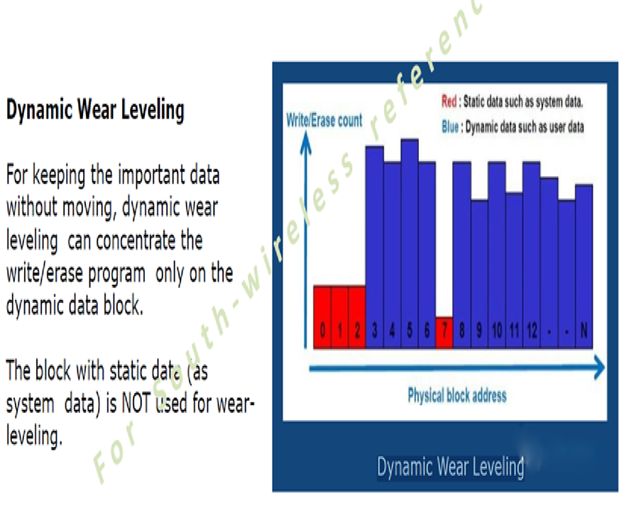
From the above figure, it can be seen that the red part is the data of the system area. It should be noted that the data of the system OS area is not used for wear leveling. Only the data of the user-used area can be used for dynamic wear leveling.
2.4. Stability of SMT Burn-in Data
This burning process is very painful for many manufacturers using EMMC. Some are pre-burnt in advance by a burner, and after SMT, it is found that some parts are not booted in the DIP assembly process. This is very painful and requires a lot of troubleshooting.
Finally, it was determined that the software was lost, and at this time, the software needed to be re-burnt (if it was a built-in high-definition map of 10G), often upgraded through USB, and a single burning time was at least 15 minutes.
This greatly affects the production efficiency of the production line. If it is not pre-burned and directly burned in the back end, it will not be possible to perform the corresponding functional check after SMT. At the same time, a large number of burn-in fixtures are also required, which may also affect the entire production pace. So why does software dropouts occur?
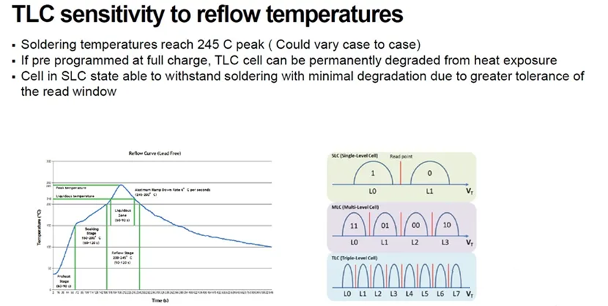
As mentioned earlier, there is a difference between TLC, MLC, and SLC process. For TLC process, for example, 8 levels need to be separated in 0-3.3V. At this time, during the 245℃ reflow soldering of SMT, the voltage level is very likely to undergo slight discharge inside, and this may modify the voltage of L5 to L4 or other levels.
“`
And for SLC, only the difference between high and low voltage, which means it is not easy to discharge and fall in. The boundary range is farther. Therefore, the programs that are failed are mostly MLC or above eMMCs. Data flip is caused by discharging because the machine itself is not powered on and there is no charging situation. Therefore, the flipping of data bits is a mistake of changing 1 to 0.
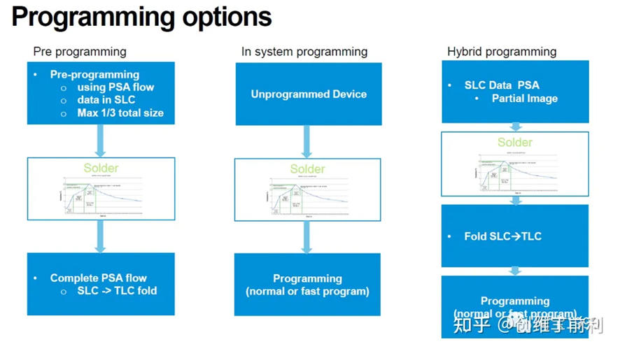
Currently, Western Digital’s automotive-grade chips support 100% pre-burning, fully ensuring the user’s worry-free use, without worrying about the risk of SMT data loss, and solving users’ worries.
Western Digital’s iNAND AT EU312 UFS fulfills the “Prince Charming” of intelligent cockpits.
3.1. High capacity (storage capacity ranges from 16G-256GB can be selected)
Firstly, this series has different capacity configurations, which can meet the storage capacity requirements of products in different stages of intelligent cockpits.
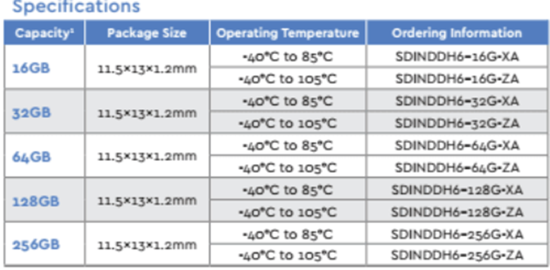
It can be seen that the storage capacity ranges from 16GB-256GB, some car models still have traditional configurations. At this time, the central control navigation can choose a configuration of 32GB. If it is already configured with Qualcomm 8155 or 8295, the storage can be selected from 128GB, or even 256GB.
3.2. High reliability
In addition to meeting the storage capacity requirements of the entire intelligent cockpit, Western Digital has also invested a lot of efforts for reliability and security.
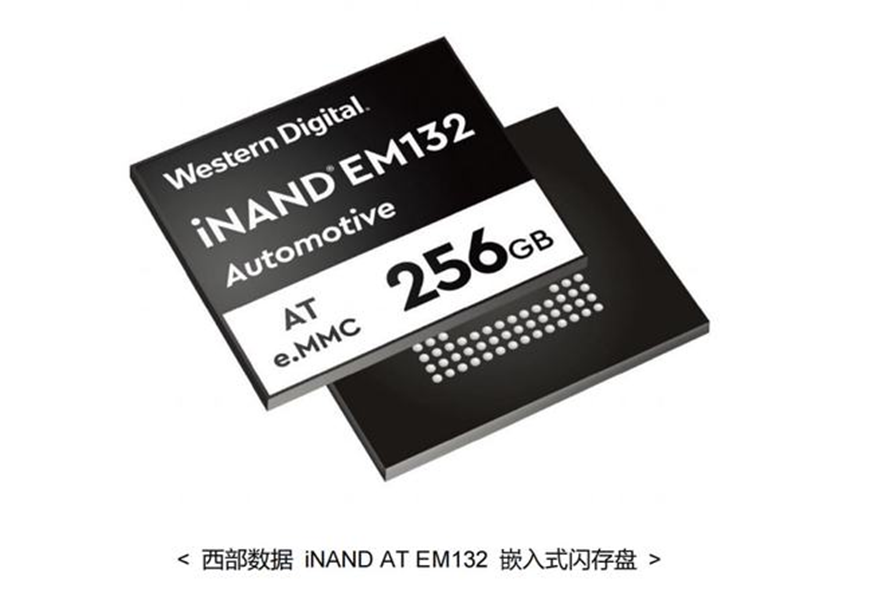
The new 256GB Western Digital iNAND AT EM132 embedded flash drive adopts 64-layer 3D NAND TLC flash memory technology, which exceeds the product lifecycle of 2D NAND to meet the changing application requirements and growing capacity demands.# iNAND AT EM132 Embedded Flash Drive Certified by IATF16949
The Western Digital iNAND AT EM132 embedded flash drive is certified by IATF16949 and compliant with AEC-Q100 standards. It also adheres to the ISO26262 NAND flash security mechanism guidelines and includes rich automotive features specifically designed for intensive automotive workloads, such as advanced operation monitoring, thermal management, automatic and manual read refresh, powerful power management, data retention that exceeds JEDEC standards, and advanced data protection and error correction technologies.
3.3. High Speed
Thanks to the optimized 3D NAND technology and fast UFS v2.1 interface, the iNAND of the EU312 EFDs provides excellent read and write performance, delivering an embedded storage solution suitable for most data-intensive automotive applications.
The write speed is up to 550 MB/s and the read speed is up to 800 MB/s, fully meeting the read and write speed requirements of today’s intelligent cockpit.
3.4. Flexible Automotive Specific Features
These include advanced running status monitors, enhanced power failure protection, fast booting, enhanced SLC LUN, and OEM-configurable boot partitions.
As the operation of automobiles takes place in very complex environments, situations arise where there is poor contact between the power supply line of the central control navigation and the 12V power supply of the vehicle body’s battery. Moreover, it is also possible to simulate a power outage of 50ms during the 7637-2 experiment of the vehicle-level standards, and a large capacitor is designed to ensure the normal operation of the entire system in case of such unexpected power outages. Therefore, each component also requires enhanced power protection to ensure the safety of stored data.
Failure risk is likely to occur when enhanced power protection is not used while saving critical data.
Optimized for a wide range of read/write intensive use cases, this feature is particularly useful in areas where data usually must be read or written, such as the area where the image of the driving recorder is saved, which is not suitable for dynamic balancing of the entire area. In such cases, these special functions are very important for the intelligent cockpit.
Choose Western Digital Storage for peace of mind in using storage chips in the intelligent cockpit.
Western Digital has over 30 years of expertise in flash development and system design. Vertical integration in the design, manufacture, assembly, testing, reliability analysis, and monitoring of flash chips supports the entire product lifecycle.In terms of in-vehicle storage, support can be expanded for PCN and EOL, as well as for providing the automotive industry-specific Production Part Approval Process (PPAP) files. The iNAND AT series is designed for high-reliability in-vehicle applications, and has very low DPPM throughout the entire manufacturing process.
This article is a translation by ChatGPT of a Chinese report from 42HOW. If you have any questions about it, please email bd@42how.com.