
Author | Pajiang
According to different brake actuators, brake-by-wire systems can be divided into electro-hydraulic brake (EHB) and electro-mechanical brake (EMB). EHB is based on traditional hydraulic brake system, using electronic components to replace some functions of mechanical components, and using brake fluid as power transmission medium, while also having hydraulic backup brake system, which is currently the mainstream technology. Based on the degree of integration, EHB can be divided into two types: Two-box and One-box.
With the expansion of the new energy vehicle market, “eBooster+ESC” has become the most mainstream Two-box solution on the market. In addition to achieving basic brake assist function and stability control function, this solution can also co-ordinate and ensure consistent pedal feel for the driver in the switch between electric and hydraulic braking while achieving energy recovery during braking. In addition, with the popularity of advanced driver assistance systems and automatic parking systems, “eBooster+ESC” also plays a role in achieving brake redundancy.
On the other hand, the brake-by-wire system relies heavily on the safety and reliability of electronic components due to the replacement of some mechanical components by electronic devices, making functional safety development particularly important.Since the official release of ISO 26262 functional safety standard in 2021, ISO 26262 focuses on the functional safety of electronic and electrical systems, evaluates the entire product lifecycle, covers aspects such as functional safety requirement planning, design, implementation, integration, verification, confirmation, and configuration, and aims to minimize the risk of electronic and electrical system failures in automobiles through a perfect development process. It is one of the admission thresholds for global electronic component suppliers to enter the automobile industry. Major mainstream automobile companies at home and abroad have successively integrated the requirements defined in ISO 26262 into their own R&D systems and processes.
In the previous two articles, the methodology of hazard analysis and risk assessment was introduced, and the analysis was carried out on the “eBooster+ESC” combination. Safety goals were derived from the practical analysis. Based on this, this chapter will introduce and illustrate the design of safety concepts, combined with the HBC (Hydraulic Brake Failure Compensation) function, highlighting the key points and steps in this activity.
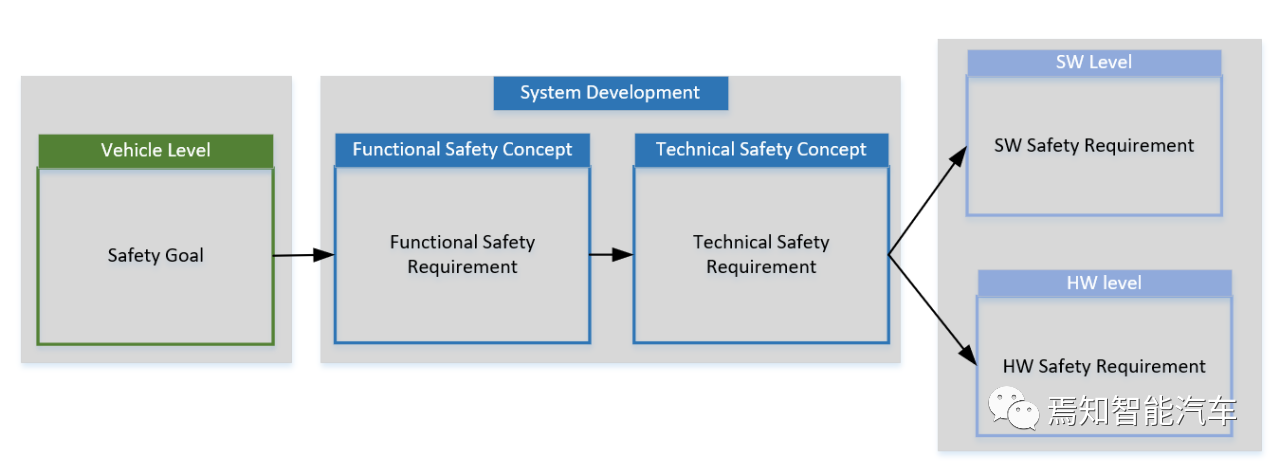
Introduction of Safety ConceptThe essence of development is essentially the fulfillment of requirements. For the development of the “eBooster+ ESC” system’s functional safety, one of the core tasks is how to convert safety goals into safety requirements, which are essential elements in the system architecture of “eBooster+ ESC”. According to ISO 26262, this work includes the development of functional safety concepts and technical safety concepts.
In part 3 and part 4 of ISO 26262, several key proprietary terms are repeatedly mentioned:
- Safety Goals
- Functional Safety Concept
- Functional Safety Requirements
- Technical Safety Concept
- Technical Safety Requirements
When each of these concepts is examined independently, they are not difficult to understand, but can become confusing when they appear together. The following is a comparison and analysis of these concepts.
Safety Goals and Functional Safety Requirements
How are safety goals determined? As mentioned earlier, by analyzing the hazards and risks of the entire vehicle, identifying the hazards and hazardous events that need to be prevented, mitigated or controlled, developing safety goals for each hazardous event, and associating the Automotive Safety Integrity Level (ASIL) with each safety goal. For example:
The vehicle should avoid a driver’s deceleration being too small when braking, ASIL D.When there is a possibility that a certain item could cause a hazardous event for a safety goal, the item needs to consider this safety goal. For example, if the “eBooster+ ESC” system has an interface that can lead to non-intended deceleration, the “eBooster+ ESC” inherits the safety goal:
“eBooster+ ESC” should avoid too small deceleration when the driver is braking, ASIL D
Thus, the safety goal becomes the highest level functional safety requirement for the “eBooster+ ESC” system.
On the other hand, ISO 26262, part3, 8.4 defines the functional safety requirements as follows:
If applicable, the following should be considered to define each functional safety requirement:
a) Operating modes;
b) Fault tolerance time interval;
c) Safe state;
d) Emergency operation time interval;
e) Redundancy of functions (such as fault tolerance).
This means that functional safety requirements include properties a) – e), in addition to the ASIL level. Since the safety goal is the highest level functional safety requirement, it also includes properties a) – e).
To summarize:
-
The safety goal is the highest level functional safety requirement for the item in question.
-
The safety goal, similar to functional safety requirements, includes properties such as ASIL level, FTTI, and safe state.
Functional safety requirements and technical safety requirements:
As explained in the previous section, the language used by the safety goal and functional safety requirements is like that of the first party, “I need the function to achieve XX”. From this perspective, technical safety requirements are the second party that needs to meet the needs of the first party, and they need to answer “how should the function achieve XX”.
ISO 26262, part3 outlines the derivation of functional safety requirements:The functional safety requirements should be derived from safety objectives and safety status, taking into account the preliminary architecture design. The functional safety requirements should be allocated to the elements in the preliminary architecture design.
As mentioned in ISO 26262, part 4:
Technical safety requirements should be defined based on the functional safety concept, the preliminary architecture design of the relevant item, and the following system characteristics:
a) External interfaces, such as communication and user interfaces, if applicable;
b) Limitation conditions, such as environmental conditions or functional limitations;
c) System configuration requirements.
It is reasonable to understand that as a “client”, functional safety requirements only need to determine “I need to implement XX function” based on the rough architecture. In contrast, as a “service provider”, technical safety requirements must have a clear and refined system architecture to answer “how to implement XX function”.
On the other hand, how can technical safety requirements implement functional safety requirements? The key is to define the necessary safety mechanisms.
Safety mechanism is another crucial concept in ISO 26262, which is defined as:
“A technical solution that is implemented by the functions or elements or other technologies of the electronic and electrical system to detect failures and control failures in order to achieve or maintain a certain safety status.”
To summarize:
Neither safety objectives nor functional safety requirements are expressed as technical solutions, but as functional purposes. Technical safety requirements focus on explaining “how to do”.
Technical safety requirements implement “how to do” by defining specific safety mechanisms.
Functional safety concept and technical safety concept can both be summarized in one sentence:
- Functional safety concept: To achieve the functional safety objectives, all activities that assign the functional safety requirements to the elements of the preliminary architecture or external measures.
- Technical safety concept: the sum of all activities to design system architecture and technical safety requirements to meet functional safety requirements.
Based on this, we can say that the process of defining functional (technical) safety requirements is the process of developing functional (technical) safety concepts, which some companies habitually refer to as “safety concept development”.
According to this explanation, Safety Concept Development seems to be defining practical system solutions and requirements, which contradicts the sense of “Concept” in the terminology. However, if we look at the entire functional safety development from a bird’s eye view, Safety Concept Development belongs to the system-level development, and the output is the requirements for the bottom elements of the system – software and hardware. Only when the bottom elements meet the functional safety requirements upon completion of Safety Concept Development can the product be considered functionally safe. From this perspective, the term “Concept” is quite accurate.
Example of Safety Concept Design
Next, we will use the HBC (Hydraulic Brake Failure Compensation) function as an example to introduce the key steps in safety concept design.
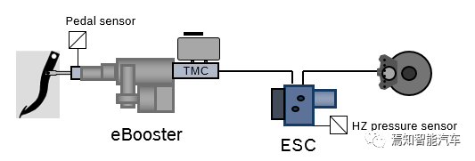
ESC and eBooster share a hydraulic system in the car, and they work together according to the following principles:
-
eBooster and ESC share a set of brake oil pots, brake master cylinders, and brake lines.
-
The power-assisted motor in the eBooster generates driving force to push the master cylinder piston to make the brake fluid in the oil pot flow into the master cylinder line and then into the ESC intake valve. Through the pressure regulation and intake valves in the ESC, the brake fluid flows into the 4 wheel pistons, thereby establishing braking force.- When the eBooster is not functioning, ESC can independently control the brake fluid to enter the wheel cylinder from the master cylinder, thereby establishing braking force.
-
The dynamic response speed of eBooster’s pressure buildup is faster than ESC’s active pressure buildup, and the NVH performance is better. Therefore, eBooster is the main executive device in the braking control system.
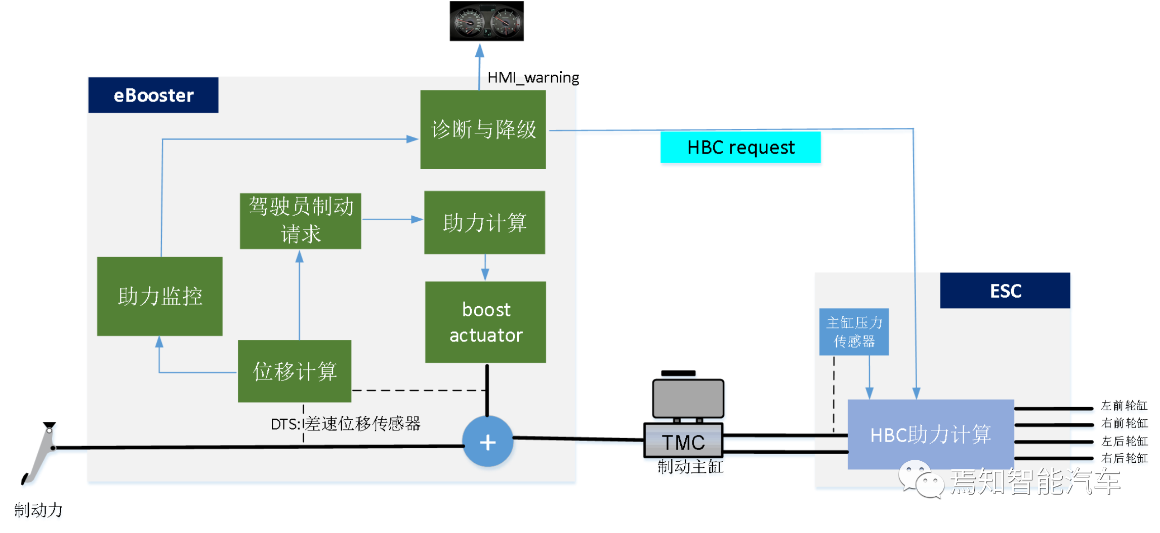
Working in conjunction with ESC, more functions can be derived. For example, according to regulatory requirements, for a comfort braking system, the system must provide a deceleration of at least 6.43 m/s² when the driver applies a braking force of 500N. Normally, eBooster can meet this requirement, but when eBooster fails to provide assistance, ESC is required to take over in a timely manner and achieve the above requirements through active pressure buildup. This is the basic principle of the HBC (Hydraulic Brake Failure Compensation) function integrated into the ESC system.
When the HBC function is activated, when the driver steps on the brake pedal, the master cylinder pressure changes, and the HBC function recognizes the driver’s braking intention based on the master cylinder pressure changes, controls the pressure buildup pump to work actively to establish wheel cylinder pressure, thereby achieving driver assistance.
Determining the HBC Function RequirementsBased on the introduction above, the following functional requirements for HBC can be listed:
- FR1: eBooster should monitor its own boosting capability correctly.
- FR2: When it’s detected that eBooster cannot provide enough boost, it should send an HBC request to the ESC.
- FR3: When it’s detected that eBooster cannot provide enough boost, it should disable its own boosting function.
- FR4: When an HBC request is received, ESC should activate the HBC function.
- FR5: ESC should correctly calibrate the HBC boost curve to ensure that the braking system can provide a deceleration of no less than 6.43m/s² when the driver applies a braking force of 500Nm.
Determining Safety Objectives
Select a safety objective from the previous article and add additional safety attributes (such as FTTI, fault amplitude, etc.).

Determining Functional Architecture
The first purpose of determining the functional architecture is to clarify the input and output of the function. Although there are many interfaces between the standard eBooster and ESC, the interfaces involved in HBC functionality are limited. Therefore, to simplify the analysis, only the interfaces related to HBC are focused on here.
The second purpose of determining the functional architecture is to organize the signal chain of the function, which is very helpful for later functional safety analysis. The functional architecture of HBC is organized as follows:
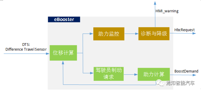 An important input. The control principle of eBooster is: when the driver steps on the brake pedal, the input rod pushes the plunger to move, and the eBooster control motor rotates in real-time to ensure that the travel difference between the plunger and the valve body is zero, thus achieving power assistance. The role of the DTS sensor is to measure the travel difference in real-time.
Determination of Functional Safety Requirements for Output Signals
The functional safety requirements for the output signals of the function come from the safety goals of the relevant top-level items.
According to the regulatory requirements of ECE-R13H and GB13594, in the event of electronic power failure, a passenger car must still ensure that the driver can generate a deceleration of 2.44 m/s² when stepping on the brake pedal with 500 Nm of force applied. The mechanical design of eBooster should also meet this regulatory requirement.
ISO 26262 states that:
In the process of hazard analysis and risk assessment of relevant items, available and sufficiently independent external measures are beneficial.
Therefore, the mechanical components of eBooster can be defined as “external measures”. Due to the existence of this external measure, E/E system failures will not cause ASIL D hazards, so this Safety Goal can be reduced to ASIL C for eBooster, with specific requirements as follows:
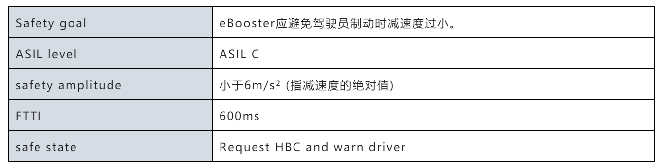
Due to the presence of the HBC function, for vehicles equipped with eBooster+ESC brake systems, when the whole vehicle violates SG1, only when the following two conditions occur simultaneously:1. Correct calculation of BoostDemand when the driver depresses the brake pedal
- ASIL: A (C)
- FTTI: 600ms
- Safety amplitude: Error less than 600Nm (assuming a deceleration of 6m/s² requires a target boost value of 600Nm)
- Safe state: BoostDemand returns to zero
- ASIL C requirements for eBooster to avoid common cause failure that leads to both boost function malfunction and diagnostic failure
Note: This decomposition is valid only if the eBooster boost function and the eBooster boost function monitoring and diagnostic are completely independent and do not affect each other. This means that eBooster needs to avoid having a common cause failure that leads to both boost function malfunction and diagnostic failure – ASIL C.
Considering this requirement, eBooster needs to be designed with both software and hardware in mind, which is complex and beyond the scope of this discussion. The focus now turns back to the two output signals of eBooster:
(1) Target boost value: BoostDemand
BoostDemand is the boost value calculated by eBooster. The functional safety requirements for BoostDemand include:
- SR1: eBooster needs to correctly calculate BoostDemand when the driver depresses the brake pedal
- ASIL: A (C)
- FTTI: 600ms
- Safety amplitude: Error less than 600Nm (assuming a deceleration of 6m/s² requires a target boost value of 600Nm)
- Safe state: BoostDemand returns to zero
This functional safety requirement actually contains two functional requirements:- SR1-1: eBooster needs to calculate the boost demand correctly when the driver steps on the brake pedal. ASIL A (C)
- SR1-2: When eBooster fails to calculate the boost demand correctly, it needs to reset the boost demand to zero within 600ms. ASIL A (C)
(2) HBC Request: HbcRequest
Assuming ESC sets HbcRequest to 1 to activate HBC, ESC needs 200ms to make a judgment on the driver’s brake and establish corresponding pressure on the wheel cylinder. Therefore, to meet the Safety Goal’s FTTI requirement, eBooster needs to detect the power assist problem correctly within 400ms and send out the HBC activation request.
Based on this, the requirements for HbcRequest are:
-
SR2: eBooster should send out the HBC activation request with HbcRequest=1 when monitoring power assist function abnormality. ASIL: B (C)
-
FTTI: 400ms
Determine functional safety requirements for signal chain and develop
Functional safety development is a collaborative process, including collaboration between suppliers and OEMs or between different roles of engineers within a supplier or OEM. Regardless of the collaboration model, the functional safety requirement for a certain function is actually a requirement for the output signal of the function. To ensure that the output signal meets the requirement, it depends on three factors:
-
Input signal meets functional safety requirements
-
Software module meets functional safety requirements
-
Hardware meets functional safety requirements
Once the functional safety requirements for these factors are determined, functional safety development is carried out according to ISO 26262.
Release functional safety requirements for input signalsAfter completing the functional safety analysis, software engineers need to promptly release the functional safety requirements for input signals to signal providers. The interface for this work is usually the system-level functional safety engineer. Take suppliers as an example, the common process is that software engineers summarize the functional safety requirements for input signals to the system functional safety engineer, and the system functional safety engineer summarizes all input signal requirements and releases them to the OEM’s system functional safety engineer. The OEM’s system functional safety engineer confirms whether the functional safety requirements can be implemented and feeds back the results to the supplier, which can be OEM development engineers or another supplier. If it cannot be implemented, both sides need to discuss whether to change the current safety concept together. From this perspective, the functional safety requirements for input signals are the windows that promote functional safety cooperation between the OEM and the supplier.

This article is a translation by ChatGPT of a Chinese report from 42HOW. If you have any questions about it, please email bd@42how.com.