
Author: Zhu Yulong
In the World New Energy Conference, CATL (Contemporary Amperex Technology Co. Limited) shared their overall strategy and technology breakthroughs. One of the interesting points is how CATL divides its product segments and how they allocate technologies to their customers.
Currently, CATL provides several options:
-
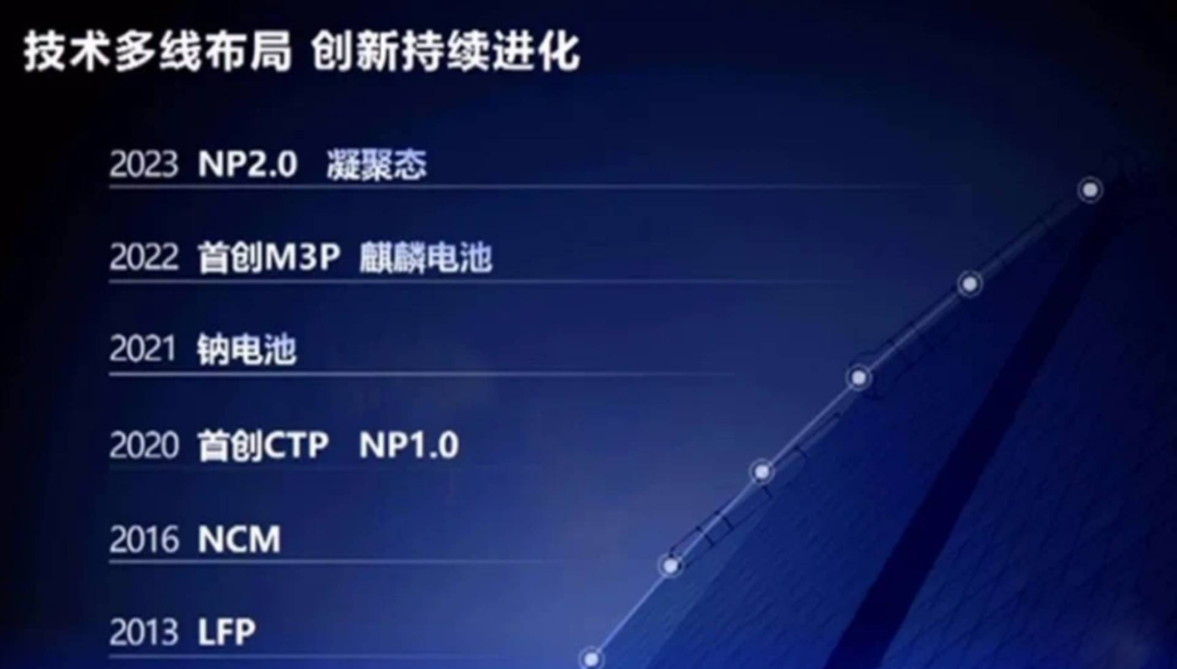
CTP technology: from CTP1.0, CTP2.0 to CTP3.0.
-
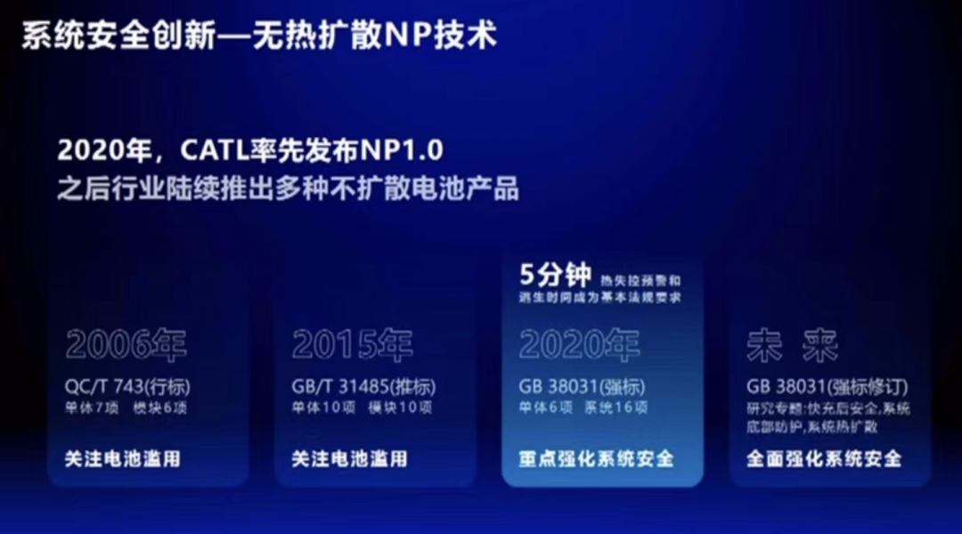
NP technology: from NP1 to NP2, with NP3 and NP4 planned in the future.
-
Chemistry system: from LiFePO4 to M3P and from NCM523 to intermediate-Ni-High-Voltage, from high-Ni/Si-doped to solid-state batteries.
It’s like a father with many sons. The generation-over-generation technology changes make it difficult to understand clearly.
CATL’s Safety Technology
Currently, CTP3.0, aka Kirin battery, is a prevalent choice. It is a series of batteries designed to enhance compatibility and versatility. The primary requirement of these batteries is to support various cell sizes and material systems.
The layout of this battery system includes:
-
High assembly rate: a modular system that simplifies the longitudinal and transverse beams (eliminating the latter).
-
Thermal protection and complete strategy: concentrated around the high energy density, Ni-rich ternary cathode materials beyond 250Wh/kg, and whether it meets the requirements of NP.
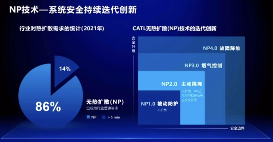
During this communication, the scaling of No-heat-diffusion was observed at various levels:
-
NP1 passively protected to limit diffusion. This is the most basic requirement that the industry took a long time to achieve.
-
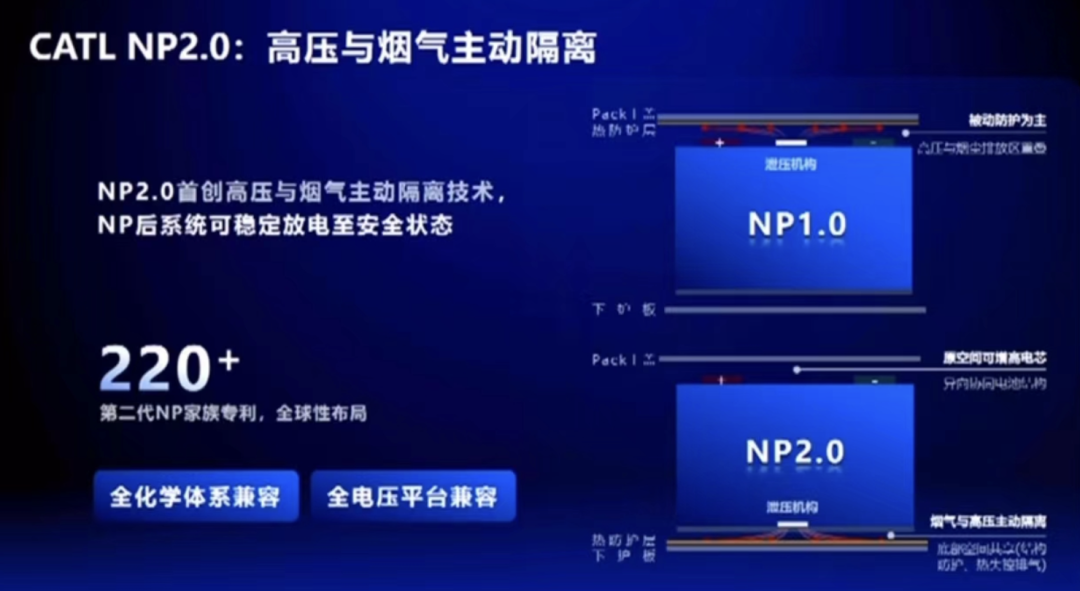
NP2 actively isolated and prevented spread, enabling stable discharge into a safe state.
-
NP3 smoke control: This refers to the directional control of harmful substances discharged by enterprise cells within a certain range.
-
NP4 Fault reduction: This means that after the cells burn out, the vehicle can still be used by bypass processing.
-
The thermal control of high-rate electric cores: automotive companies require high-energy and high-rate electric cores while utilizing temperature control to prevent rapid decay of electric cores.
-
CTP3.0 technique enables transitions to CTC.
NP technology discussionCurrently, the design strategy for thermal runaway protection from NP1 to NP2 considers both the 4680 and Volkswagen cell designs. Thus, we must take into account a number of factors when retrofitting to the Pack cover, requiring sufficient durability and heat-resistant materials. When the overall design cost and weight reach a certain point, the design considerations shift towards placing the pressure relief valve below.
Several variants have been proposed as follows:
- Kirin Plan 1: upright, using NP1.0, relief structure on top, positive and negative output on top.
- Kirin Plan 2: upright cell, using NP2.0, relief structure below, positive and negative output on top, with sufficient stability from the downward relief, facing the lower casing.
- Kirin Plan 3: inverted cell, using NP?, relief structure below, positive and negative output below, with comprehensive consideration for the Busbar electrical connection and casing.
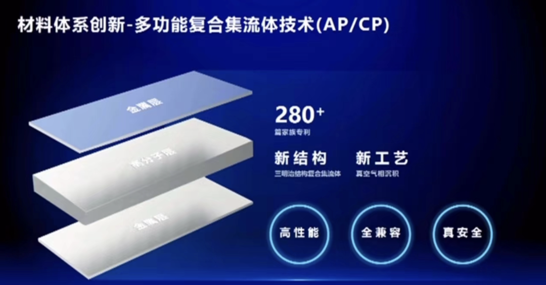
My understanding is that Kirin’s multi-functional integrated liquid-cooled plate component is mainly geared towards fast charging, serving as both a cooling plate when in use, a structural component when bearing mechanical force, and a buffer space for cell expansion. Regardless of whether the Kirin battery cell is upright or inverted or the pressure relief port is downwards, the entire lower casing also becomes part of the structural support. The specific configurations for these layered components are indistinguishable to us, given how Ningde classifies these products. After all, all the Little Kirins are related, like the legendary progeny of the Dragon, born in sets of nine.
Of course, everyone is keen to know about the composite flow channel fluid, which is expected to be gradually integrated into the cell system alongside the high-nickel cell products used by Ningde Times between the second half of 2022 and 2023. This aims to reduce the internal short-circuit probability of the cell and mitigate the fire risk associated with fast charging.
Conclusion: Discussing Ningde Times’ battery technology truly requires great effort to piece together all the different components. As a large company, with so many teams iterating and developing various innovative ideas, it is indeed challenging for outsiders to understand. In the future, we will take a closer look at Avida’s battery system design, our very own offspring.
This article is a translation by ChatGPT of a Chinese report from 42HOW. If you have any questions about it, please email bd@42how.com.