Blade Battery System – Part 2 Battery Management System
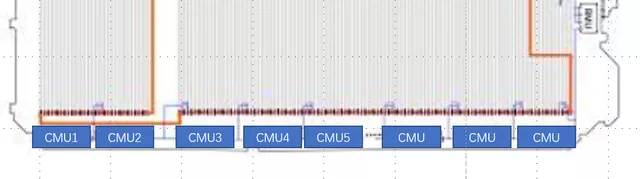
In my previous article “Disassembly of Blade Battery System Part 1 – Electrical Design”, I shared the basic line connection of the system. By increasing the integration efficiency at the cell level, BYD seems to use the CMU part as a wire, as shown in the figure below.
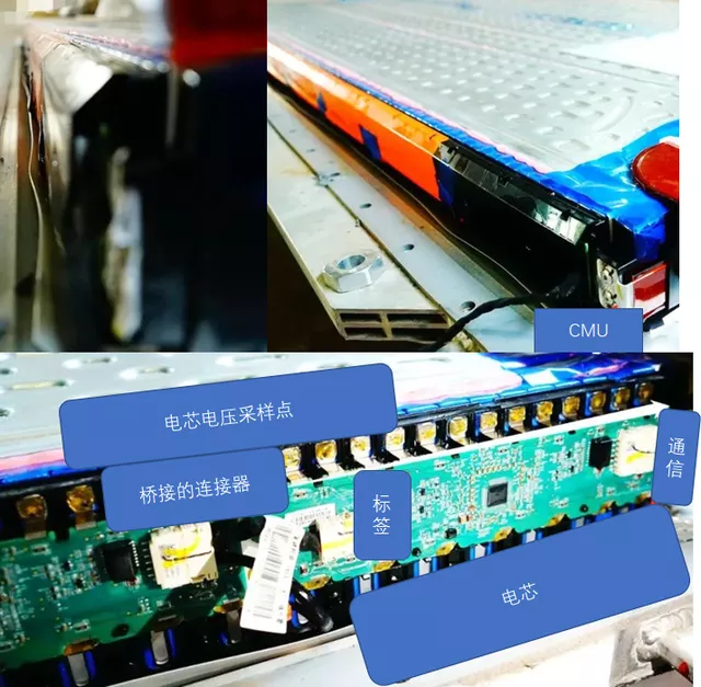
Due to the long length of the battery system, a lot of PCBs are used to achieve the connection function (each CMU has 22 sampling points, and 11 battery sections can be sampled), and the CMU used is adjusted according to the total capacity and number of series due to the Blade battery’s multi-cell series connection.
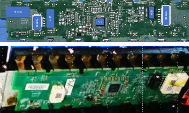
Regarding the design of the CMU, it is fixed on the output pole of the cell by laser welding, achieving the effect of supporting the CMU. The whole board mainly includes AFE and daisy-chain chips. The most important thing here is that BYD has eliminated the balance circuit, without discharge resistors or triodes that control discharge resistors, only retaining the input filtering circuit and communication circuit. This CMU design has several special features:
- The design of the balance circuit
- No cell temperature sampling, only relying on the onboard temperature sensor of AFE for replacement
Note: Let’s discuss this together. Looking at the long-term evolution, can BMS still work without a balancing circuit? BYD still has a balance circuit in the ternary version of the product, and it is still included in the Blade battery version.
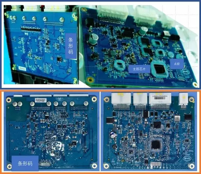
Main Control Circuit
From the information I have found, the Blade battery system has two versions: 3 connectors and 4 connectors. The common parts of the two versions are: CMU communication circuit interface, external communication control interface, two relay controls, and current shunt interfaces.
 In the previous system version of PHEV, BYD implemented a three-level structure of CMU + adapter system + BMU. Brother Hu Yaoshan conducted a basic analysis, which I will quote directly.
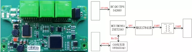
The main control chip uses a similar MC9S12XET256, including a low-side drive to control relays and analog sampling to sample sensors. This is relatively simple, so I won’t say much more.
Summary: when dismantling the battery management systems of Wuling Mini EV and Han EV, my intuitive feeling is the same: when it comes to the design of battery management systems, the further you go, the more you gradually omit the original design step by step. It seems that this approach is giving up consideration for the overall design of the vehicle system. If I follow my previously accumulated engineering thinking, then I’m having a little trouble dealing with these two models.
This article is a translation by ChatGPT of a Chinese report from 42HOW. If you have any questions about it, please email bd@42how.com.