In the previous post “Yvon Shong: Exploring Autonomous Driving Sensors (I) – LiDAR”, we introduced the data and characteristics of LiDAR sensors. In this post, we will introduce the millimeter-wave radar which is equipped in most Advanced Driver Assistance Systems.
Due to the lengthy 20,000-word count and the complexity of the performance indicators of millimeter-wave radar sensors, we have placed the complex formula derivation at the end of the article, ensuring the coherence of symbol definition, and making sure that everyone can comprehend each formula by recalling signal processing from its foundation.
It’s worth noting that the principle of FMCW millimeter-wave radar involved in this article is identical to FMCW LiDAR. If you are interested in FMCW LiDAR, you can refer to the formula derivation part in this article.
Introduction to Millimeter-Wave Radar
Millimeter-wave radar is a radar that operates on millimeter waves, with a frequency range of 30 GHz to 300 GHz, a wavelength of 1 to 10 mm, between microwave and centimeter-wave, with some advantages of microwave and lidar. Various countries assigned different frequency bands to millimeter-wave radar used for vehicles, but mainly concentrated in 24 GHz and 77 GHz, and some countries (such as Japan) used 60 GHz frequency bands.
In the electromagnetic spectrum, this wavelength is regarded as a short wavelength, which is one of the advantages of this technology. Compared with centimeter-wave radar, millimeter-wave radar has the characteristics of small size, easy integration, and high space resolution. Therefore, the size of the system components (such as antennas) required for processing millimeter-wave signals is indeed small. Another advantage of a short wavelength is high accuracy. The millimeter-wave system around 77 GHz (corresponding to a wavelength of about 4 mm) will be able to detect movement as small as a few tenths of a millimeter.
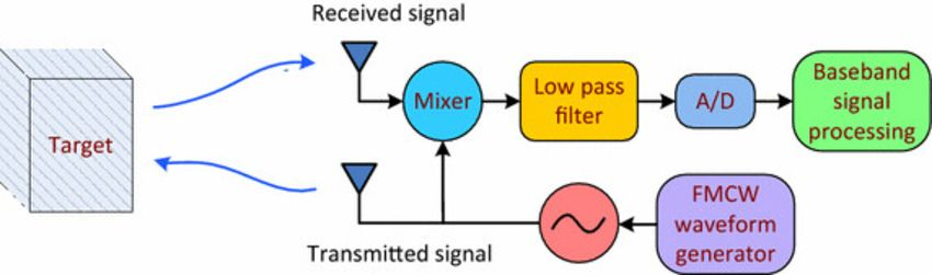
The basic working principle of the millimeter-wave radar is to generate electromagnetic waves with specific modulation frequencies (FMCW) through high-frequency circuits, and transmit electromagnetic waves through antennas and receive electromagnetic waves reflected from targets. It can perform ranging, velocity, and azimuth angle measurements on multiple targets at the same time. Velocity measurement is based on the Doppler effect, through calculating the frequency change of the radar wave returned to the receiving antenna, one can obtain the target’s relative speed to the radar and flight time to get the distance to target. The azimuth measurement (including horizontal and vertical angles) is obtained by calculating the phase difference of the radar wave reflected by the same target received by an antenna array.
 Compared with pulse radar, one major advantage of frequency-modulated continuous wave (FMCW) radar is its low transmitting power, small size, low cost, and performance of measuring the distance and velocity of targets that is not affected by ambient lighting, and does not require additional auxiliary light sources for illumination. Its high operating frequency also means that the overall solution has a smaller size.
In FMCW radar, since the transmission and reception are simultaneous, there is theoretically no distance measurement blind zone as in pulse radar. It can directly measure the Doppler frequency shift and the probability of static targets, and the average power of the transmitted signal is equal to the peak power, requiring only low-power devices. It has advantages such as ease of implementation, relatively simple structure, small size, light weight, and low cost.
Classification
Distance
Radar can be divided into:
- Short-range radar: with a large detection range, but a relatively short detection distance.
- Long-range radar: with a narrow detection range, up to 250 meters.
Electromagnetic radiation mode
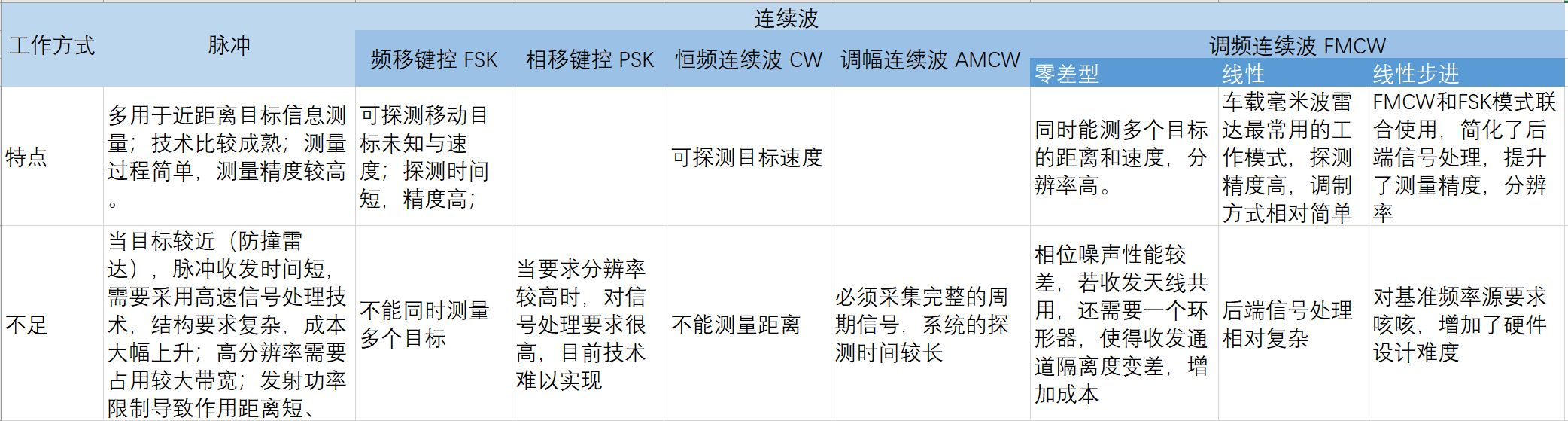
It can be divided into two working modes: pulse mode and continuous wave mode, of which continuous wave mode can be further divided into:
- Frequency-shift keying (FSK): the most common is the dual-frequency FSK system that carries binary 1 and 0 with two frequencies.
- Phase-shift keying (PSK): the modulated carrier phase of a PSK system carrying binary is either the same as the unmodulated carrier phase or 180° out of phase.
- Continuous wave (CW)
- Frequency-modulated continuous wave (FMCW)
Different modulation forms of FMCW radar:
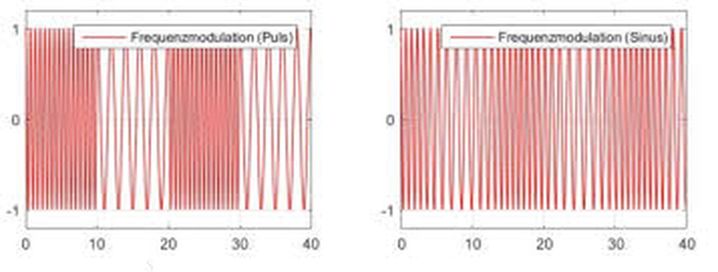
The hardware composition of radars with different frequency modulation modes is basically the same, with only a few circuit modules, circuit parameters, and signal processing algorithms being different. For measurement of a stationary object, sawtooth wave modulation is sufficient; for moving objects, the triangle wave modulation is usually used; sine wave modulation is used less frequently.
Frequency band
In the automotive industry, millimeter wave radars mainly used in the field of autonomous driving operate at two frequency bands:
- 24 GHz band: 24.0 GHz to 24.25 GHz, with a narrow bandwidth of 250 MHz and a wavelength greater than 1 cm, strictly speaking, belong to centimeter wave radars. The band also includes a 5 GHz ultra-wideband (UWB) band. After January 1, 2022, UWB bands cannot be used in Europe and the United States, and only narrowband frequencies can be used in the long term.
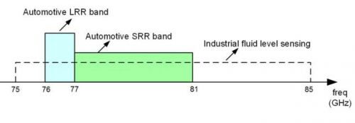
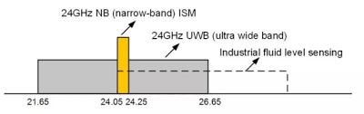 – 77 GHz Band: The frequency range of 76-77 GHz can be used for remote automotive radar, and it has the advantage of equivalent isotropic radiated power, while also meeting high transmission power and wide operating bandwidth, which can achieve long-range detection and high distance resolution at the same time. The shorter wavelength leads to a significantly reduced size of the transmitting and receiving antenna, and thus a smaller radar volume. The 77-81 GHz Short-Range Radar (SRR) frequency band is a newly added band that can provide a wide scanning bandwidth of up to 4 GHz, which is very suitable for applications that require high range resolution.
Hardware Structure
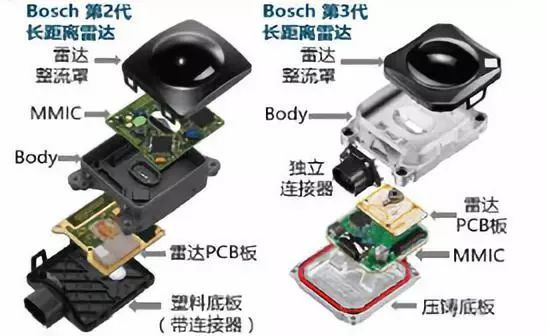
The radar used in cars is not as large as military radar. It is a small sensor that can be easily installed under the front grille or bumper.
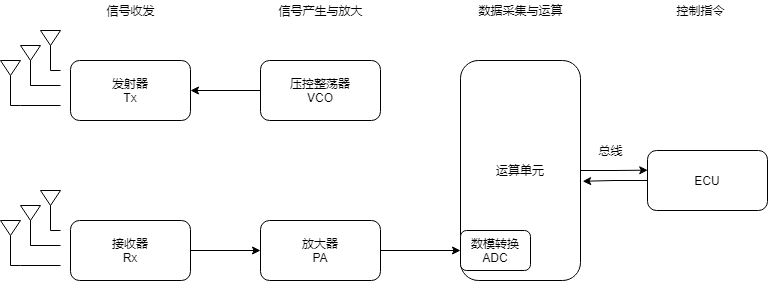
The high-frequency signal is generated by a voltage-controlled oscillator, and a portion of it is forwarded to the transmitting antenna after being amplified by a power divider, while the other portion is coupled to the mixer, mixed with the received echo, and then low-pass filtered to obtain baseband intermediate-frequency (IF) signal, which is sent to the signal processor after being converted by an ADC.
- Monolithic Microwave Integrated Circuit (MMIC)
It includes various functional circuits such as low-noise amplifiers (LNAs), power amplifiers, mixers, detectors, modulators, voltage-controlled oscillators (VCOs), phase shifters, including transmit (TX) and receive (RX) radio frequency (RF) components in the transceiver system, as well as clock and other analog components, as well as digital components such as analog-to-digital converters (ADCs), microcontrollers (MCUs), and digital signal processors (DSPs).
Mixer: In FMCW radar, a mixer subtracts the echo signal from the frequency synthesizer’s sweep signal to obtain a frequency-shifted or intermediate-frequency (IF) signal.
- Radar Antenna High-Frequency PCB Board
The mainstream solution for millimeter-wave radar antennas is microstrip array, which integrates high-frequency PCB board on a normal PCB substrate to achieve the function of an antenna, and needs to maintain the sufficient signal strength of the antenna in a smaller integration space.## Antenna
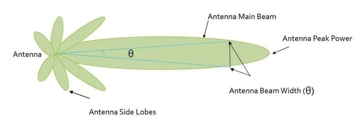
Antennas increase signal strength by focusing energy in the desired direction, and the beam width of the antenna determines the radar sensor’s field of view, such as the number of lanes covered horizontally. Antenna radiation includes not only the main lobe but also the sidelobes. The sidelobes point in different directions, sensing targets outside the main lobe and may generate false alarms. To avoid sidelobe detection, sidelobe levels must be suppressed to 30 dB or more below the main lobe peak.
Specifications
Radar performance specifications depend on the selection of transmitted signals, including the following parameters:
- Distance
Range Accuracy: used to describe the accuracy of the radar’s distance parameter estimation for a single target, determined by the signal-to-noise ratio (SNR) of the echo signal. The effective noise bandwidth of the FMCW radar is inversely proportional to its frequency modulation time. The longer the frequency modulation time, the lower the effective noise bandwidth and the higher the resolution.
Maximum detection range: The maximum relative distance at which obstacles can be detected, usually 250m. Maximum detectable speed is inversely proportional to the spatial gap between adjacent chirp signals.
Range resolution: the minimum distance at which multiple targets are distinguished by the radar, mainly determined by the signal bandwidth. With increasing chirp signal bandwidth, the range resolution increases.
- Velocity
Maximum detectable speed: the maximum relative speed at which obstacles can be detected, usually 240 km/h.
Velocity resolution: higher with increasing frame duration.
- Angle
Field of view: the range of view that can be detected. The horizontal range is generally ±60°, and the vertical view angle is generally ±15°.
Angular accuracy: used to describe the accuracy of the radar’s heading estimation for a single target.
Maximum detectable targets: the maximum number of targets that can be detected, usually 24-32.
Angular resolution: depends on the radar’s operating wavelength, antenna aperture size, and number of TX/RX antennas.
Data
Similar to LiDAR, mmWave radar data is composed of point clouds, with each point containing 2D/3D location, reflectivity, and radial relative velocity. There may be some differences between specific models, mainly due to factors such as whether the device supports 3D and velocity measurement.Everyone can use the Oxford Radar Dataset from the Oxford group for dataset development. This radar dataset collected multiple segments of data in urban environments, using a 76 GHz ~ 77 GHz millimeter wave radar developed by Navtech. The radar uses a narrow beam for mechanical scanning, similar to mechanical LiDAR, with a relatively low resolution and a beam width of 1.8°. The mechanical scan occurs at intervals of 0.9° each time, obtaining 400 angular measurements per rotation. The mechanical rotation speed is about 4 Hz, with a distance resolution of 4.32 cm and a maximum range of 163 m.

Characteristics
- Compared to LiDAR
The debate between Radar and LiDAR is a hot topic, but these sensors are actually complementary. Expensive LiDAR can generate high-resolution images based on the reflection of the laser by the target, providing precise shape and position information, but it cannot work in harsh weather conditions.
Radar does not have the ability to generate high-resolution images, but it has high-precision velocity estimation based on the Doppler effect. In addition, the wavelength of the radar allows it to perceive targets in harsh weather conditions, and most importantly, at a lower manufacturing cost.
- Advantages
- Small size and minimal impact on the appearance of the car after installation;
- Strong detection ability for longitudinal target distance and speed;
- High-precision measurement for both stationary and moving targets;
- Works around the clock without being restricted by weather conditions and has strong penetration capability.
- Disadvantages
- Unable to generate images or recognize image colors;
- Weak reflection from pedestrians, with a low pedestrian resolution;
- Limited detection range and vertical angle, resulting in poor detection of high and small objects;
- Difficulties in distance, Doppler coupling, and transmission and reception isolation;
- In a millimeter-wave radar with volume requirements, the close arrangement of vertical and horizontal antennas can cause severe signal interference;
- The reliability and real-time performance of signal processing algorithms need to be guaranteed, and traditional millimeter-wave radar ECUs may not be able to handle large-scale point cloud processing;
- Increased data storage requirements and the need for additional storage units.
ApplicationsThe frequency modulated continuous wave (FMCW) radar has been widely used in the automotive industry for various aspects, including safety and comfort performance, such as blind spot detection, lane changing assistance, autonomous cruise control, and parking assistance. Regardless of weather and surrounding lighting conditions, the radar can reliably and accurately detect and locate obstacles.
-
Advanced Driver Assistance Systems (ADAS)
Currently, manufacturers mainly use vision sensor technology and millimeter-wave radar systems to achieve driving assistance. Long-range radar (LRR) supports various functions and can easily handle distances from 30 to 200 meters, while short-range radar (SRR) can detect distances below 30 meters. -
Proximity sensing
With the high distance resolution of the radar and its ability to detect obstacles at close range, it can be used for collision prevention when opening car doors or trunks, as well as for parking assistance. -
Driver vital signs monitoring
The phase shift of the received signals in FMCW radar is highly sensitive to small changes in target position, making it possible to estimate target vibration frequency (such as those caused by breathing and heartbeat) and monitor the driver’s heart rate and breathing frequency to continuously monitor the driver’s vital signs. This small-sized sensor is simple to use and can be embedded in the backrest of the driver’s seat. -
Gesture recognition
Can be used for gesture-based touchless interfaces, including gesture-based opening of car doors/trunk and controlling the infotainment system.
Market
The core chips of millimeter-wave radar mostly come from foreign manufacturers, almost monopolizing the market. In terms of the market share of millimeter-wave radar chips by domestic and foreign companies, currently, the international market is mainly occupied by chip design companies such as NXP, Infineon, and Texas Instruments. The domestic millimeter-wave radar chip industry has not yet formed a scale.
In the global millimeter-wave radar market, Germany, the United States, Japan and other countries dominate the market and are monopolized by manufacturers such as Bosch, Continental, Valeo, Delphi, Denso, and Autoliv. Domestic millimeter-wave radar depends on imports. There is no stable supply system for the 77 GHz millimeter-wave radar chip worldwide. Due to intellectual property and cooperation agreements, chip manufacturers such as Infineon, Freescale, and STMicroelectronics have not opened the supply of 77 GHz radar chips to China. Therefore, the development of 77 GHz millimeter-wave radar in China is restricted, and 24 GHz millimeter-wave radar is the mainstream direction.
According to McKinsey’s research, in 2016, the number of pre-installed millimeter-wave radars in Chinese automobiles reached 1.05 million, of which 63.8% were 24 GHz radar and 36.2% were 77 GHz radar. Bosch and Continental have a global market share of 17%, tied for first place, while Denso and Hella tie for second place with a market share of 11%. The market share of the top seven suppliers amounts to 73%.
Note!!!
The above is basic knowledge about a sensor. If you only want to use radar data and do not want to care about the principle of millimeter-wave radar, you can stop reading here.## Basic Concepts of Signal Processing
- Single Wave Parameters
Wavelength Lambda: The physical length from a point on one wave to the same point on the next wave.
Frequency: The number of waves passing per second, measured in hertz. The higher the frequency, the shorter the wavelength.
Bandwidth: The difference between the highest and lowest frequency components of a continuous frequency band of a signal.
Amplitude: The strength of a signal, related to the radar output power and perceptible receiving signal. The greater the amplitude of the radar signal, the higher the radar visibility.
Radar Cross Section: The ability of a target unit area to reflect radar energy, depending on the target’s physical geometry and external characteristics.
- Frequency Modulated Signal (Chirp)
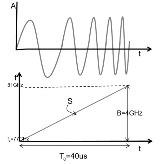
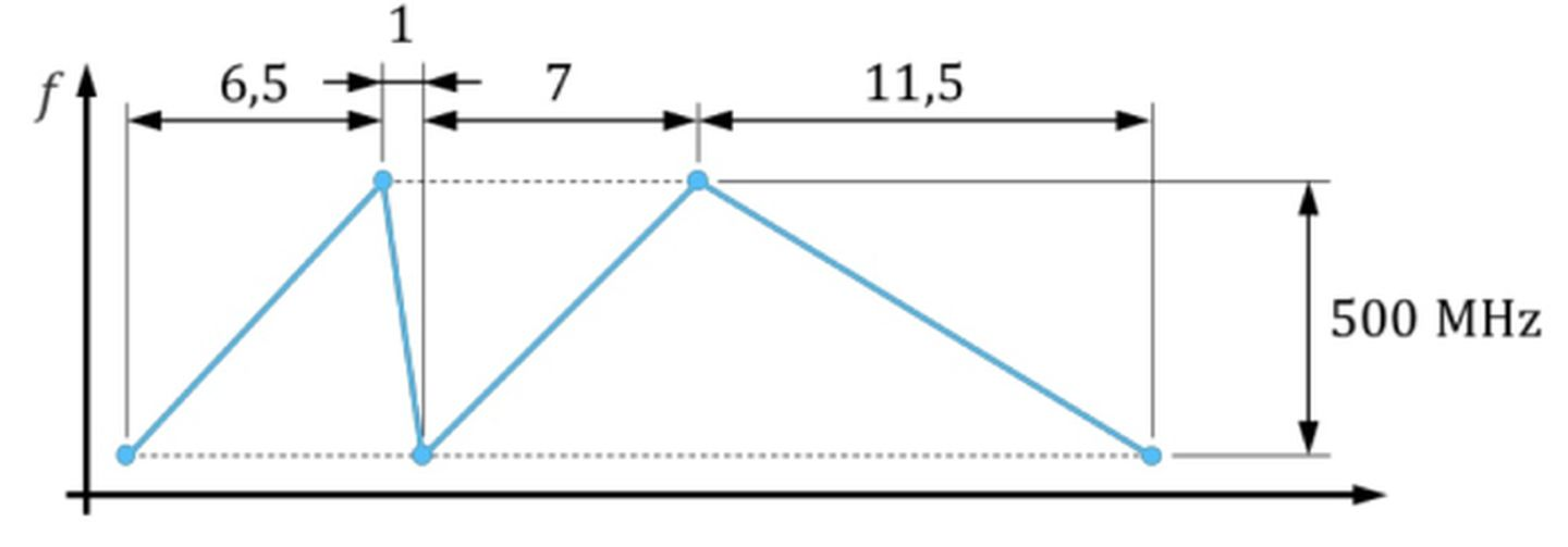
There are two main types of radar: pulse radar and continuous wave radar, which have been mentioned in the previous section. Chirp signal is shown in the following figure:
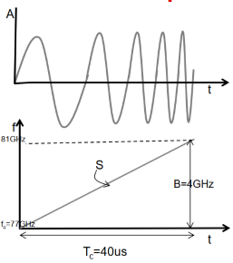
The first is a time-domain signal, and the second is a frequency-domain signal. It can be seen that the frequency of the chirp signal and the duration Tc of the signal are linearly related, so such a chirp continuous wave is also called a linear frequency modulated continuous wave (LFMCW).
There are several main parameters to note in FMCW: bandwidth B, slope S, and signal duration Tc. The signal slope S=B/Tc=100 MHz/us.
- Intermediate Frequency (IF) Signal
In the field of wireless communication, signals are divided into three types according to their frequency: radio frequency (RF), intermediate frequency (IF), and baseband. RF is responsible for receiving and transmitting high-frequency signals, while baseband is responsible for signal processing and storage. IF is the intermediate bridge between RF and baseband that allows the signal to smoothly transition from high-frequency to baseband. IF only describes the degree of signal frequency band.
The IF signal that comes out after mixing actually has more than one frequency band signal through the multiplier. We still need to filter out the signals we need with a low-pass filter.
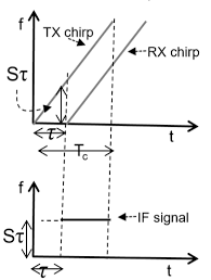 The frequency difference between the radar transmission signal and the echo signal is the intermediate frequency signal, which is a straight line representing a single frequency. Since the distance to the target varies, the returned time is also different, so the intermediate frequency signal is also different, and it can be said that the distance and intermediate frequency signal has a mapping relationship.
The basic formula for radar ranging is:
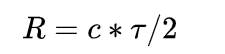
where c is the speed of light and τ is the round-trip time of the electromagnetic wave.
Therefore, the intermediate frequency signal is:
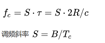
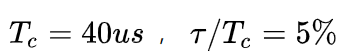
τ is usually very small. For example, when the detection distance is 300 m, the frequency modulation cycle is:
- Sampling of intermediate frequency signal
The intermediate frequency signal is still an analog signal, and it must be sampled by an analog-to-digital converter (ADC) to be sent to the processor for processing.
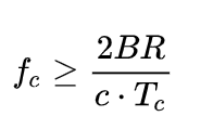
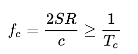
The bandwidth of the intermediate frequency is limited by the sampling frequency of the ADC, because the duration of the signal cannot be infinitely small:
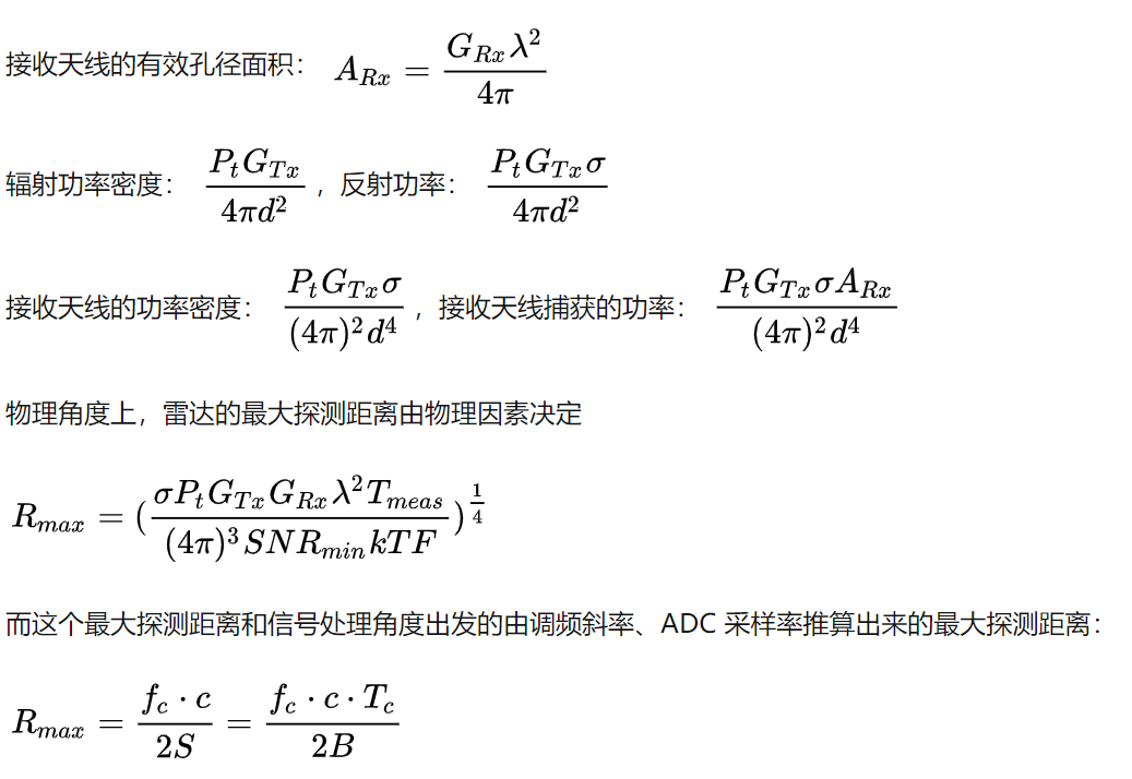
The maximum detection distance of the radar can be obtained:
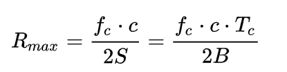
That is, under the condition that the ADC sampling rate remains unchanged, the detection distance of the radar varies inversely with the slope of the signal. If the emission period remains fixed, the detection distance of the radar varies inversely with the bandwidth of the signal. If two waves have the same distance resolution, for the same maximum detection distance, the wave with a larger slope requires a higher ADC sampling rate, but the advantage is that the wave has a shorter period. Therefore, a balance is needed in the selection and design.
- Phase information of intermediate frequency signal
When a single signal is Fourier transformed, it can also reflect the frequency information and phase information of the time-domain signal.
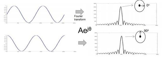
The initial phase of the intermediate frequency signal output by the mixer is the difference between the initial phases of the two inputs.
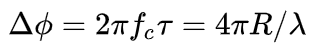
The phase difference between point A-D (and point C-F) is:Translate the Chinese Markdown text below into English Markdown text in a professional manner, preserving the HTML tags inside the Markdown and only outputting the result.
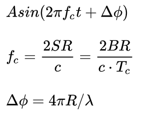
The actual function expression of the intermediate frequency signal is:
- Fourier transform
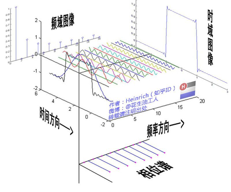
Regarding the Fourier transform, I highly recommend Heinrich’s column, the purpose of Fourier transform is to map the time domain signal to the frequency domain for analysis:
Heinrich: A Tutorial on Fourier Analysis (Complete Version) last updated on 2014.06.06
https://zhuanlan.zhihu.com/p/19763358
FMCW Radar Principle
A single-frequency continuous wave spectrum can estimate relative velocity based on the frequency shift generated by the Doppler effect. However, since we only emit identical sine or cosine signals, the wave received is also periodically changing. Thus, we have no way of knowing how many wavelengths it has gone through from emission to reception. Thus making it impossible to determine the time of flight of the signal and measure the distance.
So, we introduce frequency modulation/amplitude modulation (FMCW/AMCW), which puts the frequency or amplitude of the emitted signal into a continuous state of change, making it possible to measure both range and speed. In the automotive field, we generally use frequency modulation technology.
During the frequency scanning period of the FMCW radar, a continuous wave with a varying frequency is transmitted, and the reflected wave from an object has a certain frequency difference with the transmitted signal. After mixing, several intermediate frequency signals with different frequencies are obtained. Different intermediate frequencies represent different distances. The distance information between targets and the radar can be obtained by measuring the frequency difference.
 The two most common waveforms used in frequency modulated continuous-wave (FMCW) radar are sawtooth and triangular. Sawtooth waveforms typically use only ascending slopes, while triangular waveforms use both ascending and descending slopes.
- Doppler Effect
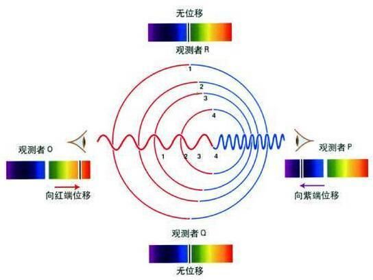
The Doppler Effect is the phenomenon in which the frequency of a wave received by an observer differs from the frequency emitted by the source due to relative motion between them. When the source and the observer are approaching each other, the received and reflected wave frequencies increase. Conversely, when the source and the observer are moving away from each other, the frequencies decrease.
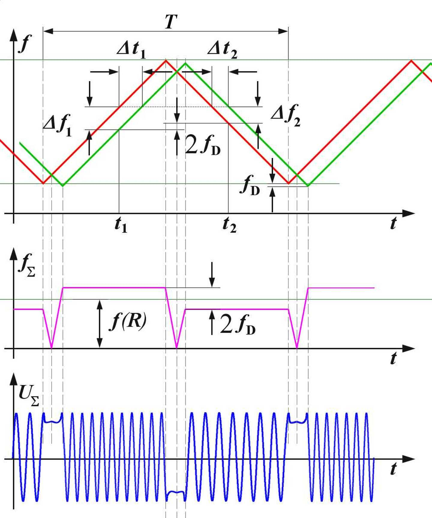
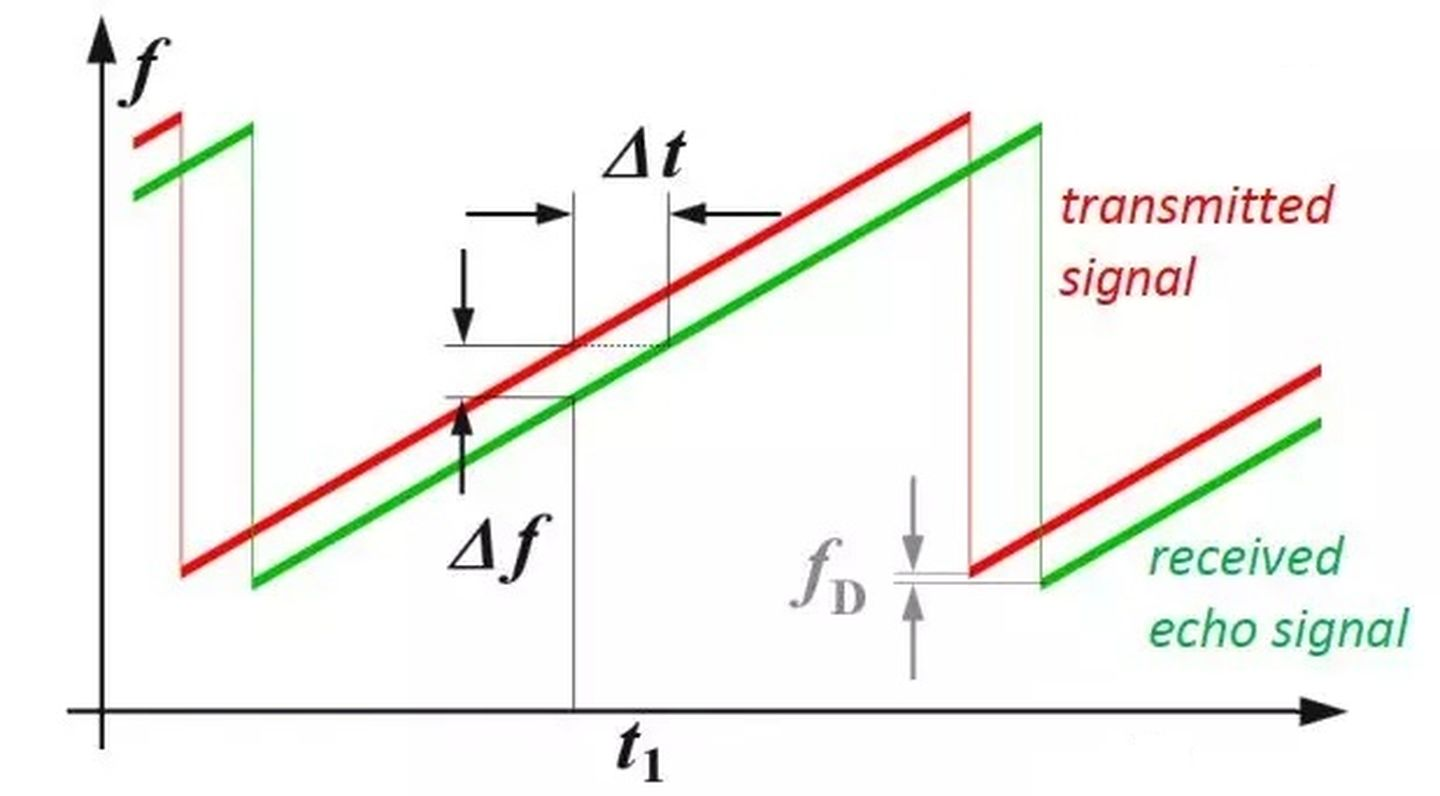
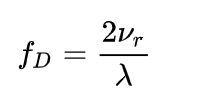
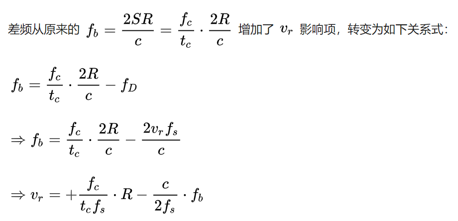
Due to the Doppler effect caused by the motion of the target, the beat frequency (the difference between the received frequency and the ramp frequency) consists of two frequency components: fR (caused by distance) and fD (caused by velocity, proportional to the speed of the target):
It should be noted that in the case of automotive radar, the difference between fD and fR due to the target’s motion is very small. This is due to the small phase change caused by the target’s tiny displacement during each chirp, which typically lasts only microseconds, resulting in millimeter-level displacement. Therefore, it is mainly calculated by measuring the phase change rate between multiple chirps. By measuring the frequency difference caused by the Doppler effect, the radar can determine the target’s speed.
Range Estimation
We can determine the flight time of the radar signal by measuring the frequency shift, and then estimate the flight distance of the target.
Next, we will briefly introduce the principle of range and speed measurement of the radar using triangular FMCW as an example.
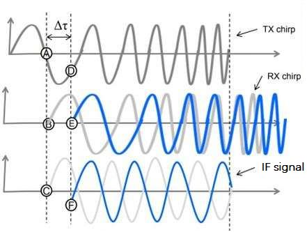
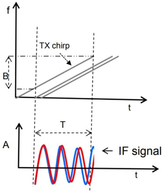
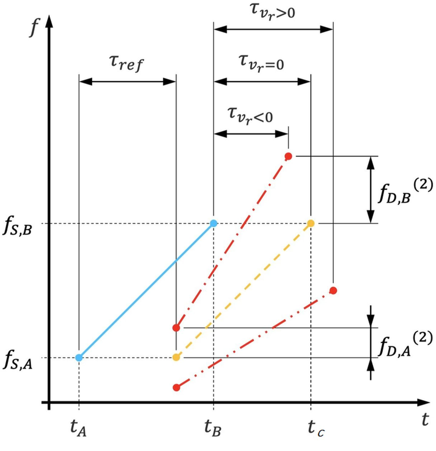
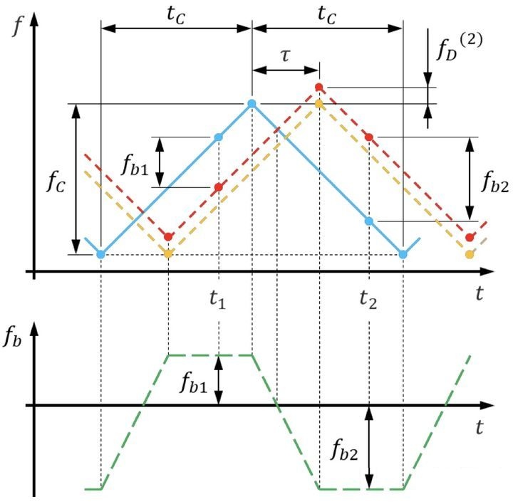
As shown in the figure below, the blue solid line represents the transmitted signal frequency, the red dashed line represents the received signal frequency, tc is half of the sweeping period Tc, fc is the sweeping bandwidth, and τ is the time from signal transmission to reception. The echo signal is delayed due to its round-trip time. In the triangular frequency change, we can perform distance measurement on both the rising and falling edges.
For stationary objects without Doppler effect, the transmitted and received frequencies are identical, and the frequency difference during the rising edge period is equal to that during the falling edge period. However, the ramp frequency of the radar is constantly changing over time. Therefore, when we obtain the beat frequency fb, we obtain the signal transmission time.
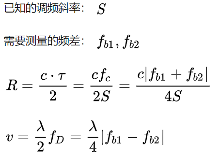
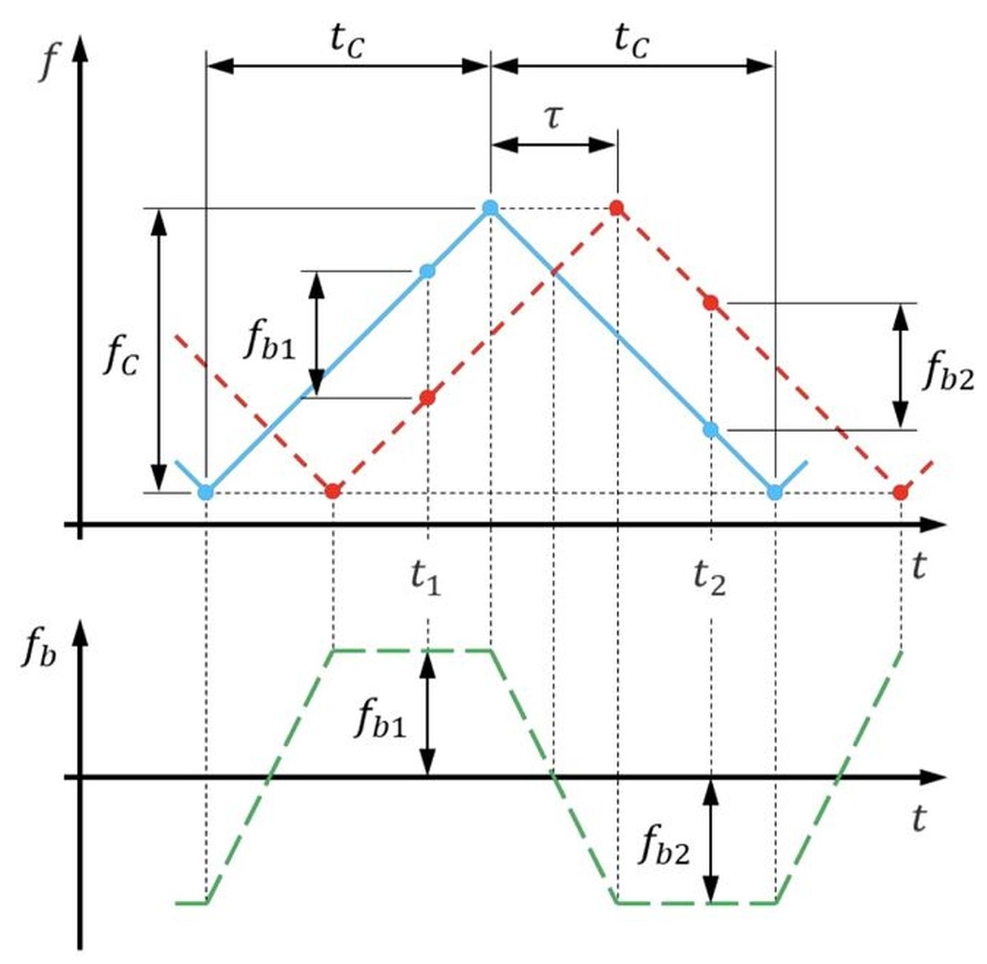 For motion target, the frequency difference during the rising and falling edges is different. We can use these two frequency differences to neutralize the Doppler effect and calculate distance and velocity.
- Distance Resolution
The radar needs to be able to distinguish between two targets that are very close in distance. For example, when the radar’s distance resolution is 4 meters, it cannot distinguish between pedestrians and cars that are 1 meter apart. Distance resolution depends entirely on the bandwidth of chirp.
Assuming that two targets that are very close to each other are detected by the radar, two intermediate frequency signals are obtained after the two echo signals are mixed. The time T of the two intermediate frequency signals is very small, so the frequency difference between the intermediate frequency signals is very small.
If the radar cannot distinguish between the two targets, the radar will consider them as a single target, and the information of the two targets will be merged.
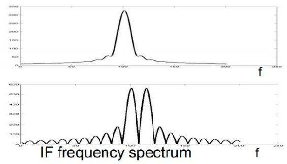
The Fourier transform theory states that by extending the IF signal, the resolution can be improved. To extend the IF signal, the bandwidth must also be increased proportionally. The extended IF signal generates an IF spectrum with two separated peaks.
The Fourier transform theory also states that the observation window (T) can distinguish frequency components that are spaced more than 1/T Hz apart. This means that as long as the frequency difference satisfies the following formula, two single-tone signals can be distinguished:
First, we obtained the formula for the intermediate frequency signal:


Based on the basic principle of linear frequency modulated continuous waves, we know that the frequency difference fc is absolutely greater than the pulse repetition frequency (PRF). Because the larger the time, the smaller the frequency, and the smaller the time, the larger the frequency.
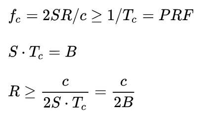 Due to the relative distance R that each Chirp can obtain, the distance resolution depends only on the linearly frequency modulated pulse frequency, that is, the bandwidth of the transmitted signal:

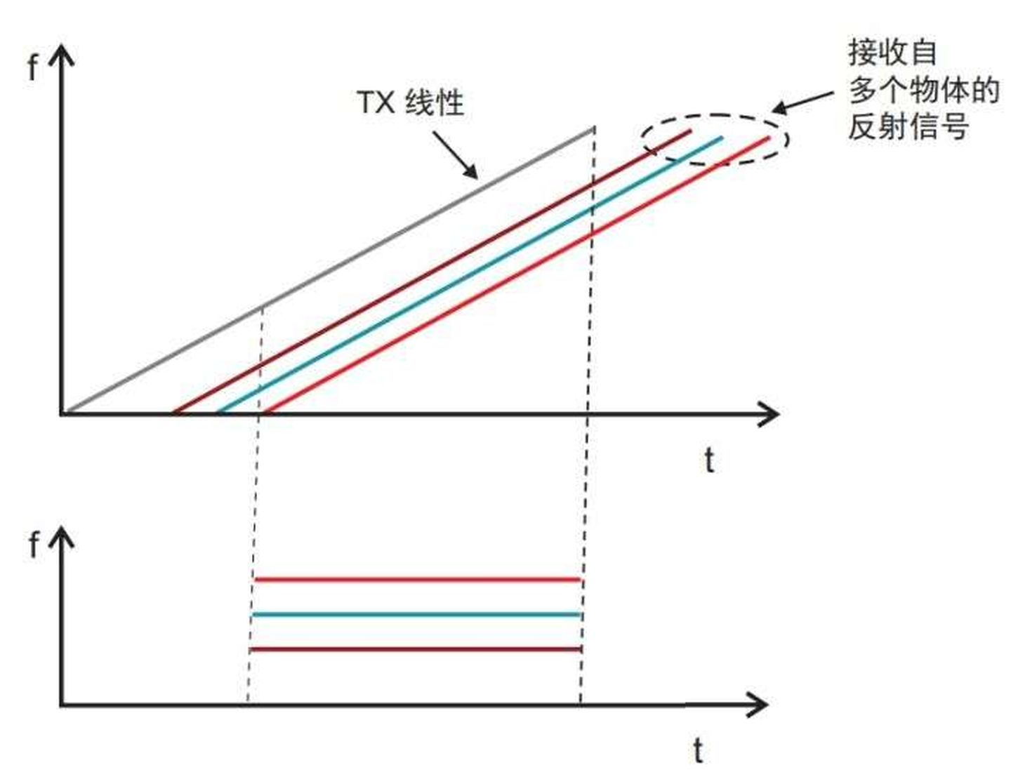
Signals from multiple targets under the same slope have a longer duration and higher frequency resolution as the bandwidth increases. As long as the bandwidth (the frequency range covered) is the same, the distance resolution of the radar will not be affected by the duration of the signal. The following are several typical relationships between bandwidth and resolution:
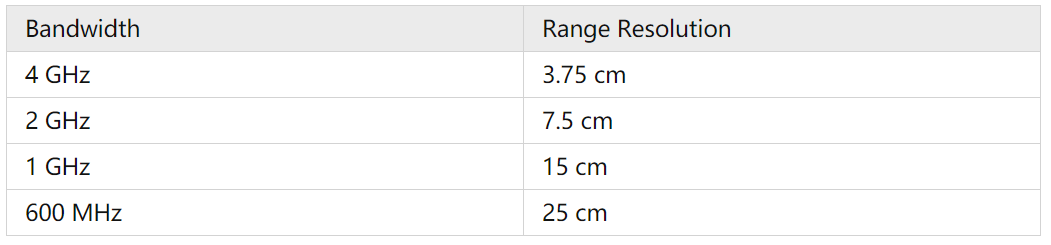
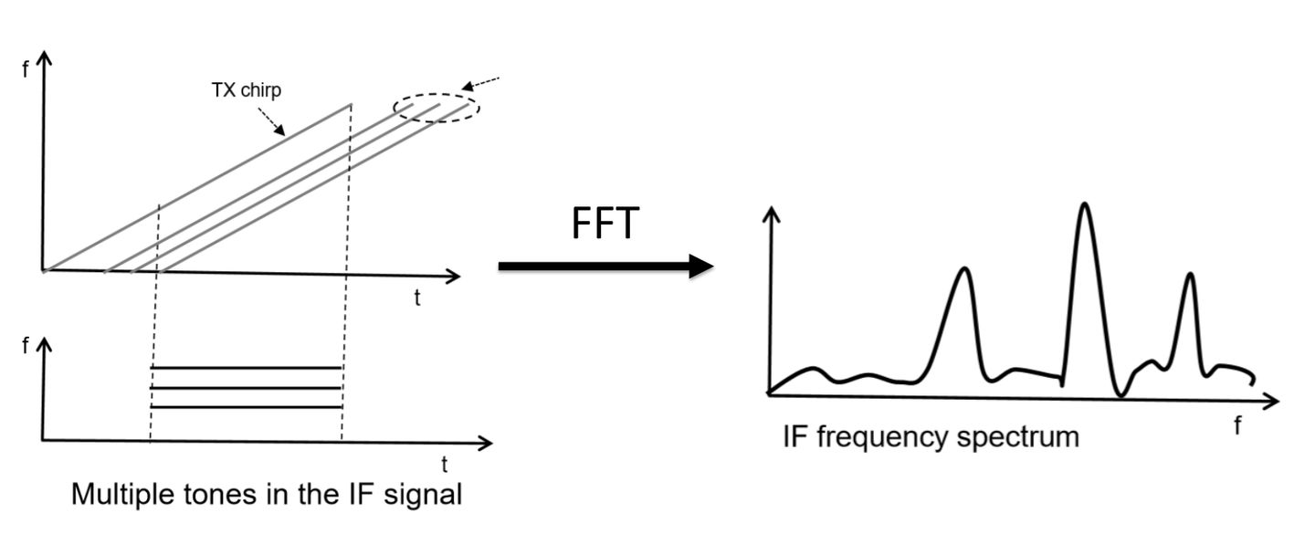
- Multi-target Ranging
If multiple objects’ distances and velocities need to be measured, the frequency of the transmitted signal must be processed accordingly.
After performing the above series of operations, the intersection coordinate map can be obtained:
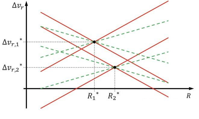
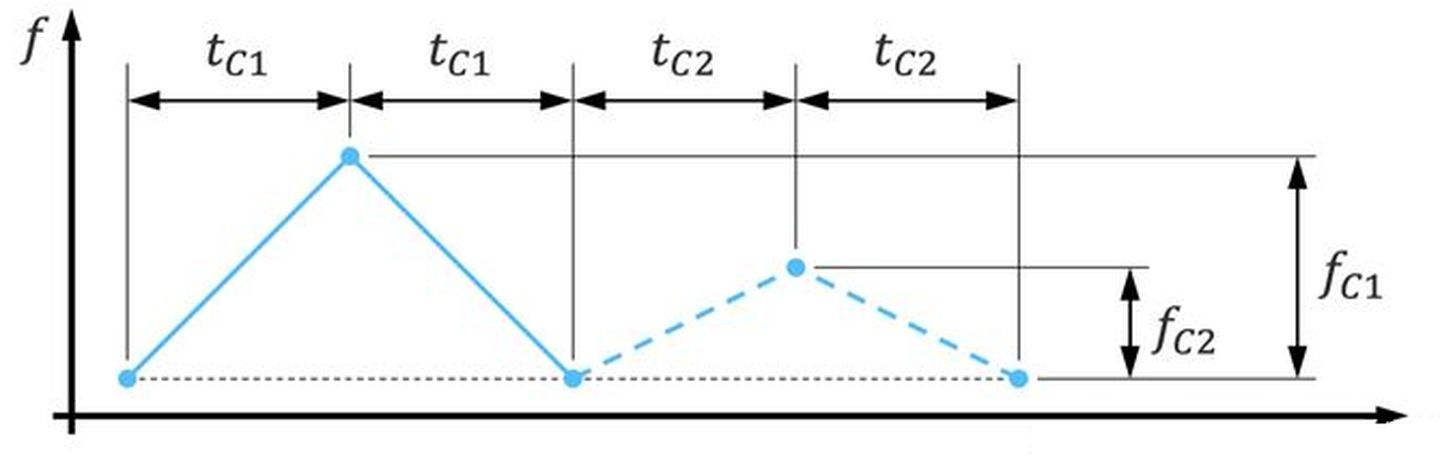
If processing is performed according to the original frequency transformation, four intersections will be obtained (there are four intersections for each of the solid line and the dashed line in the figure), that is, four distances and velocities will be obtained, making it impossible to judge the detected objects.
Changing the bandwidth of the second period of the sweep frequency will result in two common intersections of signals with different sweep frequency bandwidths, thus determining the relative distance and velocity between the two measured objects and the sensor itself.
When receiving different Rx linear frequency modulation waves from different objects, the delay of each linear frequency modulation wave is different, and the delay is proportional to the distance to that object. Different Rx linear frequency modulated pulses are transformed into multiple intermediate frequency signals, each of which has a constant frequency. In practice, to avoid a large number of calculations and improve detection speed and accuracy, one can explore the Fast Chirp Sequence method.
- Maximum Detection Range
 ### Speed Estimation
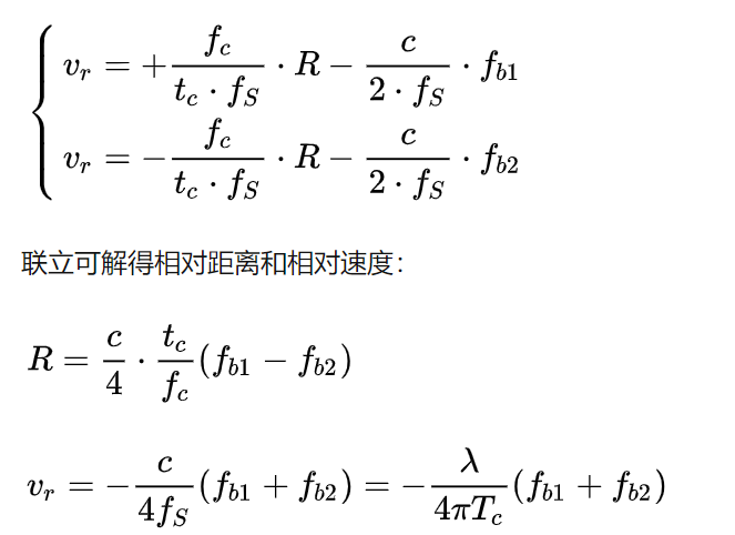
The triangular frequency modulation continuous wave radar eliminates the coupling between distance and velocity by using positive and negative frequency modulation slope, and then estimates the target speed.

To simplify the model and consider the short time delay from signal transmission to reception, constant acceleration, and nearly constant relative velocity of the car, the signal frequency change is shown as follows:
Thus, the relationship between the relative speed vr and the relative distance R is obtained. In order to obtain the specific values of vr and R, the above equation alone is not enough. Therefore, we repeat the operation at the falling edge of the signal frequency, and obtain the following two-element equations:
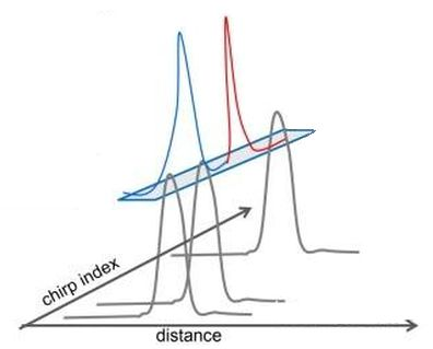
However, in order to obtain the speed information of the target, the radar usually emits a series of chirp signals uniformly and at equal time intervals in frames. Then, the target’s speed in the target field is measured by using the phase difference of the signals. For each chirp, execute distance FFT on the corresponding digital sampling point, and output the result in the form of continuous lines, which is stored in a matrix containing two degrees of freedom of distance and speed.
After the processor receives and processes all single chirps in a frame, it starts to perform Doppler FFT on the chirp sequence.
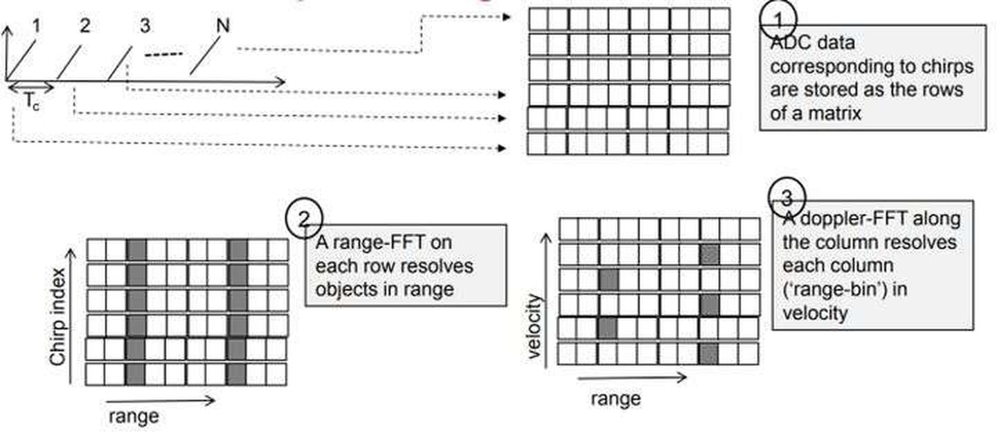
The joint operation of distance FFT (per row) and Doppler FFT (per column) can be visualized as a two-dimensional FFT of digital sampling points corresponding to each frame. The two-dimensional FFT can simultaneously distinguish the distance and velocity of the target. That is to say, the peak position of the two-dimensional FFT corresponds to the distance and velocity of the target in front of the radar.
Multi-Target Speed MeasurementThe bi-linear frequency modulation (LFM) pulse velocity measurement method doesn’t work when using multiple moving objects with different speeds for measurement, but with the same distance from the radar. As these objects have the same medium frequency signal frequency, distance FFT will generate a single peak value representing a merged signal from all the objects having the same distance, and simple phase comparison techniques won’t work.
To measure the speed of multiple targets, the radar system must emit two or more linear frequency modulation pulses. It emits a set of N equally spaced linear frequency modulation signals.
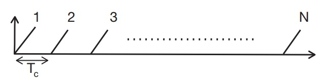
Then, by accumulation, such as one frame that emits 128 chirp signals, each with 128 points. The distance dimension FFT can only calculate its distance value, while to calculate the speed, another FFT must be performed in the velocity dimension.
- Velocity resolution
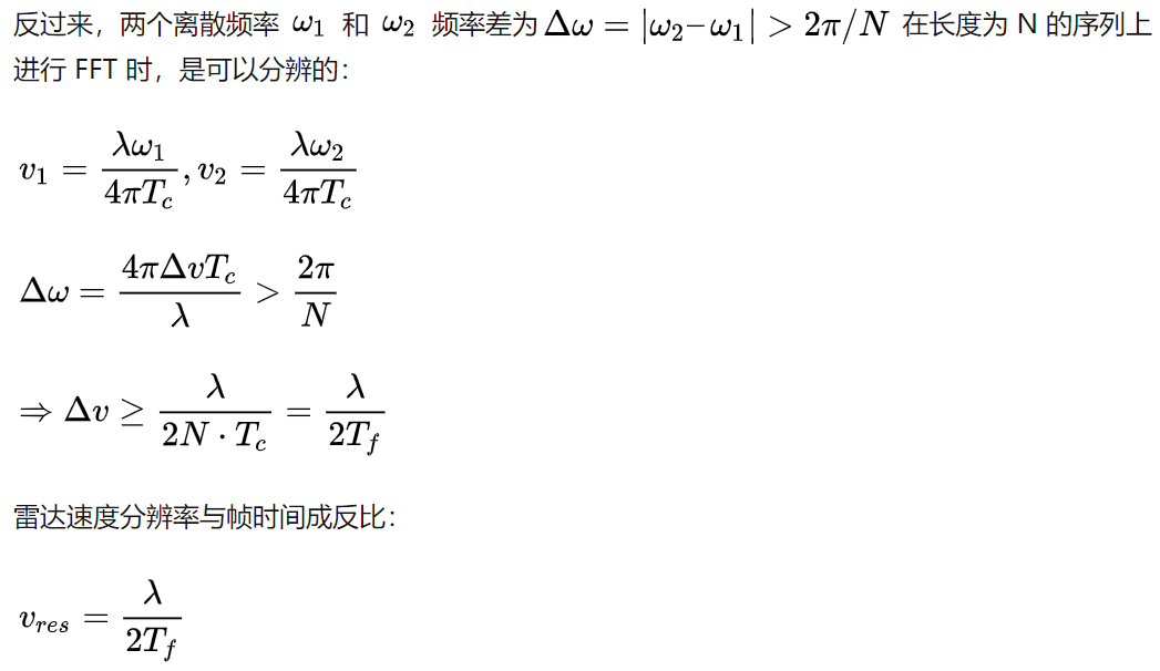
Assuming a series of signals have the same frequency, after FFT, their spectral peak is located in the same position. If there are two different frequency signals, the FFT spectrum will have two peaks. The velocity resolution depends on the number of chirps, but a higher number of chirps require more time to process the signal.
Two discrete frequencies, ω1 and ω2, Δω = π/N. In the N-th signal sequence, the phase of wave 1 lags behind the first signal by half a cycle, which is insufficient to resolve two objects in the frequency domain. In the 2N-th signal sequence, the phase of wave 2 has completed one full cycle, exceeding the phase of wave 1, and thus, two objects can be resolved in the frequency domain. Longer signal sequences can increase the spectral resolution of the signal, which depends on the phase information.
- Maximum unambiguous speed
The maximum unambiguous speed is the maximum measurable speed in simple terms.
According to the formula:
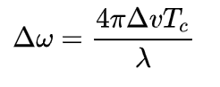
Assuming Tc is constant, as the target’s motion speed increases, Δω increases, but when Δω exceeds π, the radar doesn’t know whether the Δω is the target’s forward motion or backward motion angular frequency, which leads to a dilemma, and thus, requires |Δω| < π:Translate the Chinese Markdown text below into English Markdown text while keeping the HTML tags in a professional manner. Only output the corrected and improved parts without explanation.
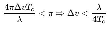
Maximum Unblurred Speed:
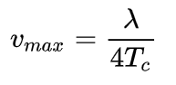
This means that a shorter transmission time between two linear frequency modulation pulses is necessary for a higher measurable maximum speed.
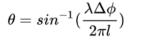
Angle Estimation
FMCW radar systems can use the horizontal plane to estimate the angle of reflected signals, also known as Angle of Arrival.
A small change in the object’s distance can cause a phase change in the peak value of the distance FFT or Doppler FFT, which is used for angle estimation. The resolution of the target angle information requires at least two RX antennas, and angle estimation cannot be performed with a single transmitter or receiver antenna.
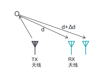
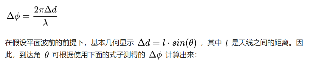
The phase change can be mathematically deduced as follows:

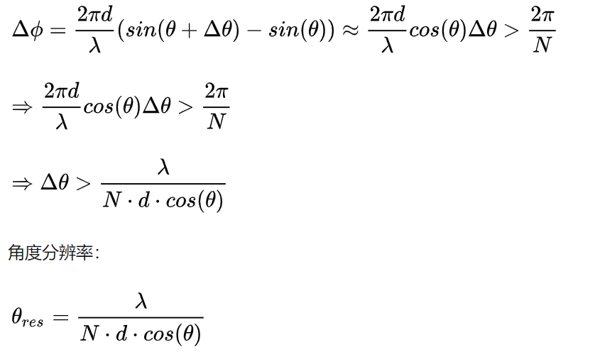
- Angle Resolution
Angle Resolution is the ability of a radar to distinguish between two closely spaced angles in space. Even if two targets are moving at the same distance and speed, they can still be distinguished by their angles in the radar coordinate system. Angle resolution is related to the antenna aperture, signal wavelength, and the number of receiving antennas.
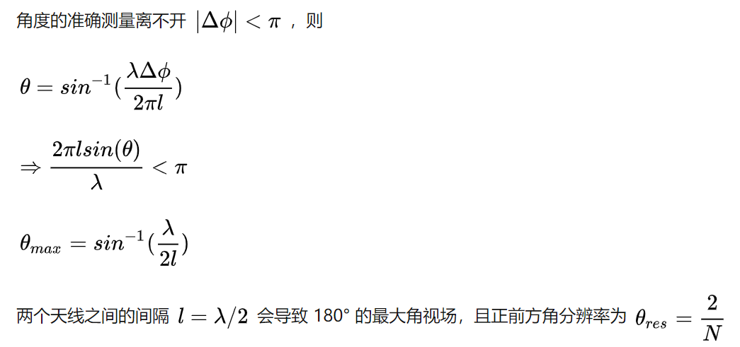
- Maximum Angle of View
Just as there is a maximum detection distance for distance and a maximum unblurred speed for velocity, there is also a maximum detection range for angles, called the maximum angle of view, which is determined by the maximum AoA that can be estimated by the radar.
- MIMO Technology
MIMO radar is an important technology for improving the angular resolution of millimeter-wave radar.# SIMO and MIMO Radars in Automotive Industry
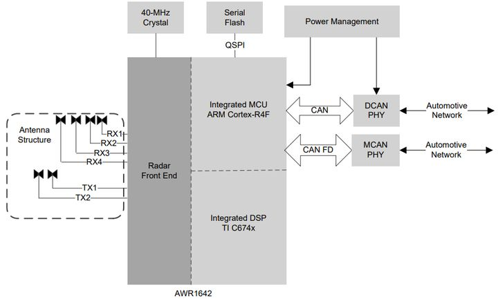
SIMO (Single Input Multiple Output) radar is an equipment equipped with one transmitter and multiple receiver antennas. The angular resolution of SIMO radar depends on the number of receiver antennas. The most direct method to improve angular resolution is to increase the number of receiver antennas. However, this method is limited because each additional receiver antenna requires an independent RX processing chain in the equipment, each equipped with an LNA, mixer, IF filter, and ADC.
MIMO (Multiple Input Multiple Output) radar, on the other hand, has multiple TX and RX antennas, allowing users to generate a virtual antenna array of nTX × nRX. The angular resolution of the MIMO radar with nTX TX antennas and nRX RX antennas is equivalent to that of the SIMO radar with nTX×nRX RX antennas.
By using MIMO radar technology, the number of virtual antennas can be doubled, and the angular resolution can be correspondingly improved. The principle of MIMO radar can be extended to multi-dimensional arrays.
References:
- Wang Fanghao: “A 16,000-word Article Introducing Hardware for Self-Driving Cars”
- William: “Detailed Explanation of Object Detection Technology in Millimeter-Wave Radar [Hardware & Software]”
- Heinrich: “Fourier Analysis Tutorial”
- Wang Tianya: “An Introduction to Autonomous Driving Systems (3) – Millimeter-Wave Radar”
- IEEE1364: “Millimeter-Wave Radar Self-Learning Notes”
- Hongzhu Gongzi: “MIMO Radar Basic Principles”
- Hongzhu Gongzi: “Linear Frequency Modulation Continuous Wave Radar Basic Principles (Part 1)”
- Hongzhu Gongzi: “Linear Frequency Modulation Continuous Wave Radar Basic Principles (Part 2)”
- Hongzhu Gongzi: “Linear Frequency Modulation Continuous Wave Radar Basic Principles (Part 3)”
- “In-Depth Explanation of the Principle and Industrial Chain of Millimeter-Wave Radar”
- “Basic Principles of MIMO Radar to Improve Angular Resolution”
- Ye Rongchaogui: “MIMO Channel Separation in 4D Radar”
- University of Illinois Courseware: “FMCW Radar? Never Heard of it”
- TI Official Website: “Basic Knowledge of Millimeter-Wave Sensors”
- TI Research on Hardware Architecture of Single-Chip Millimeter-Wave Radar IWR1642
- TI Official Website: “AWR1843 Single-Chip 77GHz and 79GHz FMCW Radar Sensors”
- TI Official Website: “xWR1843 Evaluation Module (xWR1843BOOST) Single-Chip – mmWave Sensing Solution”
- Oxford Radar RobotCar Dataset.
This article is a translation by ChatGPT of a Chinese report from 42HOW. If you have any questions about it, please email bd@42how.com.