Up until now, the share of the entry-level hardware for autonomous driving technology has been completed.
Next, I will share more content related to software.
The main topic of this issue is the Controller Area Network (CAN) bus in autonomous driving.
The CAN bus plays a very important role in the entire autonomous driving system. In addition to the VCU signal mentioned in “Introduction to Autonomous Driving Technology (Part 9) – VCU Signal“, which needs to be transmitted through the CAN bus, some sensors on the autonomous vehicle (such as radar and Mobileye) also transmit signals through CAN.
As I mentioned in “How to Research Autonomous Driving for Individuals?”.
To implement an autonomous driving system, there are several levels:
Perception layer -> Fusion layer -> Planning layer -> Control layer.
More specifically:
Sensor layer -> Drive layer -> Information fusion layer -> Decision planning layer -> Lower control layer.
The “sensor layer” has been introduced in the first ten issues of the technical entry-level sharing. This time, I will mainly introduce the content related to the “drive layer”.
CAN communication is a high-performance and highly reliable communication mechanism, which is currently widely used in the field of automotive electronics. The principle and characteristics of the CAN bus are not the focus of this sharing. The focus of this article is how to parse the desired data based on the CAN protocol after the autonomous driving system receives the CAN message. Parsing the information of the sensors from the CAN bus can be said to be a necessary skill for every autonomous driving engineer and even every automotive electronics engineer.
Understanding CAN Messages
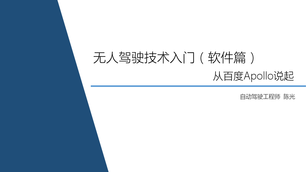
Taking the open-source code Apollo launched by Baidu as an example to explain the CAN messages, let’s first see how each frame of the CAN message is defined.
It can be seen that the CanFrame message structure contains four key pieces of information, which are:
1. uint32_t id
The ID number of the CAN message.Due to the transmission of numerous CAN messages on the CAN bus, when two nodes communicate, they first look at the id number to ensure that this is the CAN message the node wants. The original range of CAN message id numbers is 000-7FF (hexadecimal), but as the number of automotive electronic control signals increases and the number of messages that need to be transmitted increases, the information is not enough. Engineers have extended the range of id numbers on the basis of CAN messages, greatly increasing the upper limit of id numbers, and the improved CAN message is called “extended frame”, while the old version of CAN message is called “standard frame”.
If we compare it to writing a letter, this id is somewhat similar to the name written on the envelope.
2. uint8_t len
The effective length of the CAN message.
Each frame of the CAN message can transmit up to 8 unsigned integer data or 8*8 boolean data. The maximum value of len here is 8. If there is no data in some bits of the CAN message frame, len here will be less than 8.
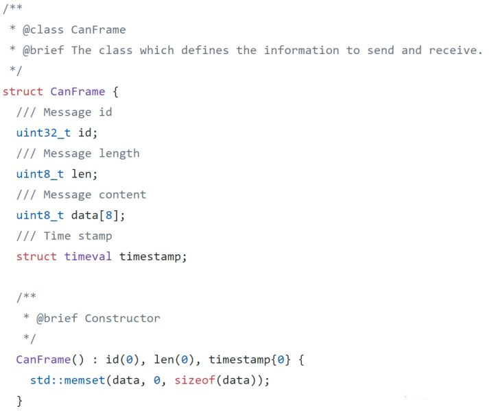
3. uint8_t data [8]
The actual data of the CAN message.
As mentioned earlier, each frame of the CAN message contains up to 88 boolean data. Therefore, the data in the CAN message can be visualized through 88 squares as shown in the figure below.
Without the help of the CAN protocol to parse the data, the data here is no different from gibberish, and it is impossible to obtain useful messages, which is one of the reasons why CAN message is difficult to crack.
4. timestamp
The timestamp of the CAN message.
The timestamp represents the moment when the CAN message is received. By continuously obtaining the timestamps of multiple frames, the sending cycle of the CAN message can be calculated, which can also be used to determine whether the CAN message has been continuously received.
Therefore, the most important part of each CAN message is actually bata, which is the 88 boolean values. The so-called parsing of CAN messages is actually the parsing of these 88 boolean values.
Understanding of CAN Protocol
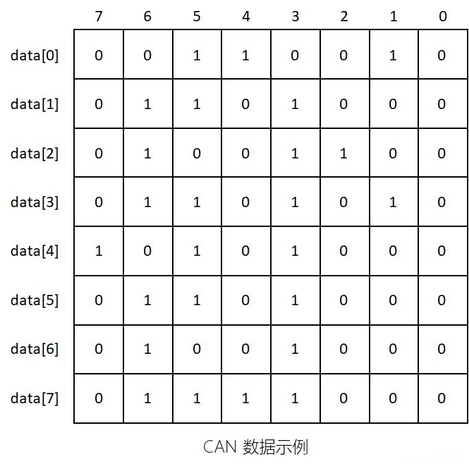
Currently, the CAN protocol in the industry is stored in files with the suffix “.dbc”. The CANdb++Editor provided by the German company Vector is a software specifically used to read dbc files.
As shown in the figure below, the dbc file for lane lines provided by Mobileye is displayed.
Taking LKALeftLane_A with ID 0x766 as an example, this is part of the information that Mobileye detects the left lane of autonomous vehicles, including the offset and curvature of the left lane.
The five signals (Signal) in this CAN message are LaneType, Quality, Curvature, CurvatureDerivative, Widthleftmarking, and Position.
The specific descriptions of each signal are displayed on the right side of the software. Three elements directly related to parsing are highlighted in green boxes.
- Value Type (Unsigned or Signed)
Some physical quantities are described with signs, such as temperature. While other quantities are described without signs, which are all positive, such as curvature.
- Factor and Offset
These two parameters need to be used in actual physical calculations. Factor is the multiplier, and Offset is the deviation. For instance, the Factor of Lane_Type and Quality signals is 1, with Offset 0, while the Factor for other signals is a decimal. The specific calculation method is shown below.
Double-click LKALeftLane_A to open the Layout page, where you will find a familiar block array, as shown in the figure below.
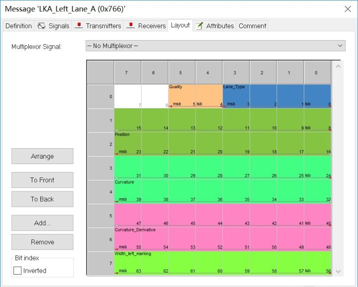
Engineers are truly interested in this colorful picture because each small square on the picture corresponds to each bool quantity in the data. This is the true appearance of the CAN protocol.
Parsing CAN Signals
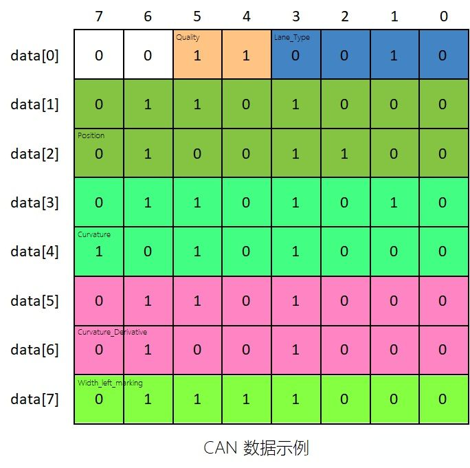
Since the colored block diagram corresponds to the data one by one, we overlay the two graphs to obtain the data graph shown below.
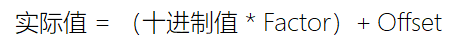
The calculation formula for each signal’s physical quantity is shown as follows:
 1. Physics Quantity with Factor of 1
Because the factors of LaneType and Quality are 1, and the offsets are 0, the actual physical quantity is equal to its decimal value. From the graph, we can see that the Quality signal occupies two bits, which is binary 11, equivalent to decimal 3 (2^1 + 1^1); LaneType occupies four bits, which is binary 0010, equivalent to decimal 2 (0^8 + 0^4 + 1^2 + 0^1). Therefore, this signal frame represents a Lane_Type value of 2 and a Quality value of 3. For integer values, communication partners can agree on rules, such as Mobileye, which has established that when Quality is 0 or 1, the confidence level of the lane line is low and should not be used, while 2 represents medium confidence level, and 3 represents high confidence level, which can be used with confidence.
2. Physics Quantity with Decimal Factor
For physical quantities with factors other than 1, such as Position, shifting is used to decode them, yet the decoding formula remains unchanged. Taking the source code provided by Baidu Apollo as an example, bytes here refer to the data in the CAN message. First, the row where the Position signal is located is taken out, with the 8 bool values in the first row stored in the variable t1, and the 8 bool values in the second row stored in the variable t0. Since in this CAN message, Position occupies both the high 8 bits and the low 8 bits, all the bool bits in both the first and the second rows need to be calculated, with the high 8 bits stored in a 32-bit variable x and the low 8 bits stored in another 32-bit variable t.
Now, it is necessary to concatenate the high 8 bits with the low 8 bits, shift the high 8 bits to the left by 8 bits, and then perform a bitwise OR operation with the low 8 bits to obtain the binary value of Position. The subsequent operation of shifting left by 16 bits and right by 16 bits is to initialize all the high 16 bits of the 32-bit variable x to 0. Next, multiply x by the Factor and add the Offset to obtain the true Position value, which can be represented in meters for the actual physical quantity.
Communication Protocol Similar to CANVCU, radars, and other devices transmit signals via CAN bus. As the load on the CAN bus increases, many sensors have chosen to use other communication methods. For example, laser radar has too much point cloud data and uses local area network to transmit data. Another example is GPS and inertial navigation systems, which use serial ports for communication.
Although communication methods and protocols vary widely, the parsing methods are all the same.
Conclusion
Well, this article has basically explained the process of parsing CAN bus messages. This is the basic theory of the sensor driver layer in the unmanned driving system.
Since the structure of CAN messages with different IDs are different, great care must be taken when writing parsing code, otherwise unexpected bugs may occur in subsequent processing.
If you have any questions about parsing CAN bus messages, feel free to interact with me in the comments section.
This article is a translation by ChatGPT of a Chinese report from 42HOW. If you have any questions about it, please email bd@42how.com.