Introduction
Today is Saturday, and I’m here to continue analyzing the hardware of automotive electronics. This time, we will focus on the first-generation liquid crystal instrument panel for Audi, developed by Bosch. The 12.3-inch screen (1440 * 540 IPS LCD) also incorporates the concept of virtual driving. The processor used is NVIDIA Tegra 3, with a peile ROM of 4 GB + 64 MB and an 8 MB RAM. The operating system adopted is QNX.
Part One: Disassembly Structural Diagram
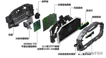
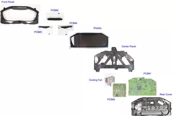
As shown in the figure below, Audi uses many boards to make this instrument panel, consisting of six display areas and using five PCB boards for display.
PCB1: 185.0 x 121.3 x 1.70 mm, the main control board for the instrument panel circuit.
PCB2: 85.12 x 85.01 x 1.24 mm, NVIDIA T30 graphics processing board.
PCB3: 138.56 x 23.07 x 1.74, warning light LED driver board.
PCB4: 113.67 x 20.50 x 1.70, barcode display module.
PCB5: 113.63 x 20.65 x 1.58, cooling temperature barcode module.
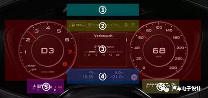
The division of the LCD display is more detailed and includes six areas in general:
Area ① is the traditional warning light, including turn signal indication, oil warning, handbrake reminder, etc.
Area ② is the common function prompt area, including fuel endurance mileage, radio frequency band tuning, etc.
Area ③ is the central main display screen, including speedometer and tachometer, as well as all empty capabilities of the MMI system will be displayed here.
Area ④ is also a functional prompt area, including reminders for unfastened seatbelts, speed limit reminders, etc.
Areas ⑤ and ⑥ are virtual displays for water temperature and fuel level.
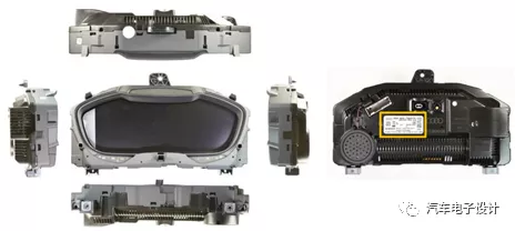
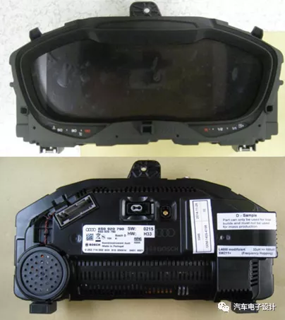
As shown in the following figure, this is an overview of the internal photo. Next, we will further disassemble the entire instrument panel, which has dimensions of 323 x 190 x 87 mm and weighs 1.6 kg.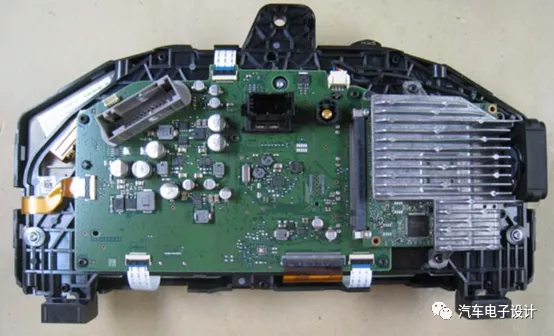
Part 2 Disassembly of Several Boards
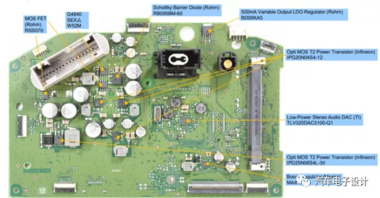
There are mainly two large boards. This is the front of the main control board, which is mainly composed of connectors and power chips. SEX W52M MOS FET (Rohm)
RSS070 Schottky diode (Rohm)
RB095BM mA output LDO (Rohm)
BD00KA5 Opti MOS T2 transistor (Infineon)
IPG20N04S4-12 high-performance 3D sound
DAC (TI) TLV320DAC3100-Q1
Opti MOS T2 transistor (Infineon)
IPD25N06S4L-30 pressure regulator MAX
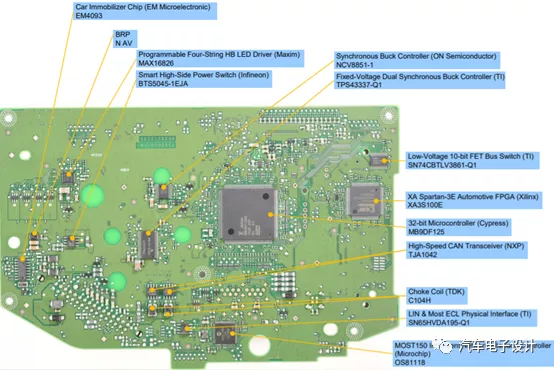
The front of the main board includes an anti-theft module (EM Microelectronic) EM 4093
Editable HB LED driver MAX16826
Smart high-side switch (Infineon) BTS5045-1EJA
Synchronous Buck circuit (ON Semiconductor) NCV8851-1
Fixed voltage Buck controller (TI) TPS43337-Q1
XA Spartan-3E FPGA (Xilinx) XA3S100E
32-bit MCU controller (Cypress) MB9DF125
LIN and MOST controllers (TI) TISN65HVDA195-Q1
MOST150 intelligent network controller (Microchip) OS81118
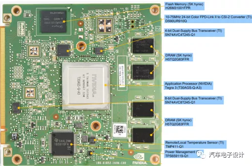
Nvidia’s board is connected by a slot, which is consistent with our previous understanding of industrial motherboards. In fact, this structure may become popular in future in-vehicle computers.
SK hynix H26M31001FPR“`
10-75MHz 24-bit FPD-LinkII to CSI-2 Converter (TI) DS90UR910Q
DRAM (SK hynix) H5TQ2G83FFR
NVIDIA Tegra 3 (T30AGS-Q-A3)
DRAM (SK hynix) H5TQ2G83FFR
Power Management (TI) TPS Q1
Summary
In fact, earlier virtual cockpits had several screens that were individually designed with complex hardware and systems. As consumers hope to further integrate the functions of these components, the hardware becomes more like a host, and the software that overlays the partitioned display becomes more critical.
“`
This article is a translation by ChatGPT of a Chinese report from 42HOW. If you have any questions about it, please email bd@42how.com.