Introduction
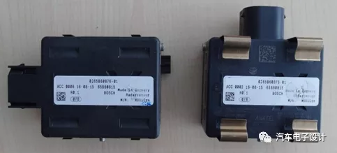
Continuing with the hardware teardown work on Saturday, today I took apart a 77 GHz millimeter-wave radar from MRR for analysis. The working principle of millimeter-wave radar is to emit millimeter waves outward via the antenna, and receive target reflection signals. After comparing and processing the signals, the final classification and identification of the target is achieved.
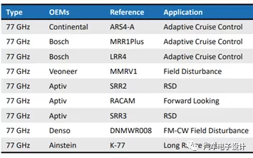
Unlike lidar, the pricing of this component is determined by the pricing strategy of the main Tie1 companies. In fact, the survival space for domestic manufacturers of this component is very narrow. Note: System Plus has dismantled Mando’s MRR 20, Denso’s DNMWR 009 and Bosch’s MRR1 radar. Interested readers can check them out.
Structure of Millimeter-wave Radar
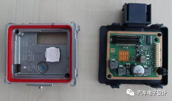
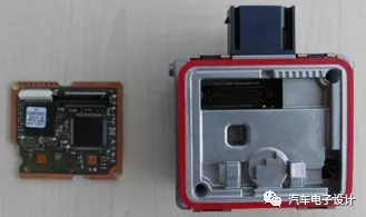
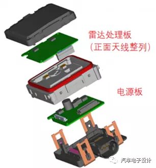
First, let’s take a look at a set of teardown structure diagrams, and then break down a few parts. This radar mainly consists of two PCB boards and other components:
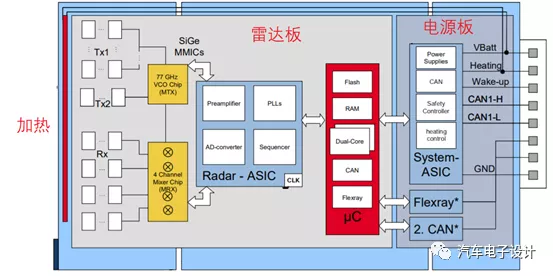
1) Power PCB board provides ASIC chips that supply all internal voltages for the radar. The chip integrates a safety controller (with watchdog function and CAN interface).
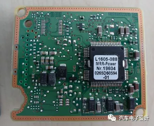
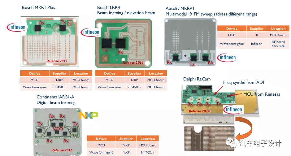
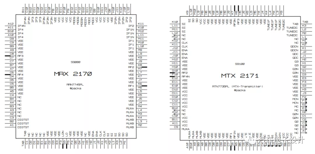
2) Millimeter-wave radar PCB, as shown in the following figure, mainly includes a dual-core floating-point MCU and a Radar ASIC chip, with an independent front-end amplifier that can be controlled and self-diagnosed, SiGe MMIC unit and PLL unit, and a SiGe ASIC (MRX) with four mixers for signal reception.
Note: The front-end transceiver component MMIC is the core part of millimeter-wave radar, responsible for modulation, transmission, reception and demodulation of millimeter-wave signals. The transceiver component includes multiple electronic components such as amplifiers, oscillators, switches, and mixers.
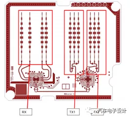
 The back of the millimeter wave radar PCB is an antenna used for transmitting and receiving millimeter waves. As shown in the figure below, a microstrip array is laid on the printed circuit PCB, forming a microstrip patch antenna. TX is 15.7 dBi and RX is 13dBi.
Functional Description
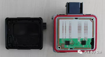
There is a detailed description in the MRR1Crn technical description, and the exploded view of the radar is shown below:
The main functional structures include:
In front of the antenna array, there is a plastic cover of Radam, which not only considers the microwave transmission effect in the design but also includes a heating wire. It is controlled by the power board to ensure work in extreme environments.
Conclusion
In the future, most of the components in vehicles will tend to be wireless, driven by the cost of chips + process + added value brought by some special know-how. As the millimeter wave radar market in the future is also concentrated in a few large manufacturers, theoretically, there is not much market space.
From a safety perspective, this component belongs to the core part of collision prevention system and requires very high functional safety. Such a high degree of integration of several components cannot be held by ordinary enterprises.
This article is a translation by ChatGPT of a Chinese report from 42HOW. If you have any questions about it, please email bd@42how.com.