This article is reproduced from the WeChat public account “Cool Winter Melon”. Please contact the author for reprinting.
In the last article, we mentioned the existence of this article at the end.
It has been more than ten days in the blink of an eye. During this period, some friends have come to me to consult some things, prepared some materials for a few friends who are doing industry research, and also did some analysis and preparation for the data needed for the article. I feel that time passed quickly and slowly at my hometown. By the way, let me share some news: after this month, I will be officially unemployed… Thinking about it makes me a little excited.
Okay, let’s get back on track.
Today we mainly have two topics. One is the “Communication Architecture” (network topology) of Tesla Model 3. We have made new discoveries. Another is the demonstration of the phased achievement of “cracking” the bus signal of Model 3, which we have been “researching” for a long time. This is also a “starting point” and we hope that more people will participate in “understanding” Tesla’s “design code”.
Let’s describe them one by one.
New discovery of Model 3 Communication Architecture
This new discovery is actually a supplement to the previously organized network topology- sorry, this “Communication Architecture” is temporarily inconvenient to be placed in the article. If you are interested, you can communicate according to the prompts at the end of the article- we first attach the topology map organized based on the principle diagram.
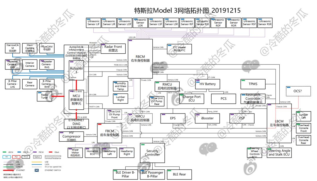
Tesla Model 3 network topology diagram_20191215
What has been added?
1. The internal principles of the “Enclosure” of several core controllers
Including BCM Left/Right, Autopilot+MCU (Media), HVC (High Voltage Controller), EPS, etc., the most typical of which is the BCM Right that connects the ultrasonic radar- forcibly “Single Enclosure.” According to these principles, Tesla’s design ideas can be clearly understood.
2. It is clear that controllers in the same network segment with the same occupation of different pins are a “fact”
Some may not understand what I’m about to say, so you can first take a look at the illustration below:

Schematic of network connection for Tesla Model 3 right body controller
This type of connection method cannot be distinguished based on the principles of the entire vehicle alone – as they occupy different pins but are also on the same network segment. This can be confirmed in the message records in Chapter 2. Tesla is “always happy” with this design, which is essentially to place the harness pin in the ECU board to consider the partitioning of the harness.
3. Defined the wake-up behavior of different nodes and distinguished “Powered during vehicle sleep”
This is what a systems engineer should do, and it is very convenient to reflect in the topology diagram.
Tesla didn’t bring up anything about network management, just telling you that “this node on this network segment needs network wake-up”, “that node still needs power supply during idle state of the whole vehicle”, and straight to the heart of the problem.
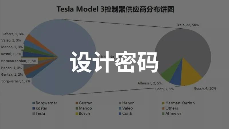
4. Indicated the supplier of the controller
Here, I have made a simple summary.

The distribution pie chart of Tesla Model 3 controller suppliers.
According to the incomplete statistics in the above figure, Tesla’s self-developed controllers occupy the most. Initially, it was just the self-developed core of the three-electricity, central control, and AP. Now, even low-threshold body controllers are not let go (of course, there are other relatively important ones, such as the Security Controller), which is crazy!
Unless there are two trump cards (mastering the core technology), the days of controller suppliers will not be easy.
5. Of course, there are also details remaining, such as the design of terminal nodes and optional node design.
Model 3 bus signal cracking
In fact, we have also cracked Model S/X, but one is too old (two years?) and the other is the hot new Model 3, which deserves its glory.
Before we start, let’s take a look at the background in previous articles.> Private CAN (i.e. PARTY CAN) connects steering, braking, and chassis modules to driving modules, AP, and vehicle control functions. It is speculated that this is the most basic and important module for information exchange related to driving and chassis control. To put it simply, it is difficult to access this route without disassembling the car.
Vehicle CAN connects the three major body control modules, high-voltage management modules, and VSC (Security Controller). It is mainly responsible for traditional body domain functions (load control, air conditioning, entry and exit) and high-voltage management. This route is also the most accessible without disassembling the car.
Chassis CAN is relatively traditional and connects braking, steering, airbags, and other functions.
From the pin definitions of the controllers, we introduce the allocation of functions of Tesla Model 3. More information can be found in the article by 冷酷的冬瓜 on WeChat Official Account “冷酷的冬瓜”.
This article focuses on Vehicle CAN, and the data is based on the Model 3 imported LR RWD V10.2 (2019.40.50.7).
Previous experiences of “introducing bus design” were lacking, so I propose two aspects to discuss: an overview of the overall situation and data presentation of typical working conditions. For more professional interpretation or requirements, please communicate according to the prompt at the end of the article.
1. Overview of Model 3 Vehicle CAN
(1) The ID distribution ranges from 0x0C to 0x7FF (without sending diagnostic requests), with a total of 280 frames.
Feel like there are still a lot of frame numbers (I don’t have a lot of concept, someone who works on network design can talk about it), and there are signals as numerous as hairs on an ox. We will later see the signal situation obtained from the cracking.
(2) The minimum and maximum load rates of this network segment are 38% and 55% respectively, and the average can reach 49%!

Tesla Model 3 Vehicle CAN load rate status (normal driving conditions on winter nights)
Make the most of everything, and everything has not been utilized to the fullest!
(3) According to the cracked information, Model 3 uses a lot of multiplexing types, such as state quantities that do not require high real-time performance. The “current” fault status corresponding to each node and DTC—I personally speculate that the data used by the background is to obtain the status of the vehicle in real time rather than diagnostic requests, as well as the structured node message frame structure, see the figure below for details.
Where alertMatrix is the current fault bit, info includes the version/production and other track information, and status and ECU node system status information.

Tesla Model 3 Vehicle CAN EPB Left sends message matrix diagram
(4) The degree of cracking is 66.4% (186 fr/280 fr), and the matching analysis of a client’s signal requirement that needs “deep benchmarking on Tesla Model 3” is shown in the figure below.
Overall, the information that can be used is quite abundant.
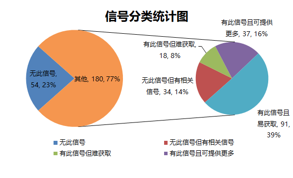
Pie chart of matching degree of a client’s signal requirement in Tesla Model 3 Vehicle CAN bus cracking
Note:
-
No such signal: no corresponding signal was found, such as “12V battery SOC”;
-
There is no corresponding signal, but there are related signals: there is no unique signal corresponding, but the desired signal can be indirectly obtained through other signals, such as “BMS fault level” is not available, but there are many alerts (presumably corresponding to the current fault status of DTC), which can be referenced.“`
-
Signal Available but Difficult to Obtain: There is a signal definition, but it is not easily accessible from the Vehicle CAN listener, such as the wheel speed signal;
-
Signal Available and More Can Be Provided: There is a corresponding signal, and more information can be provided, such as the “gear position,” which not only has the logic gear of the whole vehicle, but also the physical state of the shift lever;
-
Signal Available and Easy to Obtain: There is a corresponding signal and it is on the Vehicle CAN, such as the vast majority of signals.
2. Typical Operating Conditions
Believe that those who really do system/performance/testing will design more professional use cases to explore more information. Here we only provide typical operating conditions. Known signals include but are not limited to:
- Vehicle status (driving behavior, parking, pedals, mileage, etc.);
- Motor+inverter (speed, torque, temperature, etc.);
- Battery (bus voltage, current, SOC, discharging capabilities, cell status such as voltage, temperature, consistency, etc.);
- High-voltage accessory status (DCDC/OBC, etc.);
- HVAC+Thermal management of air conditioning assembly;
- Others (such as BCM Left/Right/Front for vehicle comfort).
(1) The vehicle is stationary and the central control screen is operated.

Data recording graphic of the stationary vehicle and the central control screen operation.
(2) The vehicle is stationary and the air conditioner is operated.
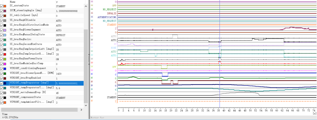
Data recording graphic of the stationary vehicle and the air conditioner operation.
(3) The vehicle is driving normally (including turning).
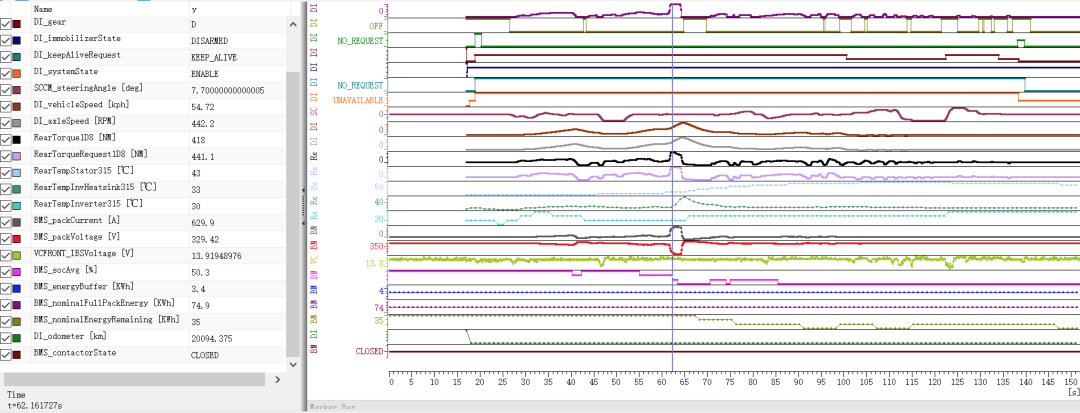
Data recording graphic of the vehicle driving normally (including turning).
(4) Slow charging.
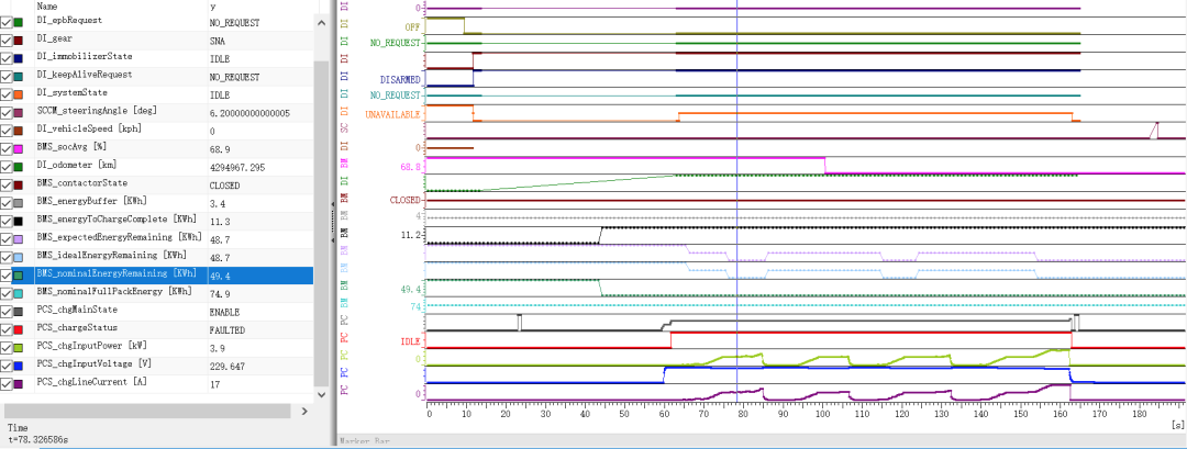
Data recording graphic of the stationary vehicle and slow charging.
“`Please provide the original text in Markdown with HTML tags and I will translate it into English.
This article is a translation by ChatGPT of a Chinese report from 42HOW. If you have any questions about it, please email bd@42how.com.