As an engineer who worked at General Motors for nearly 7 years, I divided GM’s past electrification strategies into several phases.
Ancient Phase: Start the development of EV1
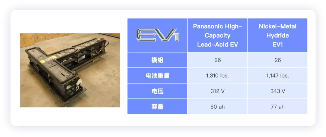
My counterparts at that time were lucky enough to become senior engineers at Level 8, who experienced the most glorious period for GM. Although this batch of cars was reclaimed and destroyed, the most remarkable feature of this period was that many new technologies were attempted, and lead-acid batteries were used for the battery.
First Exploration Phase (2010-2014):
Develop around the Volt and BEV1 models at the same time. Volt and LG developed PHEV batteries, while BEV1 and A123 developed LFP batteries. This phase was a massive offensive supported by the Obama administration in the United States, focusing on the development of PHEVs, and the entire battery system was almost completed based on the previous T-type battery system. On the BEV, customizing the rear axle based on the Spark model.
Second Repeating Phase (2014-2016):
In this phase, Volt Gen2 was developed, and HEV was developed on Volt Gen2, and P1P4 was planned for the hybrid system. In BEV2, Bolt EV was developed and positioned it as a strategic model with a benchmark of Model 3 at 35,000 US dollars. The battery pack of this BEV2 was initially designed by LG Chem, then took over, and there were also 100miles and 200miles to choose from in the middle, finally leaving 200miles, which is what everyone saw.
Gap Year (2017-2018):
During this phase, it was a period of confusion due to the lack of development focus in North America. This was also the stage when I left. In the planning stage of 2016-2020, this was a response to the gap period.
Third Phase (After 2019):
At this time, GM began to fully develop BEV3 and planned for the Ultium platform.
 The domestically-used battery cells are from Fangkuai with the choice of ternary route in China. As the energy density of battery cells increases, the thermal protection mainly consists of the following three parts:
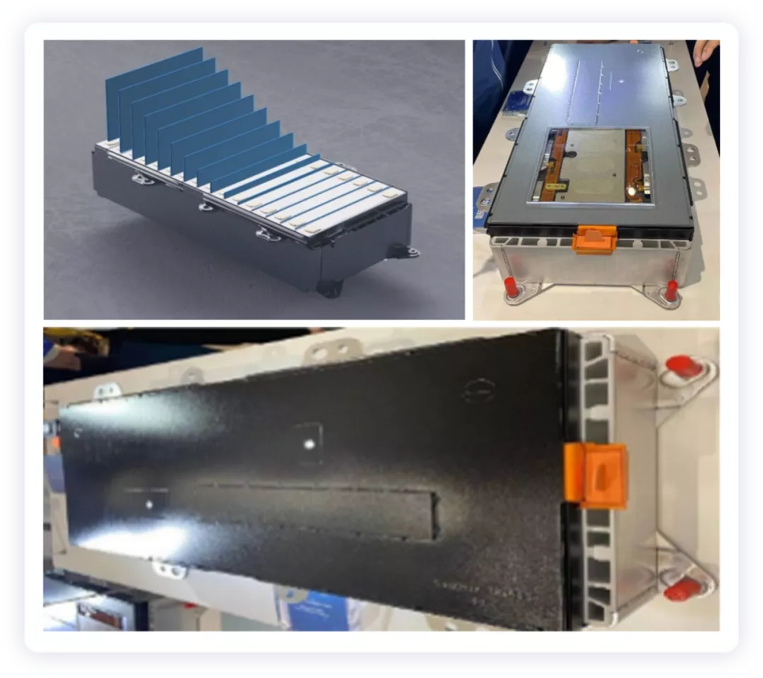
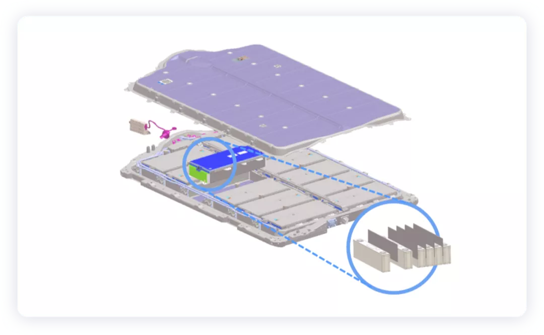
1) Insulation materials are used for protection between each battery cell.
2) Mica sheets are used to block above the pressure relief valves of the battery cells, so the battery module cover is still made of plastic.
3) Integrated cooling can also help the battery cells enhance heat dissipation in normal and thermal runaway states.
The latest details include:
● The positive electrode material of the battery cell uses in-situ coating, which improves its thermal stability by 10% compared to the original NCM811. The chemical system is a ternary positive electrode matched with high-capacity graphite negative electrode (355mAh/g).
Note: I guess this is also a Ni 55 chemical system.

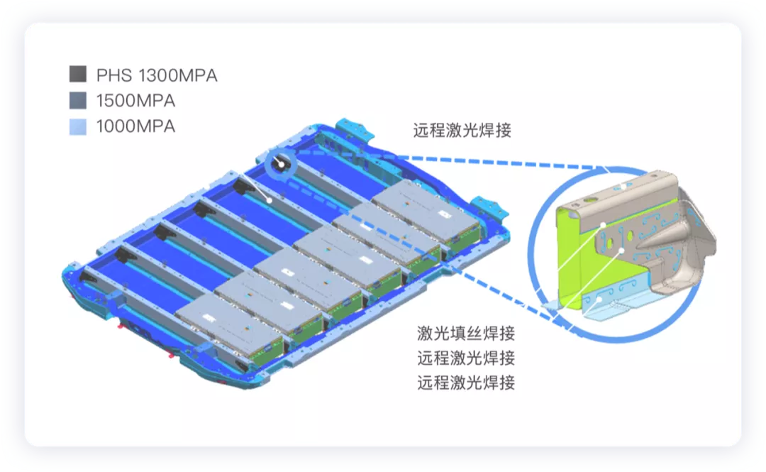
● This battery pack is probably the most crash-resistant one. Multiple 1500MPA ultra-high-strength steel beams are used for reinforcement inside the battery pack (5 beams in 12 modules, 4 beams in 10 modules, and 3 beams in 8 modules).
The upper cover assembly adopts 1500MPA ultra-strong side protection beams, and the pallet assembly uses 1000MPA bottom protection. In other words, the battery shell is particularly heavy.
● Thicker aerogel is used for fire isolation between the battery cells. The built-in aerogel fire blanket is installed inside the battery module cover. The battery pack is equipped with a large-area explosion-proof system with a unique exhaust passage, which can quickly discharge high-temperature gas.

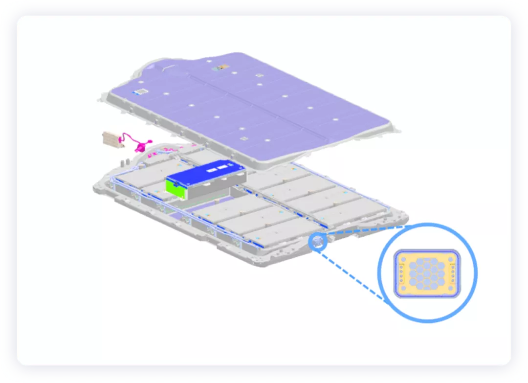
● At the thermal management level, an integrated independent liquid cooling plate is configured for each module. The high-voltage components inside the battery pack have an arc-prevention design after the thermal runaway of the cell.

Of course, the biggest highlight of this system is the world’s first wireless battery management system in a passenger car, which also reduces 90% of the wiring harnesses in the battery system and constrains a large number of sampling cables in the module segment. The battery cells are mainly monitored by three parameters: air pressure, battery temperature, and battery voltage. Cooling measures will be taken immediately when a problem is identified.
In conclusion, I think that for safety reasons, the square shell battery has achieved what most others have achieved, which is slightly dull.
This article is a translation by ChatGPT of a Chinese report from 42HOW. If you have any questions about it, please email bd@42how.com.