Ingineerix, a guru on YouTube, dissected and commented on the battery and power systems of the Model S Plaid. I will summarize the contents in two parts. Due to the unremovable module, the available information mainly includes the design concept and electrical design of the overall module structure. The design is expected to reach an upgraded capacity of 400V+*900A in the future, taking a high-current route.
The dissection analysis video of Model S Plaid (Ingineerix) has been posted on the knowledge planet.
Battery Module Design
The battery system is divided into five areas, which seems to transition from the large module to complete adhesion with the system based on the current design.
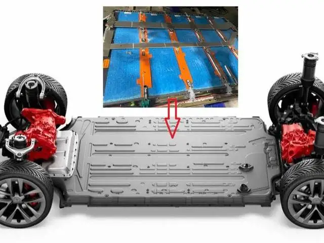
The positive and negative poles of these five large battery blocks are arranged on two long sides and connected by busbar welding. The module is configured with 22S72P battery cells, and the entire battery system reaches 110S72P, which increases the overall voltage and rated voltage to 401V. According to preliminary calculations, there are approximately 7920 18650 cells from Panasonic with improved energy density. The module size is currently unclear, but it extends along the width direction and is approximately 1.3-1.4m.
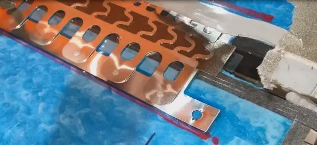
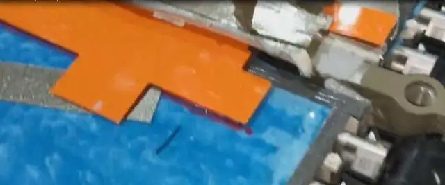 In the design of the busbar on this side of the module edge, there is an interesting feature: a degree of fusing protection. I think this is key to Tesla’s effective use of Pyrofuse. If functional safety requirements are relatively high relying only on Pyrofuse, then utilizing physical fusing protection at both the cell and module levels achieves redundancy at different levels.
Currently, like the Model Y’s 4680, Tesla has made the BMS sampling board CMU into a long strip and integrated it into the module. It is also fixed to the end plate through structural components and glue, directly connected to the PCB board through the busbar pins between the cells. This is almost identical.
Electrical Design
In the layout of the entire pack, the Model S Plaid was designed as a high-performance model from the beginning, so it needed to be designed towards a four-wheel drive direction, with new features in electrical design.
It is divided into two parts here:
BDU, BMS, and fuses: they are placed in the front with Pyrofuse designed as a maintenance window as the front BDU;
Combination of contactors: Master positive, master negative, and two twin fast charging contactors are placed in the back of the battery system, with a maintenance window designed to handle it from under the seat.
Tesla ingeniously uses two huge long busbars to connect these two BDUs.
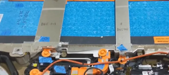
One thing to note is that more and more automakers are beginning to implement half-voltage protection, which means that the main fuses are placed in the middle where the large modules are connected. There is a detailed calculation process for designing half-voltage protective measures. I have carefully calculated it, and I will share the calculation process when I have time.
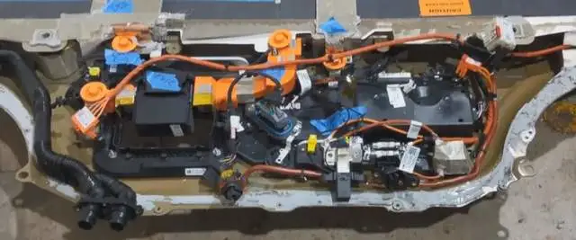
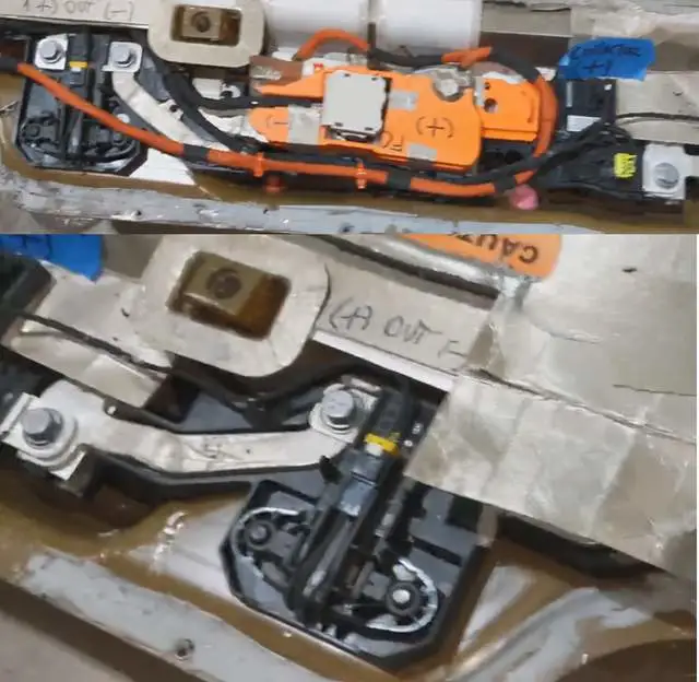 From the specifications gathered from the supply chain feedback, Tesla’s target is to continuously increase the charging current, with the goal of raising it to 900A or even higher in the future. Therefore, in the entire electrical design, protective components involved in the charging circuit have been improved, making this Pyrofuse bigger than before. On the one hand, it needs a larger arc extinction area, and on the other hand, it improves the historical design issues.
Note: Getting to know the actual principles and experimental information from the device suppliers is still an effective method.
Due to the introduction of heat pumps throughout the entire Tesla lineup, currently Tesla only needs two auxiliary fuses to provide protection to the air conditioning compressor and PCS circuit in the vehicle. Currently, the Battery Management System (BMS) has been defined as a less susceptible component to damage, at least in terms of the two components of BMS and PCS, so the failure rate should be inverted, and the layout has been changed accordingly.
Summary: I think the biggest design feature of this pack is that there are many improvements in electrical design. Sometimes, it takes a lot of effort to achieve miracles, so you really need to choose good electrical components for a good design outcome. I feel that there are still some design details that have not been worked out, so I will organize my thoughts when I have time.
This article is a translation by ChatGPT of a Chinese report from 42HOW. If you have any questions about it, please email bd@42how.com.