According to Rich Rebuilds’ dismantling video and the information I have on hand, the three-motor system of the Model S Plaid has aroused my curiosity: why was it designed in this way?
The 1-front 2-rear drive system can provide 1020 horsepower and approximately 760kW of output. Judging from the power output characteristics at different speeds, it completely surpasses Tesla’s previous drive system after 40MPH, which is truly imaginative. Because the internal dismantling video has not been released yet, what can be seen mainly is its high voltage connections and controls. Today, I will share with you this part of the content.
High Voltage Connections of Rear and Front Drive Systems
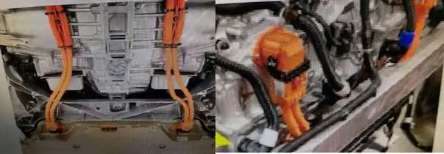
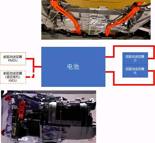
In the entire design, Tesla adopts an integrated approach to the rear drive system, which completely integrates the two sets of drive systems into one large unit, as shown in the following picture. There are high voltage connectors on both the left and right sides of the battery. In the three-motor version, the wires pulled out from the left and right sides need to be wound halfway around the rear drive assembly and then connected to the inverter on top.

In the control circuit diagram, Tesla has also configured two types of configurations for the front drive system. One is PMDU, which I understand to be a permanent magnet drive system, and the other is optional INDU, as shown in the following figure.

The design details of this drive system can only be deciphered after being completely dismantled. We need to wait for Rich Rebuilds or Monsieur Munro’s dismantling progress.
Control of Dual-Motor Rear Drive and Front Drive Systems
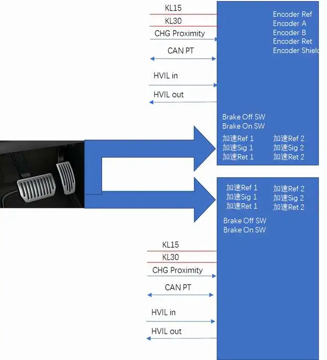
I carefully inspected the input signals for acceleration and deceleration, and within this three-drive system, the back two inverters are almost identical except for the signal from the encoder. Their inputs include power, charging proximity signal detection, HVIL circuit, and two sets of signals from the accelerator and brake which are respectively input into the two rear-drive inverters, and then communicated through one CAN PT.

The PMDU and INDU front-drive systems do not have separate front-drive settings, so they depend entirely on CAN PT for communication and control, with only power and HVIL circuit signals for input, which is especially simple. After looking at it several times, I found it a bit confusing.
In summary: this system has very powerful characteristics, but there seems to be a gap between our expectations and its control. Based on what we currently know about the Model S Plaid’s bus architecture, it is still based on several serial buses, including PT CAN, Chassis CAN, Body CAN, and Body FTCAN’s Private CAN. Ethernet is used for one link to the IVI and Autopilot controller, one link to the dashboard, and one link to the diagnostic data interface. Tesla’s engineers seem to pay less attention to this aspect.
This article is a translation by ChatGPT of a Chinese report from 42HOW. If you have any questions about it, please email bd@42how.com.