There were some incorrect personal judgments in my previous article on blade batteries for CMUs, and I must admit my mistakes. This situation made me realize that when evaluating technology, especially when evaluating the designs of others, restraint is important. Unless you have put in a lot of cost and effort to research, errors are easy to make in certain technical determinations.
Of course, I still wish to continue with my personal judgments and discussions of these technologies. Through these discussions, I can improve my own capabilities, and I am open to constructive criticism.
In this article, I will correct some of the information from my previous article and make some judgments about BYD’s CMU design direction.
Two Generations of CMUs
First, regarding corrections to the Chinese CMU information, the main points provided in the comment section were:
- There is balance, which is an internal balancing solution.
- There is cell temperature detection, and the NTC is attached to the battery cell and implemented through a reused communication connector, not on the PCB’s backside.
We will do a retrospective and comparison of this board:
Early design: Without using a daisy chain solution, an external balancing scheme was used, as shown below. We won’t go into too much detail here. The NTC collection is in the module, which is unrelated to the CMU design, and is a part of the module design.
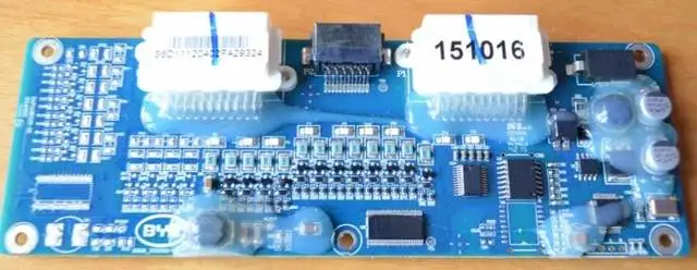
Mid-term design: This is the design for PHEVs, which use external passive balancing. Note that this battery cell has a capacity of 33, 37, and 40Ah, and NTC is also in FPC mode, as we saw before, as a result of using a sampling harness connector.
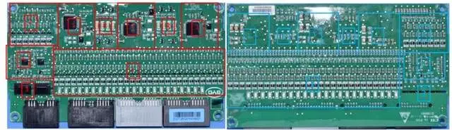
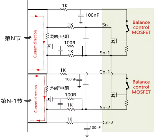
2020 design: Looking at the entire board, there are only four triodes, and the resistance is mainly at the bottom of the sampling connection, where there are a total of 14. I did not notice this. This design uses an external balancing resistor combined with an internal triode balancing mode.
Our typical design is to use the CMU’s power connection to directly measure the temperature of the battery cells from the board. If what is said in the comment section is true (which I believe it is), an NTC is attached to this 6-pin connector. Count carefully: the left side has four pins, and the right side has six pins. Eleven cells are collected by a single NTC. From the physical connection point of view, there is only such a possibility, because the backplate below is light and only has test points, and the CMU and module connections are all power connections.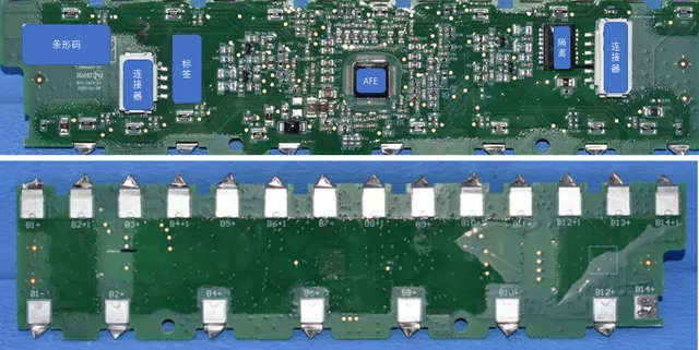
In the process of iterating the electronic management system, the capacity of the battery cells has increased while the ability of equalizing current has decreased. This is an apples to apples comparison issue, and it would be incorrect to deny it. However, the control object is not only the conversion from the standard module to the CTP’s sticky mode, but it may also contribute to the decrease in equalizing ability. If tested under the same conditions, more accurate conclusions can be drawn. Nevertheless, such testing is quite complex, requiring the purchase of actual boards, as well as the decryption of the board’s chain protocol and experimentation carried out within environmental boxes.
Note: Actually, our blog has no funding. The author is writing purely out of personal interest.
The focus of technical discussion
Pointing out the defects of others may involve certain risks. If someone criticizes my design, I will also feel uncomfortable and may argue back. However, my primary intention is to explore how CMU can perform in CTP through technical discussion.
As for the CMU design issues of this blade battery, we can view it from several dimensions. It is not necessarily about being right or wrong, but rather about choices.
Maintainability: Since the CMU is hard-connected to the module, if it fails, the entire battery must be opened up, and the CMU has to be replaced. Thus, maintainability may not be given much thought. Furthermore, if the lifespan of a component on the CMU is limited, it may lower the entire battery’s lifespan.
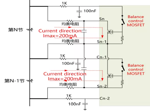
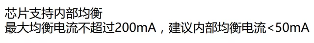
Equalizing current: Equalizing current is designed in three different levels: 200mA, 100mA, and 50mA. According to a friend’s explanation, the highest recommended design for a single channel of the blade battery is 100mA (nominal value in normal temperature), and equalizing the battery pack with the same group may require a decrease in current. Based on the evolution direction of the spec in the future, a design for 50mA may be considered.
Note: The currently used AFE and this principle are consistent. The specific specification and support capacity are different for different chips, but a considerable portion of chips may have similar capabilities in the long run.
 Accuracy and quantity of temperature sampling: As mentioned above, there is one sensor for every 11 battery cells which is directly attached to the cells through connector reusing. I will look for images to carefully review this specific approach later. The problem here is how to make this connection reliable. The approach used is to embed SMD NTCs into the copper/aluminum busbars by surface mounting, which causes temperature difference between the cell and copper/aluminum busbar.
Cost: As previously analyzed, considering the length factor of around 2000mm*70mm PCB, the stress on the resistor at the edge needs to be taken into consideration.
Of course, the analysis of these technologies is not actually that important, as the practical benefits and losses are evaluated by each company individually, and have nothing to do with others.
What is important in the long term is that BYD is importing its own MCU series, which includes BF7006AMXX, and AFE is also gradually using its own BF8915-1 (16-channel acquisition chip). This was also mentioned in the message. In the short term, Han EV is still using foreign chips, but in the long term, the blade battery system will gradually incorporate this design. I think we should pay attention to BYD’s attempts in automotive electronic chips, and that C company is investing in BMS and CMU chips intensively, which may lead to domestication of battery management systems in the future. The significance of keeping track of this is greater.
Conclusion: In the future, I will try to bring up disputable parts for discussion, in order to avoid any possible wrong conclusions caused by my mistakes (wrong understanding). If I make mistakes, it can also provide a more informative environment for further discussion for everyone. For reference only.
This article is a translation by ChatGPT of a Chinese report from 42HOW. If you have any questions about it, please email bd@42how.com.