In the process of game-changing between battery swapping and charging, there is an important factor that needs to be balanced in terms of energy storage solutions proposed by car companies for both approaches. The former involves having many fully charged battery packs ready for customers to swap, which can also be used as leverage for adjustment. The latter requires configuring a certain amount of energy storage in the regional system to mitigate the power demand brought by the ultra-fast charging. Tesla’s Powerpack is used for both large-scale energy networks and Supercharging networks to achieve balance.
It is worth noting that the latest generation of Powerpacks has utilized an integrated design technique similar to CTC.
Transformation of Two Approaches
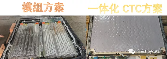
The design on the left shows the built-in module of the Powerpack. It actually uses two sets of Model S module in parallel, with cooling pipes running on both sides of the battery system. The electronic components, including the inverter and BMS, are arranged in the front compartment.
The design on the right is the new one, which eliminates the water cooling system by directly placing the battery packs together and adhering them as a whole. Based on the tag, this system uses a 900V system and a large number of battery cells are encapsulated with thick glue.

The specifications of 8.6 kW, 900V, and 88P shown here seem to be slightly off, as such a high voltage (250S) would require more than 88 parallel-connected battery cells, amounting to over 20,000 cells.
![Image 3 Specifications for Powerpack module]# Tesla’s Battery System
In this design, we can see the shape of the battery cells at the edge, which are thickly glued together for fixation.
From the cylindrical shape, compared to Model S and Model 3, this one doesn’t consider repair at all. If a single cell goes bad, it will automatically melt the fuse.
For this design, water cooling is currently not considered, so the design of the small energy storage battery relies entirely on the overall thermal equilibrium design.
At one end of the battery system tray, a weak pressure relief system is adopted; the overall structure is made of sheet metal material.

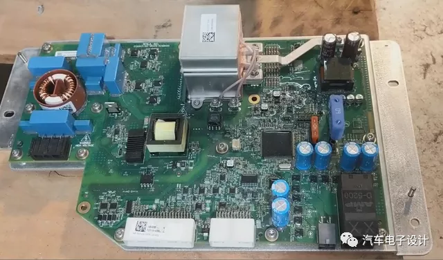
In the entire system layout, a special plastic wall is used to separate the battery part from the electronic and electrical part to avoid problems when injecting glue. From the layout, BMS is on the left, and a DCDC removed is on the right.


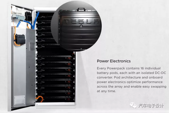
Since there are 16 small Pods built into the Powerpack, these DCDCs can be isolated and connected to the bus.

We can see interesting things happening in Tesla’s current iterations:
For automotive applications and energy storage systems, we see both parts being reused and in competition with each other. Leading technologies are being tested on both cars and energy storage systems.
The transition from the heat pump on Model Y to Model 3 doesn’t seem to follow the generational concept, but is changed after some experimentation.“`
The demand for fast-charging speed in the automotive industry can be converted into fast-charging power. The peak power of 250kW for a short period of time actually brings limited reduction in charging time, but significantly increases the design electrical network capacity load of charging facilities. Therefore, on the one hand, Powerpack is used to balance the demand for electrical network load, and on the other hand, it is also to prepare for further improvement of charging speed, preparing for the next step of 350 kW.
Summary: In fact, for this energy storage system, I have a small speculation. Currently, Tesla already has the technology reserve of 900V power electronics. Switching from 400V to 800V and then making another increase in the future is also expected.“`
This article is a translation by ChatGPT of a Chinese report from 42HOW. If you have any questions about it, please email bd@42how.com.
