*Author: Xiao Meng
Welcome to pay attention to the series of articles “Software Architecture and Implementation of Intelligent Driving Domain Controller”. Following the previous article introducing the basics and issues of software architecture, this article will present an overview of the software architecture of the intelligent driving domain controller, and elaborate on the composition of the software architecture from three dimensions.
Software Architecture and Product Architecture Supporting L3+
Automatic driving functions of Level 2 and below are basically belongs to the “driving assistance” nature. The main driving behavior of each function is dominated by the driver. The automatic driving system only operates the vehicle under very limited conditions. Moreover, the scenes formed by these constraints are basically independent, which is one of the reasons why each function can be independently developed by different suppliers.
Starting from Level 3, there has been a fundamental change in dominating the vehicle’s driving compared to Level 2.
Level 3 requires that in a good road environment, most of the operations will be dominated by the car. The vehicle will automatically perform a series of operations such as adaptive cruise control, lane keeping, automatic lane change, and automatic entry and exit of high-speed ramps. The driver only needs to intervene when necessary. This imposes higher requirements on the hardware computing power, sensor configuration, various perception, planning, and control algorithms of the automatic driving system.
In automatic driving technology, how to improve hardware computing power, especially the algorithm capability that supports deep learning, how to develop better perception algorithms, etc., are more concerned. However, it is rarely mentioned how to make these greatly improved specialized capabilities work together effectively.
What we need is not only that the technical modules related to various automatic driving functions can work together during the vehicle operation process, but also how to effectively decompose these different technical modules during the development stage. Because different technical modules are often completely different technical fields, they require different professional teams (or suppliers) to complete.
If these technical modules can be “disassembled” and “installed”, it is the problem that software architecture needs to solve.
Because the difficulty from Level 2 to Level 3 is too great, people have repaired the software and hardware architecture of Level 2 with the basis of increasing some new functions without changing the core architecture logic, which is called Level 2.5. However, the ability to repair on the original Level 2 architecture has limits. There must be a new architecture to support Level 3 and above automatic driving.
Bottlenecks of Level 2 Software Architecture
The previous article mentioned the solution of “multiple independent automatic driving controllers + domain controllers”. It is mostly used for the development of Level 2 and Level 2.5. The bottleneck of its software architecture is at least as follows:1. Multiple independent controllers result in inefficient coordination of computing resources, leading to both wasted and insufficient computing power. For example, the fully automated parking assist function and ACC/AEB function are not enabled simultaneously. After the speed exceeds 20 kilometers, the parking assist function stops executing while the ACC/AEB can be enabled. However, the computing power of the parking assist system cannot be used for the ACC/AEB function. The situation is reversed at low speeds.
-
Communication delay within the domain of intelligent driving. Communication between multiple controllers can only be done through the bus, which causes some data delay. If a high-speed Can bus (1 Mbps) is used, for example, one millimeter-wave radar can transmit 30 targets per cycle, which can reach 50% of the bus load.
-
The autonomous driving functions of each controller lack a consistent architectural design and can only communicate data through signals and coordinate through domain controllers. As more functions are stacked, complexity becomes difficult to maintain.
-
The design based on functions (ACC, LKA, TJP, etc.) is difficult to cope with scene-based scheduling required by Level 3 or above. The more functions are implemented, the more difficult it is to define the boundaries of the functions, and without a consistent architectural design, parallel functions will cause exponential complexity.
-
The independent controllers cannot effectively share common components, resulting in duplication of work.
-
The implementation of the functions of each controller cannot utilize the perception results calculated by other controllers, resulting in a waste of resources.
It is under these circumstances that the domain controller for intelligent driving is becoming more centralized, which means that these controllers are concentrated in a high-performance domain controller.
Even if there are other controllers within the domain, they are mostly low-intelligence, generally only doing some single-item perception and obtaining raw data. However, the perception algorithm is still completed within the domain controller. After being highly centralized, a new software architecture is required for the high-performance domain controller.
Software Architecture Bird’s Eye View
The domain controller for intelligent driving is a very complex system, and its software architecture involves many aspects. It is difficult to understand the overall structure accurately from a single dimension. The following figure describes the overall software architecture from three orthogonal dimensions from a bird’s eye view at an altitude of 3,000 meters.
“Orthogonal” is a mathematical concept that means the vertical generalization. Here, it means that the two dimensions of classification are independent and unrelated.
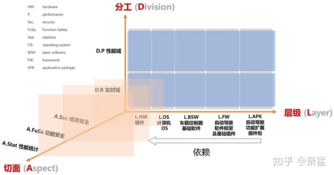
2.1 First, let’s talk about the “Hierarchy” dimension
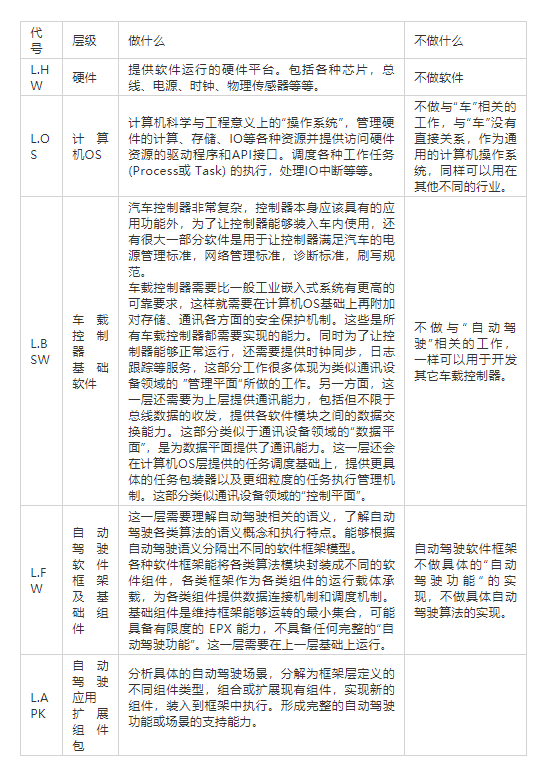
From left to right, the hierarchy gradually increases, and each layer depends on the layer to its left to complete the work. Although this article is about software architecture, I also include hardware in the figure for convenience, as software depends on hardware. We understand the role of each layer from two perspectives:
-
What does this layer do?
-
What does this layer not do?
2.2 Division of Labor between “Real-time Domain” and “Performance Domain”
In intelligent driving, the higher the requirement for real-time planning and control at the end, the higher the demand. Hard real-time requirements need to respond and complete within a certain predetermined time. This requires the hardware and computer OS to provide basic guarantees together. Generally, a relatively simple real-time system is implemented by running on an MCU. The computing power of the MCU is limited, and its computing resources are several orders of magnitude worse than the demand for vision algorithms based on machine learning.
Therefore, SoCs that integrate high-performance CPUs and AI computing resources are needed to meet the requirements of high-performance computing. This divides into the “real-time domain” and the “performance domain”.
In the performance domain, the operating computer OS generally does not meet hard real-time requirements but tries to meet soft real-time requirements. For example, Linux has a kernel patch that supports real-time capabilities. However, it is not enough just to apply a patch for real-time requirements. It is also necessary for application programs based on Linux to utilize the capabilities provided by the real-time patch.
In the three-dimensional diagram above, “Division of Labor” and “Hierarchy” are orthogonal axes. That is to say, each segment on the “Hierarchy” axis has a corresponding object in both the “real-time domain” and the “performance domain”. Each target often corresponds to a specific software product. The table below lists some combined examples:
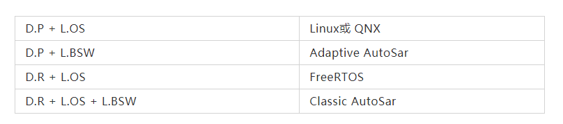
AutoSar Classic is quite special as it belongs to the real-time domain but spans two layers on the hierarchy axis.
3.2.3 Aspect
Aspect is a concept in software architecture. In the programming paradigm, there is a concept called “aspect-oriented programming” (AOP). The basic meaning is to divide the software functions into “core business” and “peripheral business” in software architecture:
The core business refers to the functional system that completes the actual business logic, such as algorithm execution, scene switching, etc.
Peripheral business refers to those functions that will not affect the execution of the core business even if they are not implemented. For example, performance statistics, information security, etc. It does not mean that these functions are not important but that after distinguishing it from the core business logic, it is easier to understand and implement the core business. At the same time, similar aspects of peripheral business can be planned and implemented with a more global perspective, which can design appropriate proprietary architecture for the corresponding aspects and then integrate them with the core business.In the three-dimensional graph above, each intersection point in the plane formed by the D and L axes represents a product, and this intersection mapping on the A axis represents the function that needs to be achieved by the corresponding section of the product.
For example, D.R + L.HW represents the hardware MCU, which needs to achieve ASIL-D level in the A.FuSa plane. Because the software technologies involved in each intersection point of the D and L axes differ greatly, the technological solutions adopted for each demand point projected onto each plane on the A axis are also very different.
Therefore, during system development (the system development stage in the upper left corner of the V-model), overall design requirements can be proposed for a certain section. However, when implemented at each DL axis intersection point, it should be implemented separately by the product development team corresponding to that intersection point. It is impossible for one team to implement all functions of a complete section.
ROS/ROS2 and “Middleware”
As ROS/ROS2 is often used for prototyping autonomous driving systems, we discuss the position of ROS/ROS2 in the above three-dimensional graph and whether it can be used for mass production of intelligent driving.
First of all, let’s clarify the concept of OS. ROS is a robot operating system. Although there are letters of OS in its name, this OS is not the same as the general meaning of OS, which usually refers to computer operating systems such as Windows, Linux, MacOS, RTOS, and so on.
To avoid ambiguity, in this article, we use the full name “computer OS” or “computer operating system” instead of abbreviations.
In a broad sense, an OS provides a set of software solutions and application interfaces for a specific professional field, and users in that field can simplify relevant development based on this interface. Therefore, this software system solution can be called a domain-specific OS. ROS is a domain-specific OS for solving robot software development.
However, in reality, the applications written using ROS or ROS2 only run as processes on top of a computer OS, but linked with the libraries provided by ROS/ROS2. ROS/ROS2 also provides convenient software packages for robot development, such as some algorithm or coordinate conversion tool libraries.
Because an autonomous driving car is, in a sense, also an autonomous driving robot, ROS/ROS2 can be used for prototyping autonomous driving, and the ROS/ROS2 ecosystem has many convenient tools that can provide a lot of convenience for development.
In the three-dimensional graph above, the position of ROS/ROS2 is in the intersection area of (D.P + L.BSW) and has some extension towards the (D.P + L.FW) area. However, it only covers a small part of these two areas. Moreover, there are almost no features implemented on the A axis.3.1 The role of ROS / ROS2 in (D.P + L.BSW)
The table above provides a detailed description of the tasks that need to be performed in the L.BSW (vehicle control software) layer. Corresponding closely with the concept of communication network devices, a large part of this layer involves management tasks, while also providing communication capabilities.
Generally, specifications for the framework for developing applications based on L.BSW functionality will also be proposed. ROS / ROS2 mainly provide communication support capabilities in the L.BSW layer, enabling decoupling of various application nodes through the publish/subscribe mode. The basic management capabilities required by the vehicle controller are poorly implemented in ROS / ROS2.
Some people believe that ROS2 cannot be used for industrial vehicle controllers in mass production because its communication real-time performance is insufficient. However, this is a misunderstanding. ROS2 was not originally designed for real-time domains. If it is necessary to run vehicle control algorithms with high real-time requirements in ROS2, it is a design error (prototyping system is irrelevant, it’s not feasible for mass production), rather than a problem with ROS2. Can ROS2 be used for mass-produced intelligent driving controllers?
The answer is yes, provided that all the functions required by the L.BSW layer and all the characteristics required by all aspects of the A axis are completed. In fact, this can be achieved by implementing an AP AutoSar specification based on the ROS2 architecture. This can be a stand-alone product that can be developed with sufficient investment in time, manpower, and money. It’s just a matter of whether it’s necessary and whether it’s worthwhile.
3.2 The role of ROS / ROS2 in (D.P + L.FW)
Indeed, ROS / ROS2 have implemented an application framework for robot development and have provided many basic components, which greatly facilitate the development of robot applications. However, the current robot applications are mostly moving in a very small area. The range of warehouse robots is generally several hundred meters at most, and the scene is relatively simple.
Therefore, the support provided by ROS / ROS2 for robot development is mapped to intelligent driving, and is mostly reflected in the innermost layer of the fractal and recursive EPX model. That is, the perception, planning, and control execution of a single scene at short distances. It does not provide a scheduling mechanism (S) for complex scenes or an arbitration mechanism (A) for execution in parallel with multiple scenes. After all, there’s no need for a robot to walk from Beijing to Guangzhou.
Therefore, as a software development framework for intelligent driving, ROS / ROS2 still has many shortcomings, but it is still a good choice as a rapid prototyping tool.
3.3 About “middleware”As the name suggests, “middleware” must be in the middle of two layers to shield the underlying complexity from the upper layer. There is a saying in computer software architecture: “Any problem in the field of computer science can be solved by adding an indirect intermediate layer.” This is a major design philosophy in software architecture design, which has been used in countless places and solved countless problems. Moreover, the term “middle” is also relative. When there are multiple layers stacked, each layer is the middleware of its upper and lower layers.
Therefore, when we say “middleware,” we need to specify its context, otherwise there may be inconsistency in expression and understanding.
When we say that AP AutoSar or CP AutoSar is middleware, this middleware has a clear L.BSW-layer semantics. That is, it is located between the computer OS and the specific ECU function implementation, shielding the details related to specific processors and computer OS from the ECU function implementation layer, and realizing the basic services required for interaction with vehicle networks, power systems, and other systems.
When we refer to “ROS/ROS2 as middleware,” its meaning is not equivalent to “AP AutoSar as middleware.” ROS/ROS2 is an application framework for robot development, providing a general middleware framework and commonly used software modules (ROS Packages) between robot applications and computer OS. Moreover, the ROS team believes that this framework is well done and can be called an operating system (OS).
The L.FW layer is between the L.BSW and L.APK layers, providing software frameworks and basic components for the development of autonomous driving functions or scenarios. It is also middleware for its upper layers. If it is well done, it can also be called an OS, which is the “autonomous driving OS.” Anyway, everything is relative.
To avoid ambiguity, this article generally does not use the term “middleware.” If it is used, it will also clearly indicate which two layers it represents. In most cases, we use “Vehicle Controller Basic Software” to represent the basic software functionality that any automotive electronic ECU needs to implement. It is the middleware layer between the computer OS system and the actual ECU function layer (FW + APK). Codenamed L.BSW.
The second article of the content will be shared here, the next article will be shared: “Autonomous driving software framework and basic components supporting Level 3 or above functions.” Stay tuned!
This article is a translation by ChatGPT of a Chinese report from 42HOW. If you have any questions about it, please email bd@42how.com.