Author | Aimee. Peng Xiangxu
In the design process of autonomous driving system, GNSS/GPS is required for high-precision map positioning of vehicle location. However, GNSS/GPS has the following differences or limitations for autonomous driving positioning accuracy:
1) GNSS/GPS requires continuous external satellite information to be able to locate. Generally, the positioning accuracy of GPS is insufficient between 1-3 meters, and the positioning information is prone to interruption or weakening due to the obstruction of buildings, elevated roads, tunnels, and leaves.
2) The positioning frequency of GNSS/GPS is relatively low, and the measurement sampling frequency is strongly limited by the sensor output frequency. Therefore, the GPS positioning accuracy is far from meeting the needs of autonomous driving.
Generally, positioning errors are particularly serious in the following scenarios for autonomous driving detection performance:

a) Poor lane changing of the vehicle
The automatic lane changing process of HWP requires the vehicle to have a high positioning accuracy for the self-lane and adjacent lanes. The error in vehicle positioning may cause the vehicle to enter a prohibited lane change lane or cause overshooting into the third lane.
b) Collisions caused by congestion following
When there is traffic congestion on the road, positioning errors may cause the distance between front and rear vehicles to be too close. When referring to the current following control algorithm, this may cause collisions such as rear-end collisions and scratches between vehicles.
c) Failure to stop in time
When the autonomous driving function fails, the system may plan the vehicle’s trajectory to the emergency lane or perform safe parking on the same lane. If there is a large positioning error, it may stop directly in the opposite direction on the overtaking lane.
d) Incorrect ODD transmission
When the vehicle’s real-time positioning is inaccurate, the deviation between the high-precision map’s ODD and EHP information will affect vehicle control decisions and endanger vehicle safety.
As mentioned above, if only traditional high-precision positioning methods are used, we cannot completely trust their detection results. Thus, another method is needed to accurately determine the vehicle’s position on the map.
The most commonly used approach is to compare the output content of the vehicle sensor terminal with the content displayed by the original map signal. The most commonly used positioning measurement method in autonomous driving is to measure the distance between the vehicle sensor and the static obstacles on the road edge (such as trees, power poles, road signs, or buildings). The process involves comparing the sensor’s measurement values with the map’s measured road-edge static target data to determine the actual vehicle position location information from the matching result. To perform this comparison, it is necessary to be able to convert data between the sensor’s own coordinate system and the map’s coordinate system. At the same time, the vehicle’s precise position must be determined on the map with an accuracy of ten centimeters.Here we can improve positioning accuracy by using Real Time Kinematic (RTK) system, which provides real-time dynamic positioning based on carrier phase observations, and can achieve centimeter-level accuracy. In RTK mode, the base station can transmit observation values and coordinate information to the rover station through the data link. The rover station receives observation data from both the base station and GPS, and generates differential observations for real-time processing. RTK’s contribution to measurement accuracy mainly lies in the need to establish several base stations on the ground, and the accurate position of each base station is known. After receiving GPS measurement position information, each base station compares it with its own known ground position information deviation, and uses the comparison error as the correction baseline to correct the position positioning results of other GPS receivers.
With the assistance of RTK system, the error caused by pure GPS positioning can be greatly reduced. However, the obstruction and update frequency issues still exist.
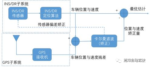
Design principle block diagram of combination of inertial navigation system (INS) and GNSS
To further improve positioning accuracy, a more advanced and practical method is to use a combination of GNSS and INS, which is known as the inertial navigation system. As we know that using a simple inertial navigation system to complete positioning will cause accumulation of errors over time, and the errors will become larger and larger. When the GPS receiver obtains enough measured values, it can ensure the corresponding accuracy.
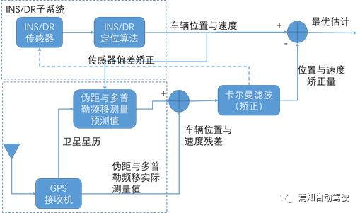
In most cases, the combination of inertial navigation system and GNSS positioning system is mainly divided into the following categories: loose combination and tight combination, with corresponding structures as shown in the figure below.

In the loose combination as shown in the above figure, GPS and INS need to perform their own calculations for vehicle speed and position, and the difference between the calculated values is used to generate sensor bias correction values after Kalman filtering. The correction value is then input to the inertial navigation sensor, and the vehicle position and velocity are updated through the INS positioning DR algorithm, and the optimal estimated value is finally obtained by subtracting the previous Kalman filter output correction value.
 In the tightly coupled and loosely coupled integration of inertial navigation system (INS) and Global Positioning System (GPS), the GPS receiver corrects its bias by taking the difference between the measured and predicted pseudorange and Doppler frequency shift values and then inputting them into a Kalman filter. The corrected values are then referenced to the algorithm structure of the previous loosely coupled integration to ultimately achieve optimal estimation.
Regardless of whether it is tightly or loosely coupled integration, the feedback adjustment of the output to the input is reflected only in the real-time adjustment of the detection error of one end (GPS) to the other end (INS), and whether GPS itself has detection error or cumulative error is not corrected in real time. Therefore, a hybrid error correction scheme that considers the bias correction of both INS and GPS for the impact on the input by sensors is a typical and commonly used method, combining the above two integration defects. The data of INS corrected for bias is input into the GPS measurement prediction module, and then both the generated GPS correction data through a Kalman filter and the INS-corrected data simultaneously act on the GPS receiver, and the input result can perform real-time error correction for GPS. This process leads to a more accurate optimal estimation result compared to performing only one type of error correction.
The Design of Location Combination in Autonomous Driving
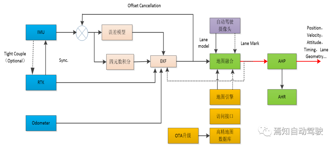
Location combination in autonomous driving system design is often not a single process. In general, it is advantageous combination of various types of location sources to achieve optimal location. In recent years, multi-sensor fusion solutions, such as GPS+IMU, have become increasingly important because the passive location source, IMU, can complement the shortcomings of GPS. In addition, vehicles can also carry odometers and visual devices to form more diverse multi-sensor fusion solutions. The detailed location architecture analysis diagram below shows that common location sources include traditional GPS high-precision positioning, wheel speed sensors, RTK, IMU, and camera data transmission method as the leading sensor.

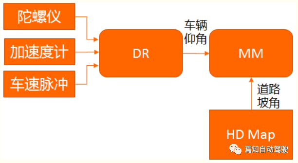
Based on the above analysis, to ensure good location accuracy and robustness in autonomous driving, it is required that the location model has a comprehensive fusion location algorithm, a high-performance IMU, and if conditions permit, dual-frequency RTK should be used to enhance GPS location. Here, we will focus on the location algorithm and conditions related to IMU.The most important part of IMU is its DR (Dead Reckoning) navigation algorithm. The DR algorithm refers to the process of using sensor observation values to calculate the navigation state at the next moment based on the known navigation state (state, velocity, and position) at the previous moment. The DR algorithm includes two parts: attitude arrangement and position arrangement. The attitude arrangement uses the AHRS (Attitude and Heading Reference System) fusion algorithm to output the vehicle attitude information after processing.

The accuracy of DR navigation calculation is related to the performance of the DR algorithm, especially the calibration accuracy of the odometer system error and gyro zero bias. 50% of the positioning error comes from the zero drift, and 50% comes from the gyro scale error. Finally, the relationship between gyro zero bias changes and lateral errors caused by zero drift can be expressed in terms of speed. Therefore, according to the positioning error, the performance indicators for the IMU can be obtained. The maximum value of zero drift is 10 °/h.
In addition, since the accuracy of the DR algorithm mainly depends on the errors of IMU (gyroscope and accelerometer) and speedometer, gyroscopic errors will cause position errors to increase quadratically over time, and speedometer errors will cause position errors to increase linearly over time. In order to improve the positioning accuracy in the absence of GPS signals, device error compensation must be performed. The main function of the compensation module is to use GPS data to compensate for the error parameters of the velocity sensor (proportional factor) and the IMU (gyroscope vertical proportional factor and gyroscope three-axis zero bias). The purpose of compensation is to obtain reliable navigation information only by DR algorithm in the absence or weak GPS signals. Therefore, we need to fully consider the performance indicators of corresponding compensation parameters in the initial selection of IMU devices. Specifically, the performance indicators for IMU can be refined according to the following table.

Safety Conditions for Autonomous Driving Localization
In order to understand the safety conditions for autonomous driving localization, we need to first understand the road driving localization boundary. We know that vehicle localization is actually to accurately understand the real-world coordinates of the central point position in both horizontal and vertical directions. The roads we actually drive on are non-linear, so here we assume that the vehicle is traveling within a certain lane with a certain center point as the center and a certain radius during a certain period of time, while considering the error tolerances of the vehicle in the horizontal and vertical directions. A certain rectangular framework area is defined for the vehicle. At this time, the corresponding vehicle driving structure diagram is shown below.The geometric relationship for road driving based on the traveling model diagram shown above is illustrated as follows:

By transforming the relationship, we can derive the correlation between x and y:

Here, x and y represent the positioning error rectangle with double horizontal and vertical positioning error values, respectively, based on the actual position value of the current vehicle. As long as the two values are limited within a certain range in our setting of positioning error correction, the positioning accuracy can be ensured.
So how do we define the positioning accuracy requirement for autonomous driving? We can refer to the maximum deviation when the positioning fails, and the system can control the vehicle to stop safely without deviating from the lane as the critical condition for judgment. Assuming the current autonomous driving speed is 120 km/h, and the IMU carried by the vehicle can generate 300 m of trajectory calculation under the driving state when the RTK suddenly loses lock and the road lane line is not clear, the entire high-speed driving time is approximately 9 seconds. Therefore, we require the system to still have relatively accurate autonomous positioning capability during this period, that is, within FTTI (~50ms) to quickly and accurately judge RTK outliers, lane recognition errors, and other abnormal conditions. This process can help the system identify dangerous states and issue takeover requests, providing sufficient transition time to remind the driver to take over the vehicle, while the system controls the vehicle to stop safely.To ensure that the vehicle does not deviate from the lane during a safety handover request, it is required to maintain the lateral error calculated from a 300 m flight position in a certain threshold range. Generally, the positioning parameters required by the IMU are 1σ indexes, and the errors are normally distributed. The 3σ result can be considered as three times that of 1σ. Assuming that the car is driving on a horizontal road surface, the projection of the x and y axis angular velocities on the horizontal plane is temporarily ignored. That is, when the self-positioning error occurs and the maximum lateral deviation Dmax is used for middle driving, assuming that the adjacent lane vehicles also drive along the edge of the lane line, at this time, the actual lateral displacement on the left side of the self-car is Dmax+0.5 times the width of the car. Assuming the width of the car is 2 m, the actual lateral displacement is 1.8 m. Assuming that the road is a standard lane with a width of 3.75 m, half of the car width is about 1.85 m, and the self-car will have a high risk of collision with the side adjacent vehicles at this time. Considering the vehicle width and the lane width, in order to prevent the positioning error from causing a collision between the self-car and the adjacent lane vehicles, it is generally required that the 3σ positioning error for trajectory calculation through the IMU on the expressway cannot be greater than 0.8 m.
Based on the above analysis, when RTK loses lock, GPS positioning will not be available. When the camera detects that the lane line is unavailable, the system can only calculate the trajectory through the IMU. At this time, in order to ensure that the vehicle has sufficient reaction time to take over, it is required that the entire stage still has a lateral positioning error tolerance of 0.8 m and a longitudinal positioning error tolerance of 3 m within the 300 m travel, referring to the 3σ standard, the confidence of the entire process can still reach 99.7%.
Summary
The positioning problem of the vehicle has always been an issue for autonomous driving on city roads, tunnels or highway canyons. The reason is that these extreme environments make it impossible for the vehicle to receive GPS signals or related sensor signals are interfered with, resulting in no GPS positioning results or poor positioning accuracy. This is an inherent drawback of “active positioning,” which cannot be overcome algorithmically. To address this issue, the GPS+IMU multi-sensor fusion solution is receiving increasing attention because the “passive positioning” IMU can fill the gap of GPS. In addition, the vehicle can also carry odometers, more sensor devices to form a richer multi-sensor fusion solution.For basic positioning, map data is the soul of positioning business. Multi-sensor fusion is only a part of the positioning business. To achieve high-performance positioning fusion effect, it is important to combine multi-sensors with map data using GPS, IMU, odometer and other sensors along with the advantages of basic maps. This is also the** mainstream direction **that future autonomous driving pursues.
This article is a translation by ChatGPT of a Chinese report from 42HOW. If you have any questions about it, please email bd@42how.com.