Author: Zhu Yulong
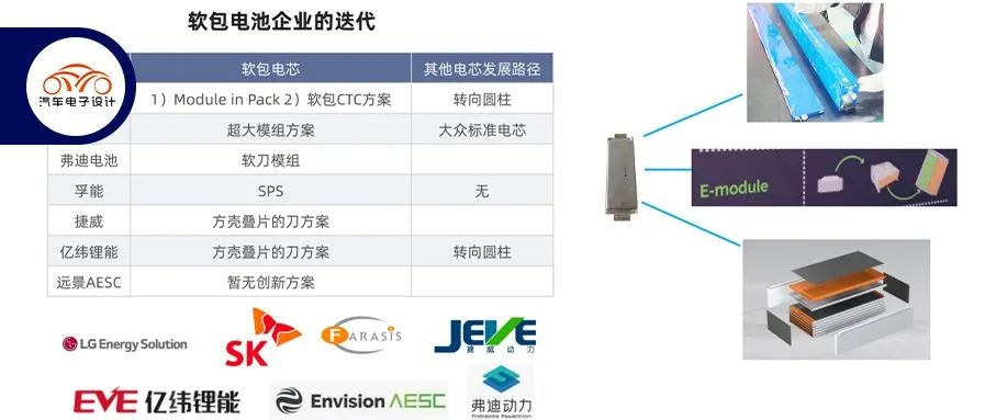
On the iteration of soft pack batteries, the impact of the two recalls by LG Energy in the past was particularly significant, especially in the face of the global import requirements for EVS-GTR, which require a 5-minute warning. For the thermal runaway of batteries, both cylindrical and prismatic cells are designed towards the goal of No Propagation (NP). Therefore, we see that the current global solutions mainly fall into several categories:
-
Soft Knife: This is actually similar to BYD’s design, with multiple cells connected in series and mounted into a shell. There are also variations of this design that involve using a non-metallic shell bracket to achieve grouped designs.
-
Short Knife and Long Knife: After wrapping the cells with insulation film, they are loaded into prismatic cells and designed according to the method of dual-end output.
-
Large module or Module In Pack concept: Integrating a water cooling plate into the module and making 2-4 large modules, which can also achieve a relatively high grouping rate.
-
SPS: Let’s take a closer look at the design released by Funeng this time.
In my opinion, for the next step in global battery designs, short knife and long knife designs will become the mainstream, and we will take a closer look at whether Funeng’s SPS solution is feasible.

Grouping Solution
This new power battery solution is called SPS (Super Pouch Solution), consisting of large soft pack cells, large soft pack battery systems, and large soft pack battery manufacturing. I haven’t seen any characteristics of grouping in terms of recycling.

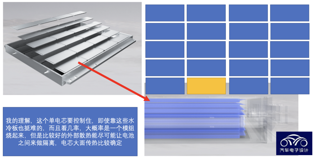
The design principle is similar to SAIC’s “Magic Cube Battery.” Due to the relatively thin profile of the large soft pack cells, the SPS design by Funeng Technology is easier to arrange horizontally. According to Funeng’s statement, it can reduce battery system components by 50%, reduce material costs by 33%, and increase volume utilization to 75%.
 This design is to provide a shell for soft-pack battery cells and stack them together. The efficient combination of liquid cooling plates and thermal conductive sheets provides efficient heat exchange of “dual-side liquid cooling and triple-side heat transfer” for large-scale soft-pack battery cells, improving the heat dissipation efficiency of the battery system by four times. The main difference between this and the previous AESC design is that the large soft-pack battery cells form six-sided protection and are equipped with a design of efficient exhaust channels and heat exchange capabilities. The SPS large soft-pack battery system is equipped with 8-series or higher nickel content cells, and the thermal runaway of a single cell does not spread (NO TP), which means that if one cell fails and catches fire, the stacked module will not catch fire as well, similar to the magic cube battery.


Compatibility of Cells and Modules
Here, the main design change of the cell is through the tab of the full-pole ear and multi-pole ear large soft-pack power cell. Therefore, some special processing can be done by reducing the link impedance on the Tab output. The design direction of the cell includes:
-
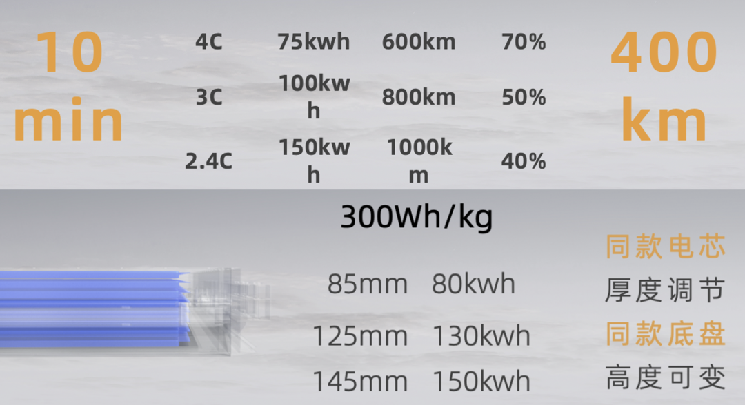
One is to have a charge and discharge rate of 2.4C to 5C or even higher (2.4C, 3C, and 4C fast charge cells, corresponding to charged amount of 150kWh, 100kWh, and 75kWh, respectively).
-
The other is to use a semi-solid-state electrolyte to reduce the amount of liquid electrolyte, improve the intrinsic safety of the cell, and create high-energy-density cells.
Therefore, this approach is highly compatible with the material system in the NP design, covering materials systems from high-nickel ternary to low-nickel-rich lithium manganese, lithium iron phosphate, sodium-ion, and other material systems.
The first-generation products of sodium-ion batteries, lithium iron phosphate, and lithium manganese iron phosphate are planned to be launched in 2023, with the goal of forming products with energy densities ranging from 200Wh/kg to 240Wh/kg by 2030.
Regarding low-nickel, a low-nickel-rich manganese system product with a specific energy of 250Wh/kg will be launched in 2024 and 290Wh/kg by 2030.
Note: It would be great if high-nickel can be done well here.“`

Of course, the semi-solid large pouch cells are directly integrated into the system chassis, and I don’t quite understand this approach, but my understanding is that they are stacked up one by one and the overall approach remains unchanged.
In any case, the advantage is to be able to replace the battery cells and adjust the stack height (adjust the thickness of the large pouch cells laid horizontally), to achieve compatibility with SUVs and sedans (85mm to 145mm). This has also been attempted on the Rubik’s Cube battery with a square shell design, but compatibility with different thicknesses means different battery cells, and stacking layers will be easier.

Summary: I think the stacking method that LG used for GM’s race car before is actually a bit similar to this one, but the disadvantage is that the energy density is not too high, and the insulating material may be less, mainly using cost-effective materials for insulating filling and through the external water cooling system to continue heat dissipation, which may be able to achieve NP.
“`
This article is a translation by ChatGPT of a Chinese report from 42HOW. If you have any questions about it, please email bd@42how.com.
