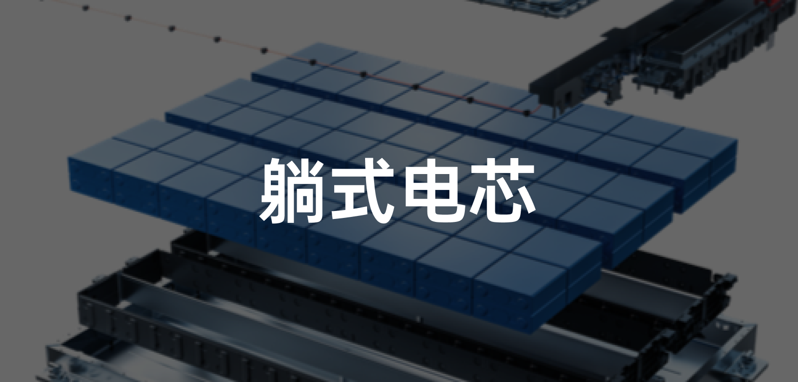
On August 10th, I had the opportunity to attend the live online course on battery technology analysis for the Roewe iMAX8 EV. At the MG MULAN debut press conference, Zhu Jun, the Vice Chief Engineer of SAIC Group and General Manager of JEN, who is also known as the “Father of SAIC New Energy”, gave a detailed explanation of the LBS lying battery technology and the ecosystem of the Mo-Fang battery. For more information, you can click on this link: “MG CEO Zhang Liang: MG MULAN benchmarks Model 2“.
The LBS lying battery cell technology is the core of the Mo-Fang battery, and a wide range of gradient coverage can be achieved by combining battery cells with different sizes and chemical formulas. This is because SAIC Group has many internal brands and the range of vehicle models in the subdivided market is also very large:
-
Capacity ranges from 44 kWh to 150 kWh, and the battery cell layout in the battery pack ranges from 96 to 108 series.
-
Electrochemical systems, compatible with low energy density iron phosphate lithium, medium energy density 5/6 series ternary, high energy density semi-solid-state batteries and even emerging but not yet mass-produced battery types such as sodium-ion batteries and phosphate batteries.
-
The width and length are fixed at 1,300 x 1,690 mm, and the thickness varies with three options: 110 mm, 125 mm, and 137 mm.
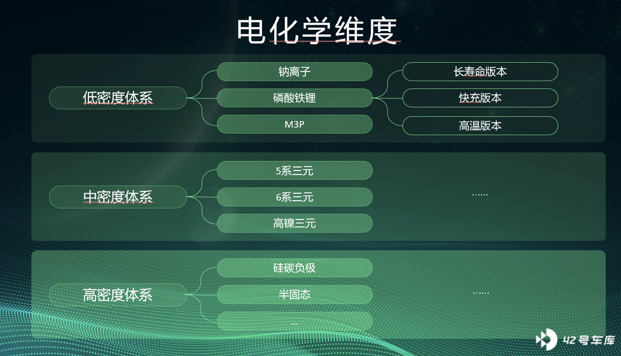
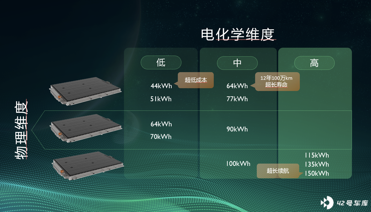
People cannot lay down, but battery cells can. Today we will take a look at the highlights of the SAIC “lying flat” Mo-Fang battery.
Energy density is the foundation
As electric vehicles have developed so far, one of the core indicators that people look at is the range, or in other words, the capacity of the battery pack. The problem is that the size of the vehicle is constant and the battery pack needs to increase its capacity on the basis of minimal volume change.
With this “tight spell”, automakers can only try to cram more batteries into the battery pack to increase the energy density of the battery pack.
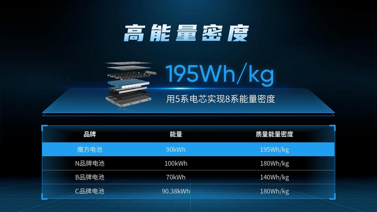 We generally use Wh/kg or Wh/L to measure the energy density of battery packs. The energy density of the magic cube battery pack can reach 195 Wh/kg, which is undoubtedly first-tier level, while the mainstream industry’s energy density is only around 180 Wh/kg. More importantly, SAIC achieved 195 Wh/kg of Pack energy density on the basis of a 5-series formula with lower cell energy density.
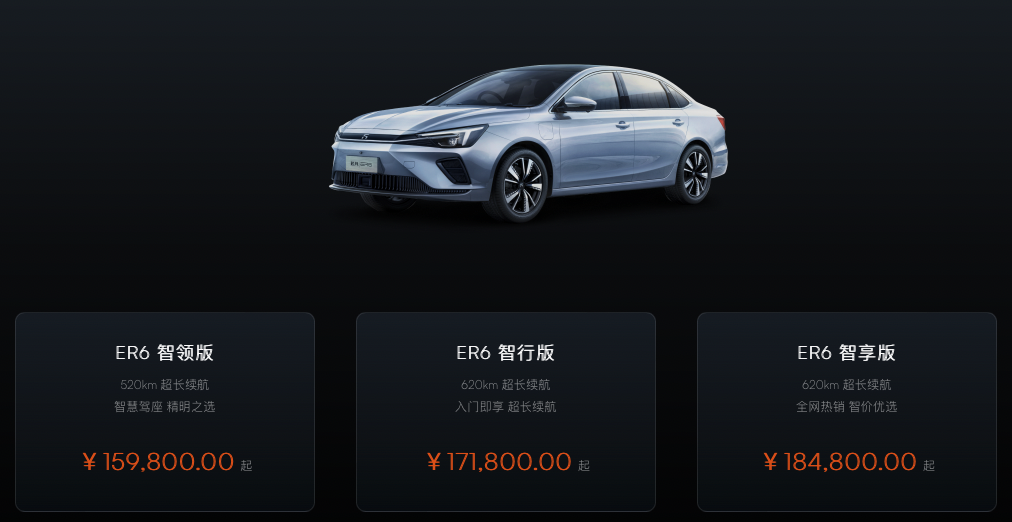
SAIC has a tradition of improving the energy density of 5-series batteries in battery packs. Several years ago, SAIC’s R brand’s ER6 achieved a range of 620 km in NEDC using a 72.7 kWh 5-series battery pack.
Looking at the parameters, the energy density of the entire battery pack reached 180 Wh/kg. This is a top-notch number among compact sedans, whether it comes to range or the energy density of the battery pack.
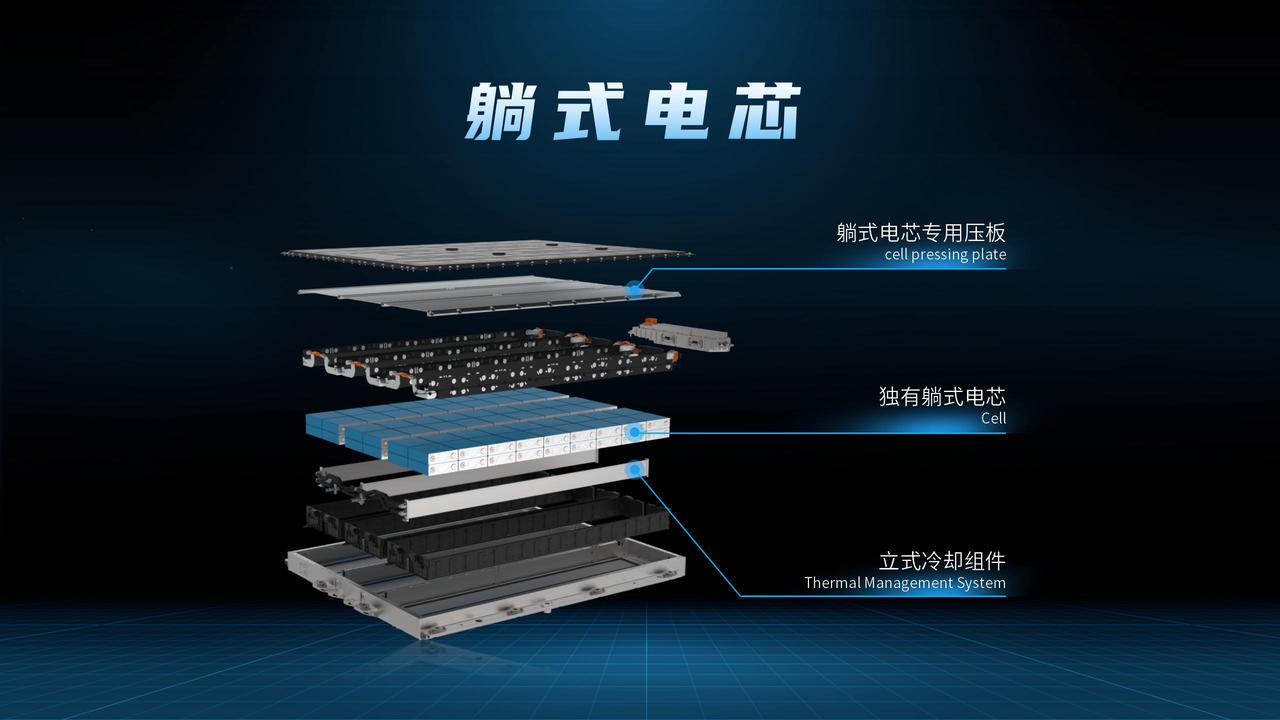
For the updated Magic Cube battery pack, there are not many options for SAIC to further improve its energy density.
As we know, there are mainly two ways to improve the energy density of battery packs: one is to reduce the physical modules through CTP, which can put more battery cells in the same size battery pack; the other is to increase the energy density of the battery cells to achieve an increase in overall density.
Both of these points are reflected in the Magic Cube battery pack.
In addition to using CTP technology to increase energy density, after the traditional cylindrical batteries lay down, the volume utilization rate of the lay-down batteries has also been improved to some extent.
In traditional cylindrical batteries, the thickness of the top cover, the distance from the top cover to the diaphragm, and even the thickness of the bottom support all affect the overall volume utilization rate, which makes the “yield” insufficient to the limit.
Laying down the batteries doesn’t require too much consideration of the problem above. Finally, the energy density of the 5-series battery pack was further increased to reach the 195 Wh/kg.
Only with competitive energy density can advantages be brought in terms of range parameters. Taking the protagonist ROEWE iMAX8 EV as an example. The 90 kWh Magic Cube battery it uses can support this MPV with a weight of 2,230 kg for a range of 570 km under the CLTC standard.
However, while stacking energy density, many problems were encountered, such as how to deal with thermal runaway and whether the life cycle can reach standards.## The Commonplace Issue of Thermal Runaway
The core issue of battery safety is to control and reduce “thermal runaway”.
Thermal runaway refers to the abnormal increase of temperature and pressure within a battery. When the rate of heat generation from the exothermic reaction is higher than the heat dissipation rate of the power battery, the internal pressure and temperature of the battery will rapidly rise, entering an uncontrollable self-heating state. If not controlled, this can lead to battery combustion.
The reasons for this phenomenon can be divided into two categories: short-circuiting and overcharging. They are induced by various specific factors, which I won’t go into detail here. You can refer to the picture below.

For OEMs, no matter which company produces the battery, they cannot escape from the “surrounding and intercepting” of the thermally runaway cells. SAIC is no exception.
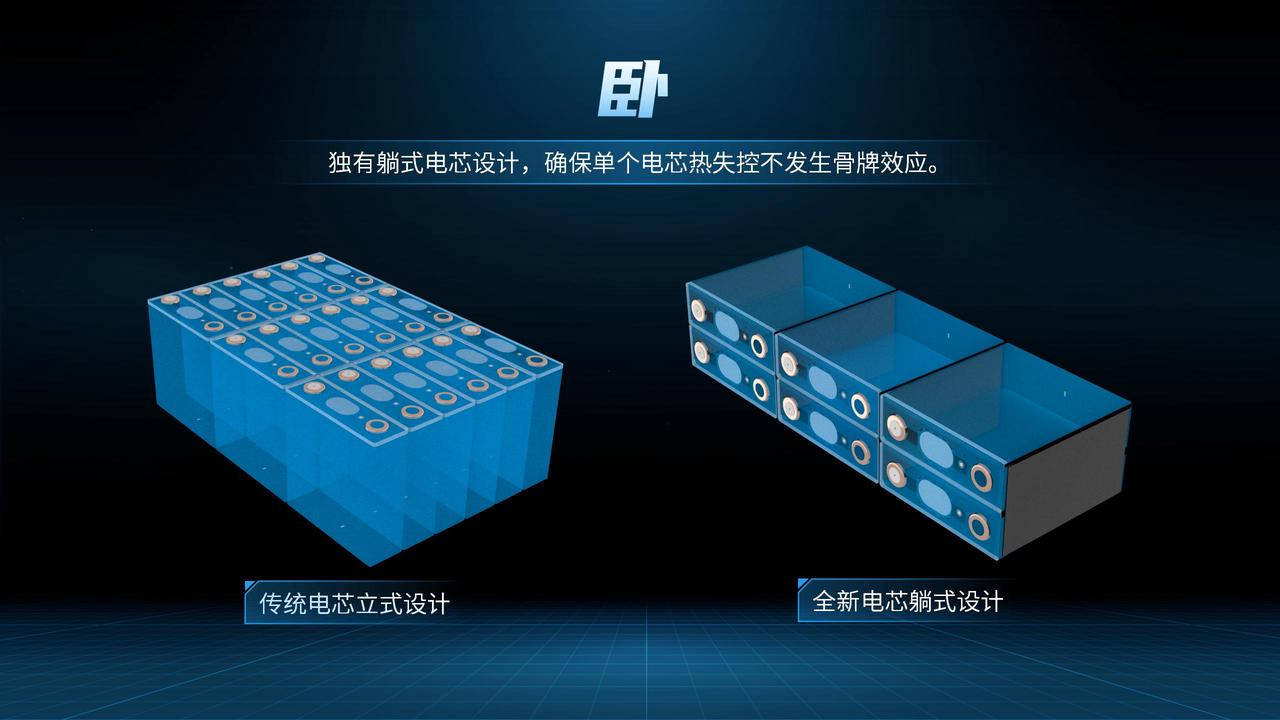
Currently, the mainstream square-shaped battery cells are vertical, and the pressure relief valve of the cell sprays upward. The high-temperature and high-pressure exhaust gas directly impacts the upper cover of the battery. Although this part has been strengthened and a pressure relief channel has been set, it is still very close to our feet.
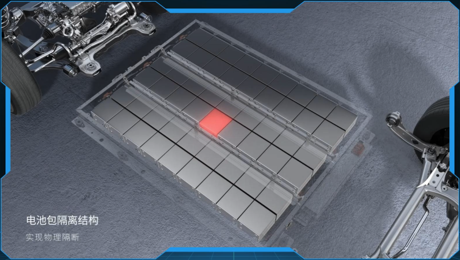
The pressure relief valve of the horizontally arranged battery cell opens on the side, meaning that the exhaust gas will impact the tray on the side.
In the picture above, we can see that the battery pack has four pressure relief channels arranged parallel to the direction of the wheels. The four inner double-layer battery cells share two channels, and the outer cells each have one row of channels.
Considering the mission to protect the physical structure stability of the battery, the structure strength of the outer tray is much greater than that of the upper cover. Therefore, overall, the horizontally arranged cell’s pressure relief valve design is indeed safer in terms of structure.
In addition, horizontally arranged battery cells can reduce the spreading of thermal runaway.
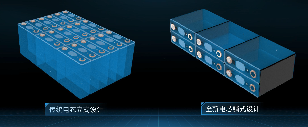
In the design of the cube battery, the thermal runaway of the cell is allowed to be conducted between two stacked cells, and they are housed in a separately isolated “small single room”. The “contact” between them and adjacent battery cells in the “small single room” is the contact area, which can be seen as a narrower side area compared to the large area contact between vertical cells.
Therefore, horizontally arranged cells can to a certain extent prevent thermal runaway from spreading into a domino effect-style collapse.
Why not provide protection for each cell? The first reason that comes to mind for many people is cost, which is indeed correct. However, the most important thing for square-shaped batteries is that it is difficult to increase the energy density of the battery pack.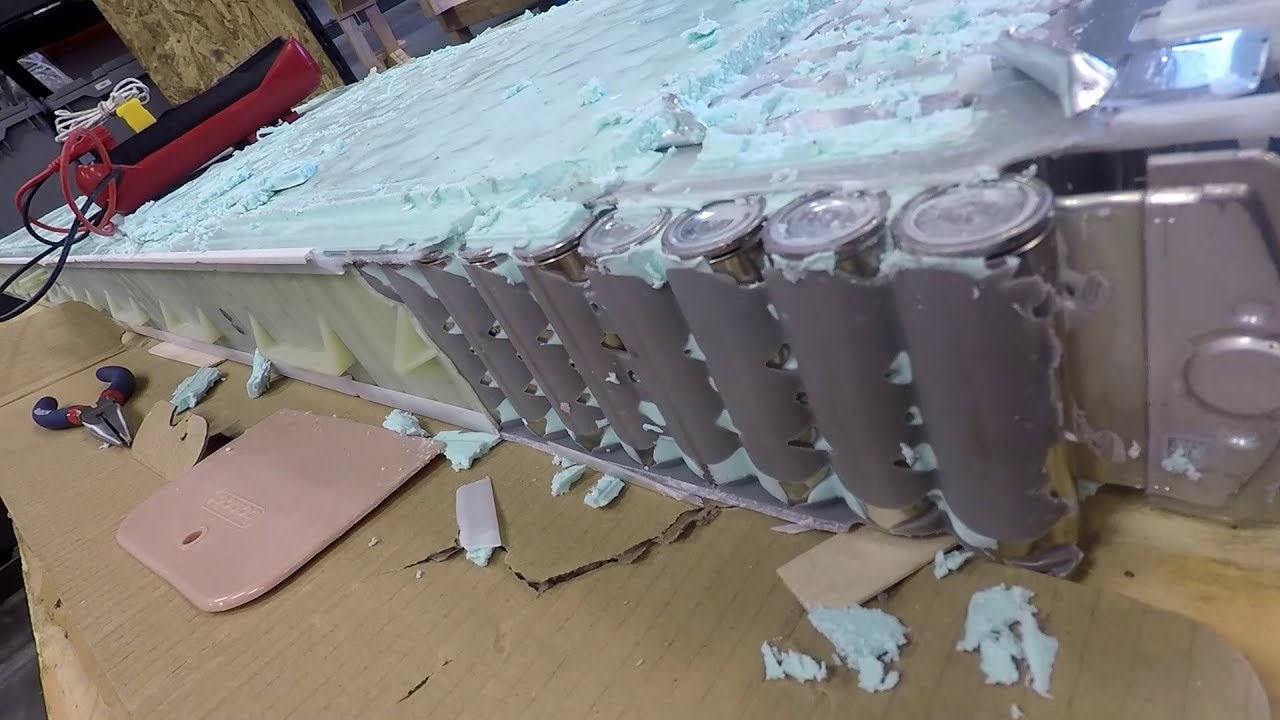
Of course, there are exceptions, such as the battery pack using cylindrical batteries, which will fill special composites between the battery cells.
For example, the domestically produced Voyah pure electric vehicle model uses Samsung SDI’s NCA high nickel 8 series cylindrical battery cells, and their solution is called “Amber”. The flame retardant, insulation materials, and organic silicon materials are comprehensively filled in the battery cell in-between, like amber wrapping the filling. This design could be called a “small single room” or more appropriately a “small bed” for the battery cell.
Of course, when the battery cell stands up, the contact area between the battery cell and the cooling water board is reduced. Then, how to solve the heat dissipation?
The solution for Magic Cube Battery is “Vertical Cooling Structure“, which stands up the original cooling water board and makes it into a vertical cooling water panel. It still takes bottom heat dissipation, but after “lying” down, it becomes a side state.
The final effect is obvious. The Magic Cube Battery has achieved L0-level thermal runaway protection technology, which meets the “Safety Requirements for Power Batteries for Electric Vehicles” GB 38031-2020 proposed by the 2020 National Battery Safety Standard of China. The time for battery system protection after the single-cell heat runaway even reached five minutes.
SAIC Motors itself also conducted a popular needle puncture test. After the needle punctured the battery pack and triggered a thermal runaway, the damaged battery pack emitted smoke but did not catch fire, explode, nor have any thermal spread.
Is the life span enough?
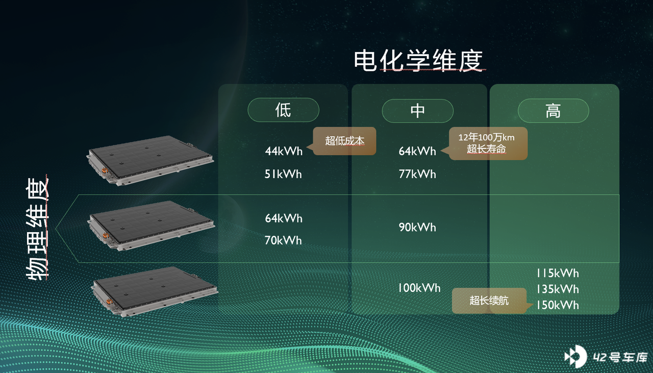
Looking closely at this graph, we can see that the 64 kWh battery is specifically marked with an ultra-long lifespan of 12 years & 1 million kilometers.
In 2015, the Beijing Municipal Commission of Economy and Information issued the “Management Measures for Filing New Energy Small Car Companies and Products in Beijing (2015 Revision)”, which stipulated that:
Provide warranty service for the vehicle for no less than 3 years or 120,000 kilometers. Provide warranty service for critical parts such as power batteries, motors, vehicle controllers for no less than 8 years or 120,000 kilometers.
Therefore, everyone can feel how much the lifespan of this 64kWh battery has surpassed the requirements of many countries. If we look at a replacement cycle of about 200,000 kilometers or three to five years, this battery has even exceeded the replacement cycle of the vast majority of personal consumers.
There are many factors that affect the lifespan of the battery pack, such as the aforementioned thermal runaway control.
The battery cells themselves will also experience changes in volume due to factors such as temperature and charge state, and how to solve this difficulty will directly affect the health status of the battery cells.
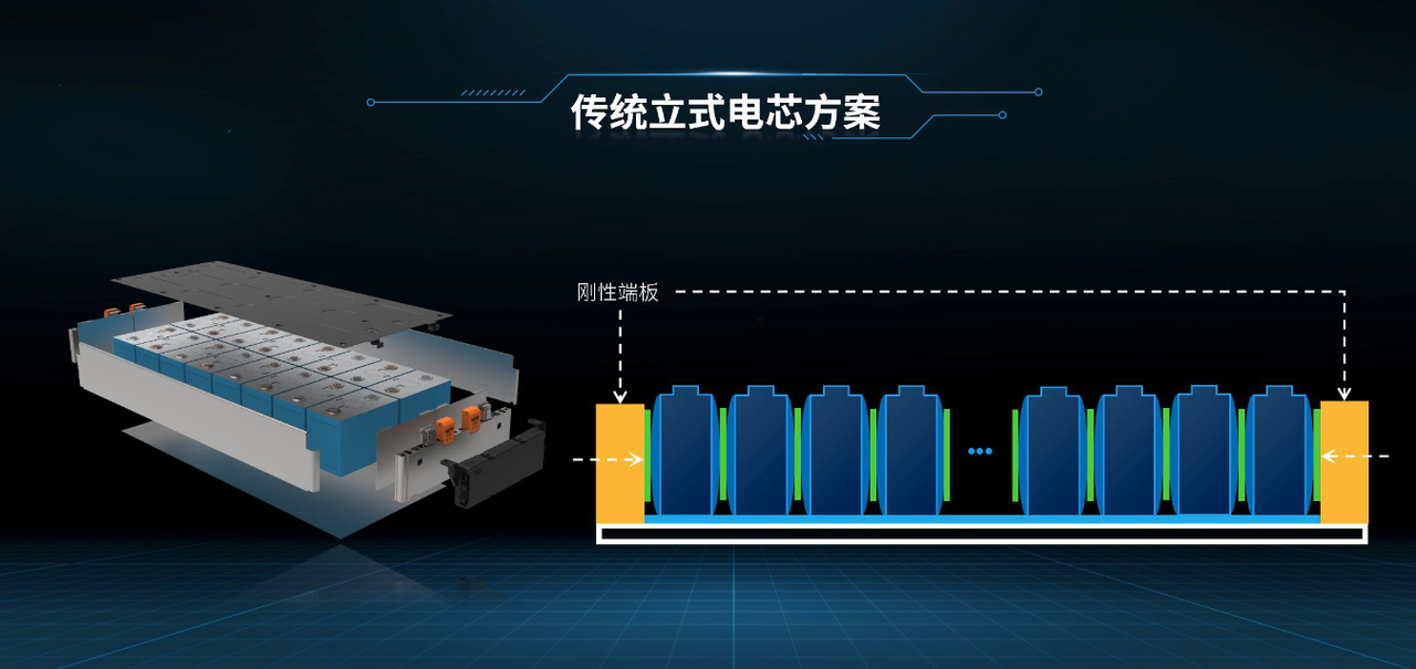
On traditional cylindrical batteries, rigid end plates with small deformation amplitudes are fixed to the batteries to anchor them in place. This means that the volume change of the battery cannot be too large, because if it is too large, it will be compressed by the end plates, which is not good for the health of the battery. In severe cases, the battery may be compressed and ruptured.
As described by Zhu Jun earlier, Mo Fong batteries will be tightened by a floating structure. Throughout the entire life cycle, the different charge states of the battery can fix the battery within a limited range.
We can understand this as “SAIC wants to achieve the shorts that can always fit tightly with the changing figure like the Hulk’s.”
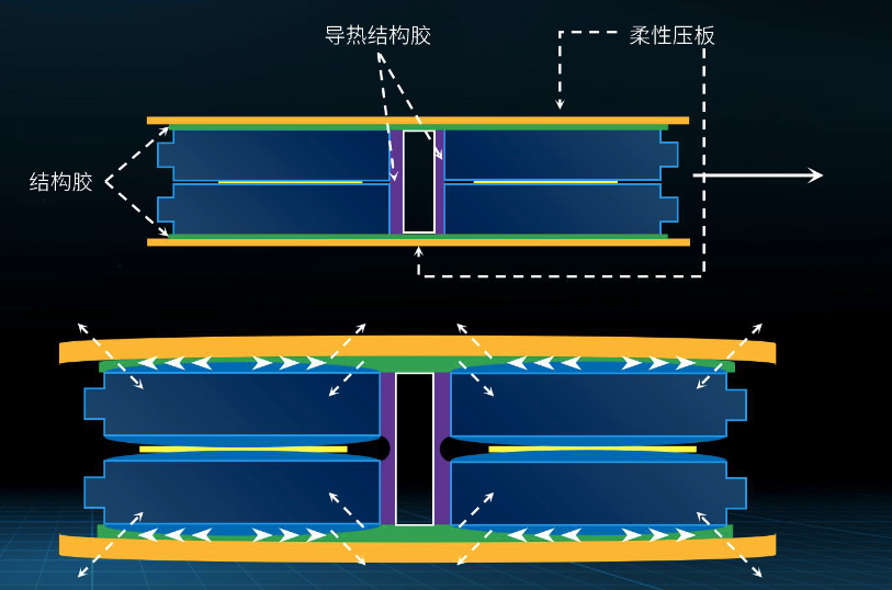
The floating pressure structure mentioned here refers to flexible pressure plates used on the upper and lower layers of the lying battery. The flexibility means that the pressure plates can match the volume changes of the battery. Of course, this is not enough, because the upper and lower layers of batteries will also compress each other due to volume changes. The usual approach is to inject structural glue into them. On the one hand, it can bear the force, and on the other hand, it can also prevent combustion.
How can the structural glue better adhere to the volume changes of the battery? SAIC chose to jointly develop a structural adhesive for the lying battery with Dow Chemical, a leader in the chemical industry.
Ultimately, the structural deformation of the Mo Fong battery achieves the self-adaptive effect of “Hulk’s elastic pants,” which also becomes an important reason for extending the battery life.
At the end
On the previous MG MULAN, the Mo Fong battery used was a battery pack with a thickness of 110 mm and “low” degree battery packs of 51 and 64 kWh. The 125mm thickness 108 string 90 kWh “medium” Mo Fong battery pack is applied on the Roewe iMAX8 EV. As a pure electric MPV, the net height inside the Roewe iMAX8 EV can reach 1,020mm, and most of the reason is the slim Mo Fong battery.
This is a demonstration of the advantages of the Mo Fong battery. According to SAIC engineers, the “gradual utilization” of the Mo Fong battery is a way to match different chemical formulas, energy densities, and thicknesses according to different vehicle requirements. When we extend this to the battery swap layout that SAIC is currently deploying, this gradual utilization will also cover various usage habits and better vehicle residual value in multiple scenarios.The non-traditional layout of the Magic Cube Battery lying battery cell comes with many advantages and changes. On June 23, the leading battery company, CATL, also adopted the non-traditional “inverted” cell arrangement with the release of the “Kirin Battery”. This breakthrough, coupled with CTC and CTP technology, enhances the available capacity of the battery pack, and at the same time develops other advantages, which is a good skill to have. The subsequent pressure will be on the production side.
Related reading:
- Battery cost reduction by 50%, 12 million sales target in the Chinese market by 2025, Volkswagen’s battery technology route exposed – Garage 42
- After Trillion-dollar Market Cap, Why is CATL Making Sodium-ion Batteries? – Garage 42
- CATL’s Kirin Battery Released, Ideal has been booked for next year? – Garage 42
- You have your blades and magazines, I have “Dayu” to help – Garage 42
- MG CEO Zhang Liang: MG MULAN is benchmarking Model 2 – Garage 42
This article is a translation by ChatGPT of a Chinese report from 42HOW. If you have any questions about it, please email bd@42how.com.
