Author: Panjiang
Smart Chassis Series (1) | Yesterday, Today, and Tomorrow of Smart Chassis
Smart Chassis Technology (2) | Overview of the Development of Car Braking System
Smart Chassis Technology (3) | Starting from Vacuum Booster
Smart Chassis Technology (4) | Introduction to Line Control Brake eBooster
Smart Chassis Technology (5) | Evolution of Chassis Electronic Stability Control System, ABS
With the development of the automotive industry, cars are getting heavier and faster. These changes not only pose higher requirements on the basic braking ability of the car, but also pose higher challenges to the stability of the vehicle. According to research on car safety, about 10% of accidents in road traffic accidents are caused by deviations from the predicted trajectory or fishtail during braking. It is well known that improving the braking performance of the chassis is an important measure to reduce traffic accidents, and active intervention in braking is the key to improving braking performance.
Although the theoretical research on actively intervening in the braking system to improve vehicle stability has been carried out early on, its actual implementation depends on the right time and conditions. The widespread application of hydraulic braking systems to replace traditional mechanical braking and the development of electromechanical technology have provided a technical basis for achieving active intervention in braking and even driving or suspension. Thus, from the early Anti-lock Brake System (ABS) to today’s Vehicle Dynamics Control (VDC) and Electric Stability Controller (ESC), the evolution of chassis electronic stability systems has started in a splendid way.
However, the evolution of chassis electronic stability systems has not stopped yet. The new E/E architecture of smart chassis has brought new optimization directions to the chassis electronic stability system. For example, under the control of the chassis domain controller, cooperative work of various subsystems can achieve faster stability control. Smart chassis and electronic stability systems have become the research hotspots of major OEMs and suppliers.
Against this background, the next few issues will explore the evolution of electronic stability systems and the new directions that smart chassis brings to electronic stability systems based on the following architecture. This article will introduce part 2.- Part1: ABS: Principles of Anti-lock Braking System
- Part2: TCS: Principles of Traction Control System
- Part3: ESP: A Revolutionary Product
- Part4: Outlook: Development of Intelligent Chassis and Electronic Stability Systems

Traction Control System (TCS)
In the previous issue, we introduced the principles of the Anti-lock Braking System (ABS). ABS is activated when the driver steps on the brakes causing the wheels to have a tendency to lock, making it impossible to control stability under non-braking conditions. However, there are also non-braking instability conditions in daily life, such as:
- Condition 1: In the case of accelerating from a standing start on an icy surface, no matter how much the accelerator is depressed, the vehicle cannot move forward.
- Condition 2: When accelerating from a split surface (one tire on a surface with low adhesion coefficient and the other tire on a surface with high adhesion coefficient), no matter how much the accelerator is depressed, the vehicle cannot move forward.
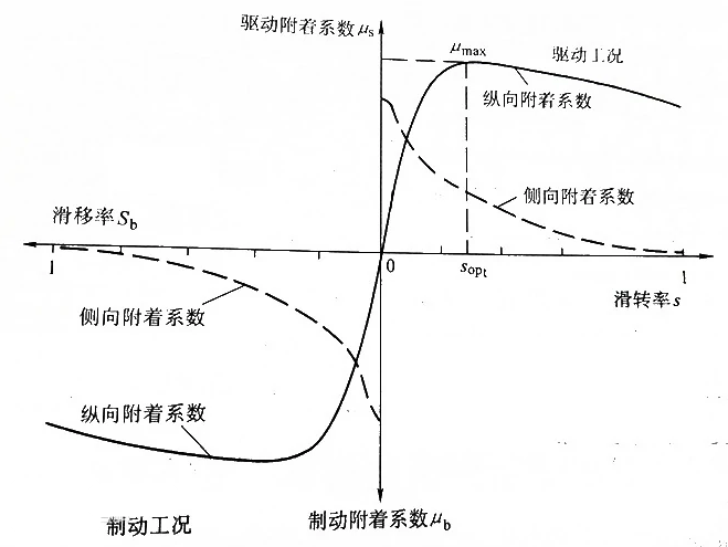
For Condition 1, the reason is that excessive driving force causes the driving wheels to slip excessively, making it impossible to make reasonable use of the road adhesion. Similar to braking, when the tire end exerts driving force, there will be relative motion between the tire and the ground, and the proportion of the sliding component in the wheel is called the slip ratio (which corresponds to “slip ratio” for braking), also represented by S. As can be seen from the figure below, when the slip ratio is controlled within a certain range, the vehicle can maintain good longitudinal and lateral adhesion coefficients with the road surface, thereby providing the optimal driving force for the vehicle.
For Condition 2, it is due to the “side effect” of the differential. The ability of a car to turn depends on the differential. During turning, as the left and right wheels of the vehicle have different radii, their rotational speeds are not equal. If the left and right wheels are rigidly connected, it is impossible to achieve unequal rotational speeds. The differential is a mechanism that allows the left and right drive wheels to rotate at different speeds.
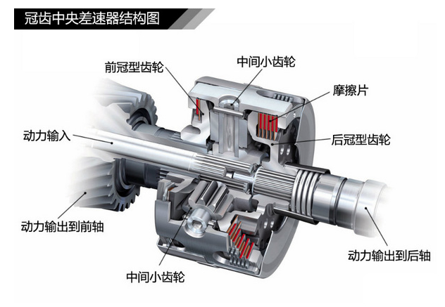
The differential mainly consists of left and right half-axle gears, two planetary gears, and a gear frame. The feature of this mechanism is that the torque transmitted to the two drive wheels is the same, although the rotational speeds of the left and right drive wheels are different.When the vehicle starts on a separate road, the driving wheels on the low-adhesion road reach the adhesion limit first and limit the driving torque transmitted to the high-adhesion side, which is equal to the driving torque on the low-adhesion side. Therefore, the vehicle cannot start due to insufficient driving force.
To solve the stability problems of these two typical working conditions, major mainstream car companies have successively carried out explorations. In 1985, Volvo installed an electronic traction control system called ETC (Electric Traction Control) on the Volvo 760 Turbo, which was the world’s first application of a traction control system on a real car. In 1986, Chevrolet of General Motors installed a traction control system on the Corvette Indy car. In September of the same year, Mercedes-Benz and WABCO jointly developed a TCS system applied to trucks. In December of the same year, Bosch introduced the TCS with braking anti-lock and driving anti-slip functions for the first time——Bosch ABS/ASR 2U, which integrates an anti-lock brake system and traction control system into one and applied it to the Mercedes S-class car, and began small-scale production, marking the advent of the era of ABS/TCS integration.
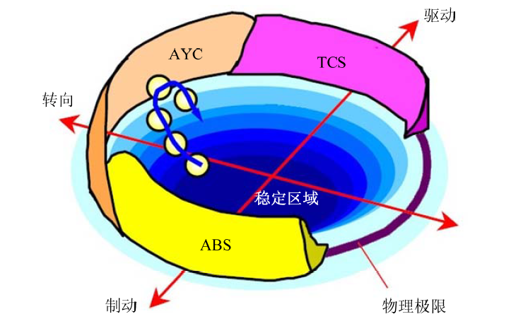
The TCS control system was developed based on the ABS, which works on excessive braking, and the former works on excessive driving. Since TCS can not only adjust the braking pressure, but also adjust the driving force of the engine or drive motor, its components are relatively more than ABS, in addition to the actuator increasing the driving force control unit (engine ECU or motor ECU), it also increases the steering wheel angle sensor and inertial sensor.
① Hydraulic control unit
② Wheel speed sensor
③ Steering wheel angle sensor
④ Inertial sensor (yaw rate, longitudinal acceleration, lateral acceleration)
⑤ Driving force control unit (connected via CAN)
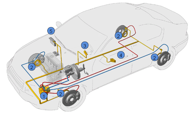 # TCS Control System Architecture
Through the coordinated control of the output torque of the engine or electric drive motor and the wheel cylinder pressure, TCS adjusts the slip ratio of the drive wheels to improve the adhesion characteristics between tires and road surface, and enhance vehicle power and stability. Currently, the mainstream TCS system control architecture is shown in the following figure. The TCS controller mainly includes three parts:
- Road condition identification
- Drive torque control
- Pressure control
The road condition identification module mainly includes adhesion identification and slope recognition. Based on the vehicle state parameters, the adhesion and slope are identified to provide data support for torque control and pressure control. The drive torque control module includes both PID torque control and fuzzy logic torque control. The input parameters are vehicle state and road condition recognition module-recognized road adhesion and slope, and the output parameters are target torque and insufficient torque reduction. The input of the pressure control module is vehicle state, road condition, and insufficient torque reduction output by the torque control module. The pressure control module includes upper and lower pressure control, where the upper pressure control gives the target pressure and the lower pressure control is responsible for its implementation.
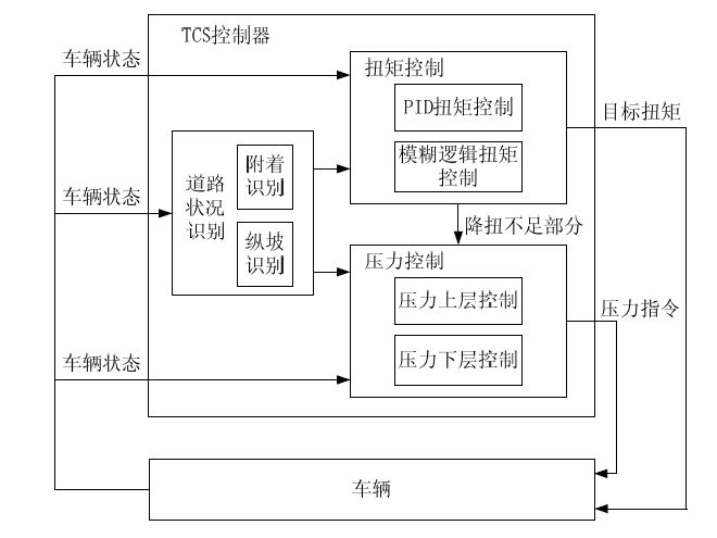
According to the two typical operating conditions, TCS control of the actuator can be classified as follows:

For case 1, when the adhesion coefficients of the two driving wheels are approximately the same, TCS only controls the driving force. The closed-loop control can be summarized as follows:
- The driver presses the accelerator and brake to establish the driving force
- The sensor provides wheel speed, slope, and other information to the TCS ECU. The ECU calculates the slip ratio. If it exceeds the set stability threshold, TCS intervenes and intervenes in the driving force to reduce the driving force and send the target to the driving force control system ECU.
- The driving force control system ECU responds to the target driving force to keep the slip of the driving wheels within the stable range, ensuring that the vehicle can effectively utilize the adhesion force of the road surface.
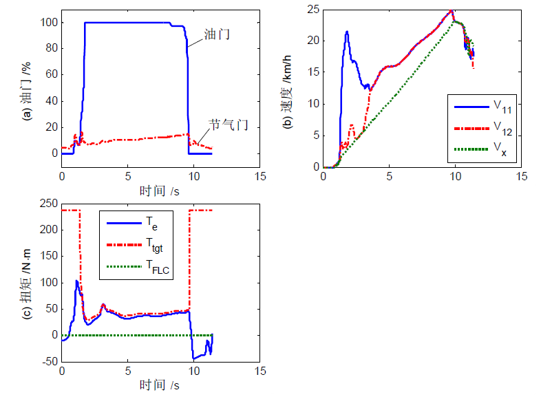
Typical TCS real-time control data under case 1 are shown in Figure 1-10s. From figure (c), it can be seen that TCS limits the engine torque. From figure (b), it can be seen that the vehicle has good acceleration performance when starting on ice, and the vehicle speed is basically stable.
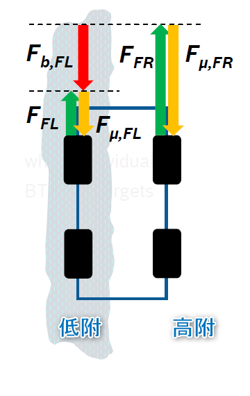
For condition 2, when the difference in adhesion coefficients between the two driving wheels is significant, the maximum driving force that the entire drive shaft can provide is limited by the adhesion coefficient of the lower adhesion side, which restricts the control range of TCS on the driving force, resulting in the inability to adjust the slip ratio to the stability range. In this case, TCS needs to apply braking force to the low-adhesion side wheel while controlling the driving force. As a result, due to the offset of the braking force, even if the driving force on the drive shaft exceeds the adhesion limit of the low-adhesion side, the actual driving force acting on the low-adhesion side is reduced rather than reaching the adhesion limit, which widens the control range of TCS on the driving force of the high-adhesion side wheel and effectively utilizes the adhesion force of the road surface for starting.
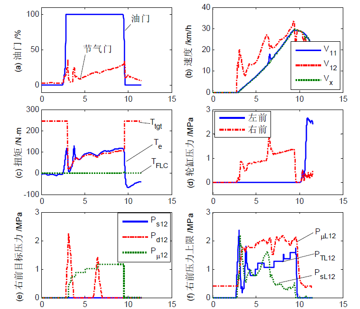
Typical TCS control data for real vehicles under condition 2 are shown in Figure 2-10s below. From Figure (b), it can be seen that when starting on a separated road surface, the low-adhesion side wheel maintains a certain amount of slip, while the high-adhesion side wheel hardly slips, and the acceleration performance is good, with almost no speed fluctuation, indicating good power performance and smoothness on the open road surface. From Figure (c), it can be seen that TCS limits the engine torque. From Figure (d), it can be seen that during the acceleration phase, only the low-adhesion side wheel has pressure, and it maintains continuous pressure, which allows the high-adhesion side to have better adhesion utilization.
This article is a translation by ChatGPT of a Chinese report from 42HOW. If you have any questions about it, please email bd@42how.com.
