Author: Zhu Yulong
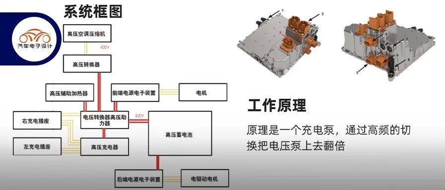
In the designs of Porsche and Volkswagen, the 800V system needs to be backward compatible with 400V fast charging piles. This means that a compatibility boosting system needs to be configured in the car. When designing Taycan, multiple voltage systems were considered in the overall vehicle system, including 800V (power battery), 400V, 48V and 12V (LFP battery). This requires multiple DCDC conversions to convert the voltage to 400V, 48V, and 12V. The charging pump is a key design element.

Considerations for designing high-voltage boosters
The principle of Taycan’s 400V to 800V high-voltage charging system is somewhat complex. The idea was to create an independent system which works like a charging pump. It doubles the voltage by using a high-frequency switching strategy. The system does not require a coil and directly provides the real-time voltage needs of the external DC charging station. The charging pump is designed with a 60Hz control frequency. The circuit is first charged with C1 and C2, and then connected in series with the voltage source through C1, allowing the output voltage to be twice the voltage minus the voltage drop of the diode.
 ### Basic Principle
The basic principle of this product is that the 400V to 800V voltage range is an independent component system, which does not use components of the original powertrain assembly, but rather specialized components.
Detailed Design Plan
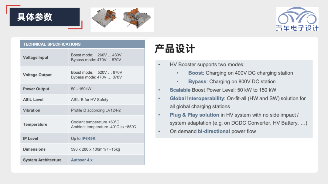
From the perspective of component design, this product has an input voltage range of 260-430V in the low voltage section (boost) and 470V-870V in the high voltage section (bypass), and the corresponding output voltage range mainly depends on the battery’s needs, with the entire power range being 50-150kW.

The most important components in this part are the power module and the capacitor, used in conjunction with an EMI filter capacitor.

Within this component, there are two modes: boost and bypass. Therefore, it needs to be integrated with the PDU, and the entire logical control part is based on Aurix. The yellow part below is high-voltage, while the green part is the control part (low-voltage). This system architecture also works with the battery system.
 Here is the Markdown translation in English with HTML tags preserved:

After the external DC voltage input, it enters the main EMI filter and then connects to the DC capacitors (C1 and C2). With the IGBT module (switches and diodes), it can boost smoothly.
Summary: This boost system from 400V to 800V is a good design for many 800V systems, mainly decoupling from the original system, and the entire design is relatively reliable. The time is tight, so this is all we can write for now.
This article is a translation by ChatGPT of a Chinese report from 42HOW. If you have any questions about it, please email bd@42how.com.
