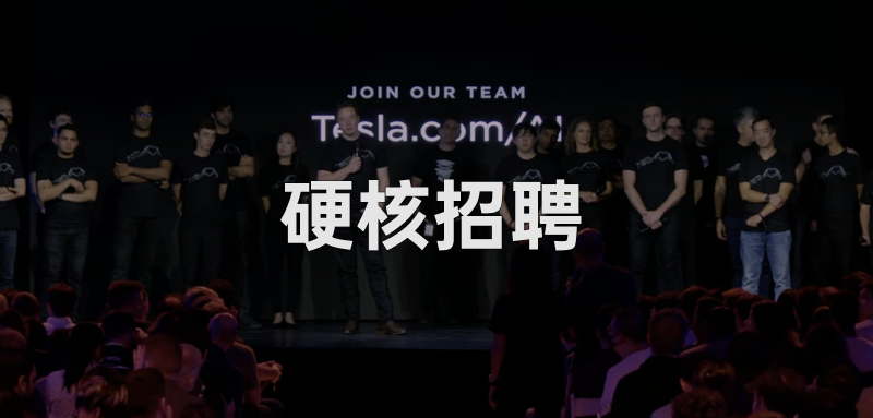
The Introduction of Tesla’s Optimus Robot on AI Day 2021
It has been some time since the term “AI” entered our daily lives. However, many people may still be wondering today about the value and benefits that AI has brought to human society.
In brief, AI refers to the technology that enables computers to perform intelligent tasks, such as recognizing and thinking like humans.
For example, driving like humans.
In 2021, Tesla held its first AI Day, which revealed many technical details about the Full Self-Driving (FSD) Beta. After releasing the FSD chip for autonomous driving in 2019, Tesla also introduced Dojo, a self-developed supercomputer system for machine learning training, and a humanoid robot Tesla Bot. The quantity of the information revealed, as well as the strength of the technologies showcased, impressed the global peers.
Later, Elon Musk provided a more specific time commitment for full self-driving: “I would be very surprised if Tesla has not achieved Full Self-driving in 2022.”
Musk has made similar commitments over the past few years, with either delayed or postponed releases. There are still two months to go before 2022 ends, and AI Day 2021 brought new progress to this question.
However, Tesla first showcased their engineering prototype humanoid robot called “Optimus” in this year’s event.
Optimus: Tesla’s “Humanoid” Robot
As the curtain with the machine-hand-heart pattern was slowly unveiled, the robot appeared on stage without a shell, with wires and circuit boards exposed. It walked two rounds and greeted the audience before standing silently on the stage. Although the speed of its movements was not fast, its remarkable bio-mimetic design could be clearly seen.
This is Tesla’s Optimus, a humanoid robot that is not yet complete but was impressive enough for a show.
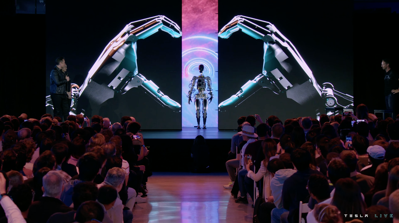
One small detail of the Optimus prototype’s stage debut is that it was its first time performing without any other auxiliary equipment. As Elon Musk jokingly said, one of the reasons why this demonstration was brief was because he was afraid it would fall on the stage later.
However, Tesla’s decision to feature this seemingly funny robot as part of the first segment of the event was not without intent.
Optimus from the “Assembly Plant”Economies of scale are factors that Tesla focuses on in every new product. According to Musk, there are already some well-made humanoid robots on the market, but these robots “lack a brain,” meaning they don’t have enough powerful computing units to function independently in the real world. Moreover, they are expensive and difficult to scale and commercialize.
Take Boston Dynamics, the most famous example. Its robotic dog “Spot” sells for $75,000 per unit, not including additional accessories. Its humanoid robot Atlas currently has not been officially released for sale, but it is expected to cost more than Spot.
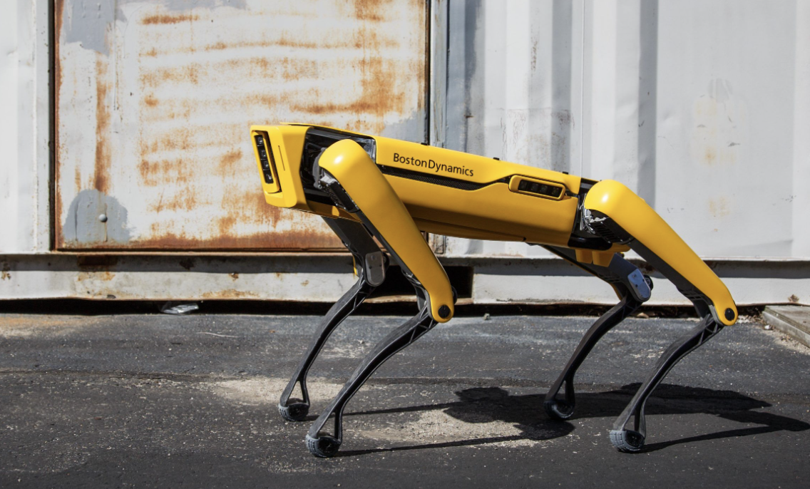
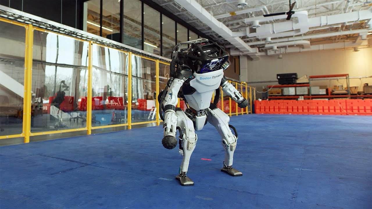
Due to its price and limited practical use, Spot has not become a production force in today’s manufacturing industry, and most people have only seen it in videos.
In Tesla’s robot project, Musk does not want to create an industrial extravagance that amazes people but has no other use. Instead, he envisions the Tesla Bot as a humanoid robot that can create practical value. This concept gives rise to several design considerations:
-
Ease of mass production
-
Low cost
-
High reliability
To achieve these objectives, Tesla has taken a “shortcut” by using its own car parts to build this robot.
Like Tesla’s cars, Optimus provides environmental perception through pure visual algorithms. The sensing device is a camera installed in the robot’s head.


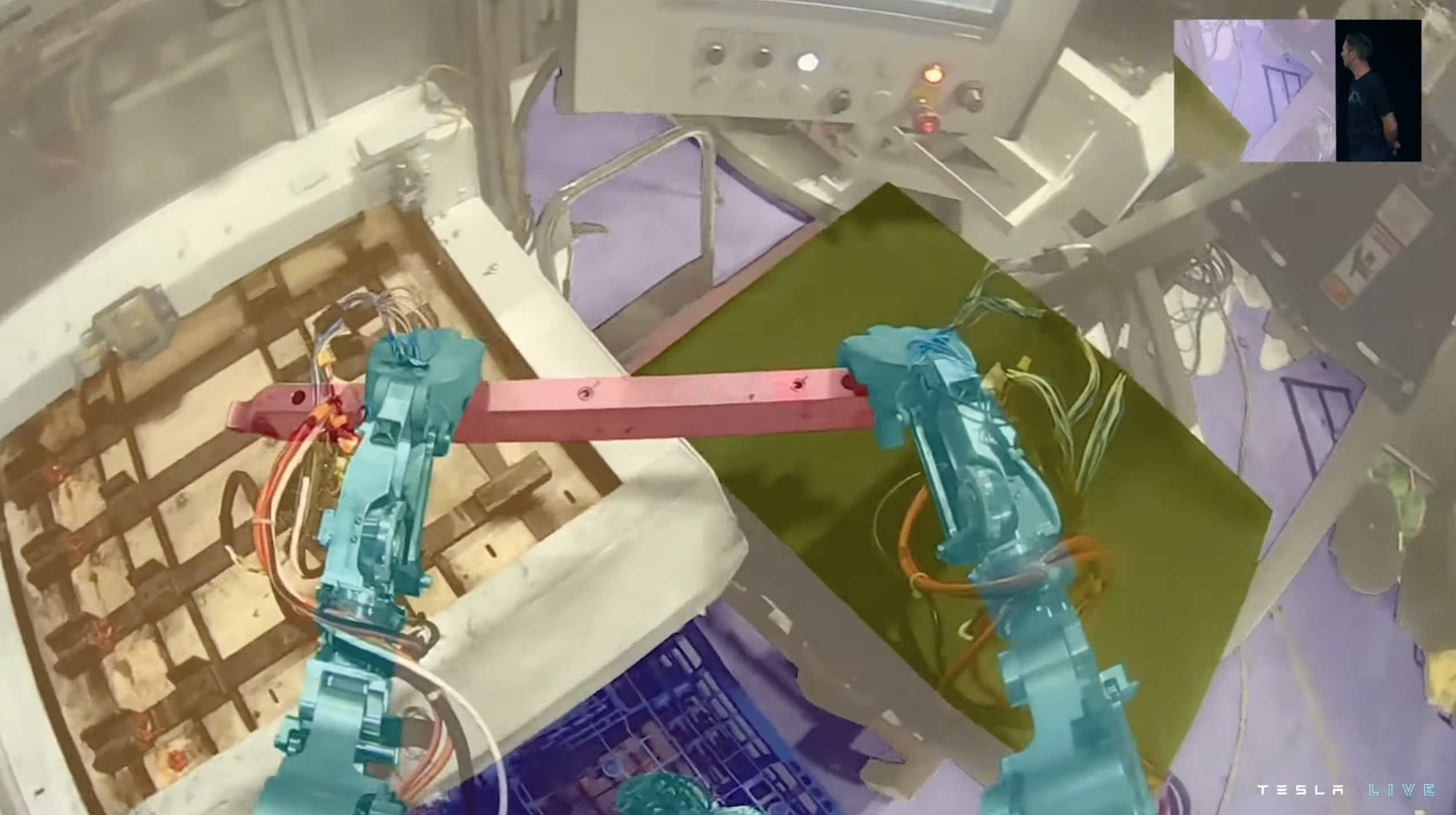
Its “brain” is the same SoC used in Tesla cars, equipped with Wi-Fi, LTE antennas, and audio modules. The robot is powered by a 2.3 kWh battery pack buried in its chest, with a nominal voltage of 52V and using the same cylindrical battery cells as Tesla cars.
To a certain extent, Optimus is “assembled” from Tesla automotive components, with its technical similarity and cost control rationale. Tesla has been using many automotive parts, such as battery cells, inverters, and thermal management systems, in its energy storage product lines.
If there are mature, reliable, and already mass-produced solutions, applying these solutions to more parallel businesses under performance prerequisites is indeed a more efficient and less resource-intensive approach.

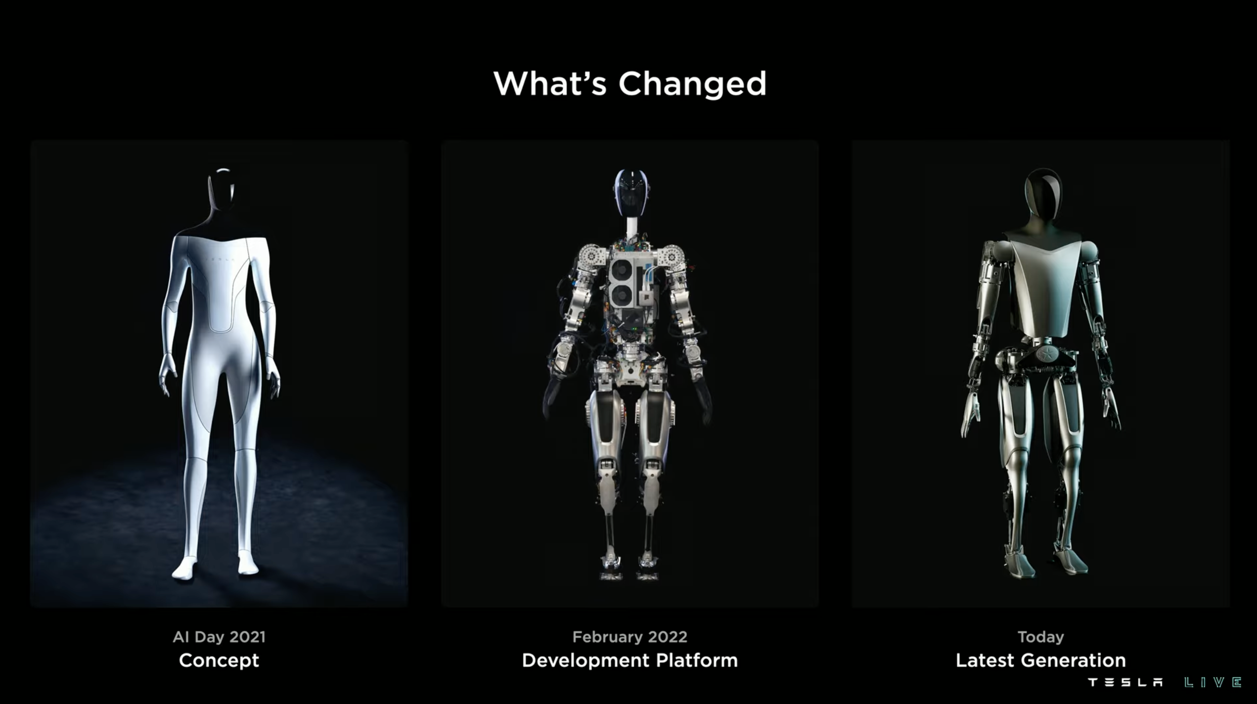
Caption: The evolution of Tesla robots from concept to reality
Human and Robot
Before talking about the technical details of Optimus, Tesla first expressed admiration for the structure of the human body, which reminded me of Andrej Kapathy introducing the FSD visual perception system at AI Day 2021 by first discussing the human visual neural network.
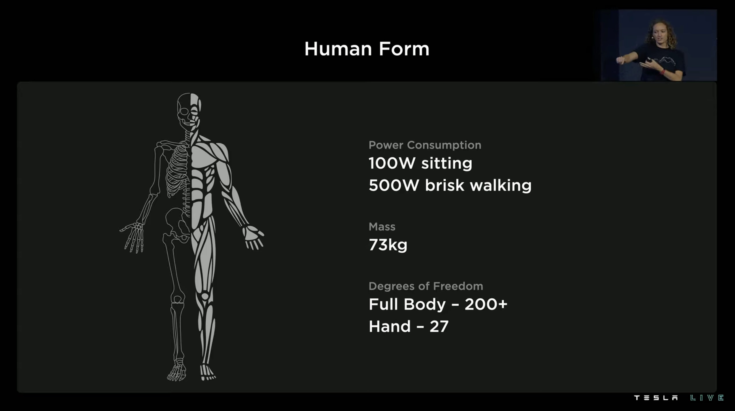
Tesla’s presentation included several parameters of the human body:
-
Energy consumption at rest: 100 W
-
Walking energy consumption: 500 W
-
Weight: 73 kg
-
Over 200 degrees of freedom in the whole body
-
27 degrees of freedom in the hands
The most critical parameters are the last two, and we do not delve deeply into the professional concept of degrees of freedom. In general, degrees of freedom can be understood as “movable ways.” The higher the degree of freedom, the more flexible the body part, which can achieve more movements.If you want robots to be as flexible as humans, increasing the degree of freedom in bionic structures is better. A simple example is when a person sprains their ankle, it affects their ability to walk, which is due to a restriction of the ankle joint’s degree of freedom. However, increasing the degree of freedom will increase the complexity of the system and the difficulty of kinematic control. No one has yet to create a humanoid robot with the same degree of freedom as the human body.
Tesla hasn’t achieved this either, but they took the higher priority 28 degrees of freedom and assigned 11 of them to the hands of their new robot, Optimus.
In terms of thermal management, Optimus’ battery pack no longer uses the S-shaped liquid cooling plate of a Tesla car battery pack. Instead, the thermal management board is attached to the bottom of the battery because the overall power consumption of a robot is not as essential as that of a car, which reduces heat generation. As the robot’s volume is limited, system integration is crucial. For this reason, Optimus has also integrated the battery management system module into the battery pack.
How to make Optimus cheap and sturdy?
In terms of the robot’s anti-drop design, Tesla has once again utilized their simulation analysis software and accumulated data from car crash tests to create a crash-proof board in Optimus’ chest. The robot’s posture is also controlled when it falls so that the board takes the impact when it hits the ground, becoming the robot’s “crash beam” to keep the relatively expensive and difficult-to-maintain arm components from suffering severe damage.

The same mechanical analysis model is also used in Optimus’ actuator design. Tesla will use a validated structural mechanics analysis model to find suitable mechanical inputs for the actuator and add validation for possible subsequent operations, such as walking, climbing stairs, and carrying objects. Then the entire mechanical model is optimized again.
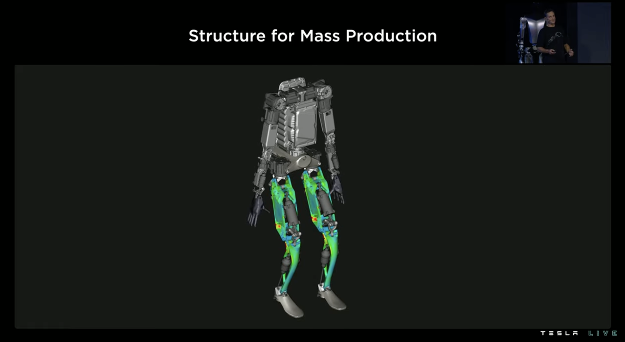
When designing the integrated structural control of the humanoid robot, industry peers usually maximize the robot’s basic motion execution ability to allow the basic motion execution frequency to reach 10 Hz (10 times per second). This enables the robot to have sufficient basic motion capabilities, making the implementation of “walking” easier.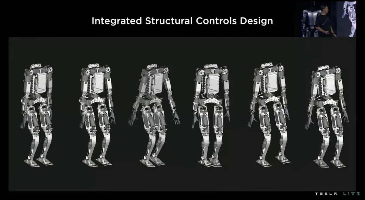
However, Tesla does not believe that Optimus should follow this design philosophy, because Optimus is a robot that needs to be mass-produced on a large scale, with a production volume of millions, and cost should be based on “as cheap as possible while meeting basic needs”. Therefore, even metal materials are not preferred by Tesla, let alone using titanium alloys and carbon fiber composite materials. If plastic can be used to achieve the same goal, then plastic should be used whenever possible.
As a result, while saving money, the mechanical properties of Optimus, such as stiffness, will inevitably be inferior to those of humanoid robots using luxurious materials. However, Tesla subsequently posed a good question: “Do we really need such a high-frequency execution rate for movements? After all, even I cannot shake my leg at a rate of ten times per second.”
Implicitly, since the fastest possible basic execution frequency of the human body is less than 10 Hz, it indicates that various limb movements can also be achieved at low frequencies, but the requirements for the execution control module are higher at low frequencies, which represents an area where software algorithms can be further improved.
This logic reminds me of Tesla’s choices between LIDAR and pure vision. It seems that at every such technology crossroads, Tesla always chooses the approach with the lowest hard cost and the biggest soft cost to make a comeback, which is also an expression of Tesla’s first-principles thinking.
The Four-Link Knee Joint that Does More with Less Effort
Like the falcon-wing doors of the Model X, the knee joint design of Optimus was specifically mentioned at AI Day. Tesla stated that this biomimetic design was inspired by the structure of human knees.
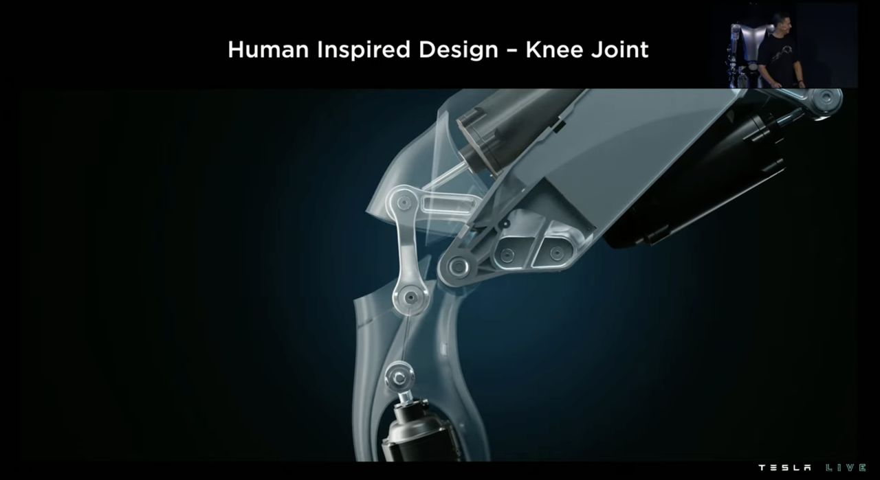

 Compared to simpler pivot designs, this four-bar linkage knee joint, which simulates the human knee joint, can make the mechanical model of Optimus’ legs more optimal, or more “driver-friendly”.
As shown in the PPT, as the bending angle of the legs increases (approaching a squatting posture), the torque required to perform the same task will become greater and greater. To make an analogy, walking in a half-squat position is more challenging than walking in a standing position.
Using a four-bar linkage structure will make the torque required for the same load in both straight-legged and bent-legged positions more uniform and consistent (green line). However, if a simple two-bar design is used, simply connecting the robot’s upper and lower legs with a pivot, the required torque graph will become the blue line, and the torque required in the bent position will increase significantly. The maximum torque required for the driver in the two-bar structure is more than twice that in the four-bar structure. “Using a four-bar knee structure achieves a situation where a small horse can pull a big cart“.
From cars to robots, Tesla has always paid attention to energy management during the driving process. The content that needs to be managed on a car is “relatively simple”. There are at most three motors on a Tesla electric vehicle, but on the PPT, there are more commonly two motors. The working conditions are relatively clear, and the engineering team can set up the motor’s energy consumption characteristics based on the energy consumption map of different working conditions.
However, on Optimus, the number of drivers has suddenly increased to 28. As for working conditions, in addition to standing, walking, turning left and right, and other scenarios that are relatively easy to list, the robot can change its actions and exertion in different ways, with different results. The number and complexity of such scenarios have further increased.
But in fact, the methodology is still similar to that of an electric vehicle. Tesla first records the working diagram of a specific joint driver under a specific working condition, and then compares it with the driver’s own energy efficiency graph to obtain a set of the driver’s energy efficiency data.
Tesla then used the corresponding driver’s total energy consumption performance to be linked to system cost as the vertical axis, and combined with driver weight as the horizontal axis to form a data point in the following figure.
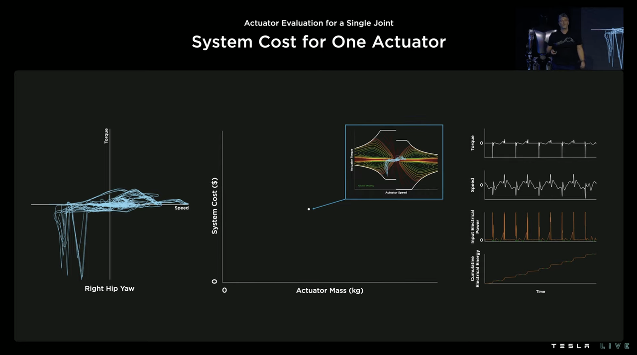
By repeating the same process on more drivers (Tesla claims hundreds), a graph of driver weight and system cost is obtained. The driver that can concurrently consider low cost and lightweight is more suitable as the driver for this joint. For example, the point marked with a red cross in the following figure is the driver that Tesla believes is most suitable as the driver of the right hip rotation joint.
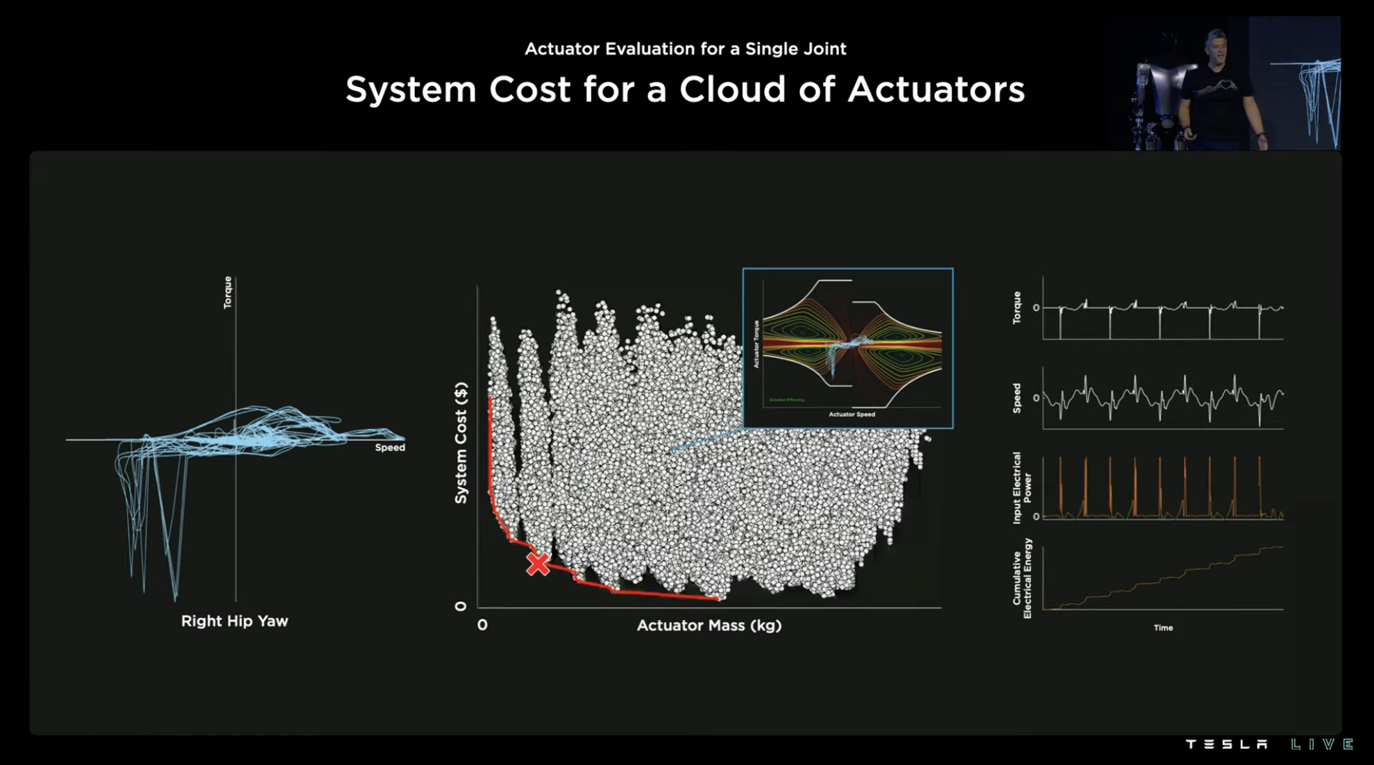
With one joint done, there are still 27 others, so the same process is carried out on all of these 27 joints, and the driver selection for all joints based on the best consideration of cost and lightweight is determined.
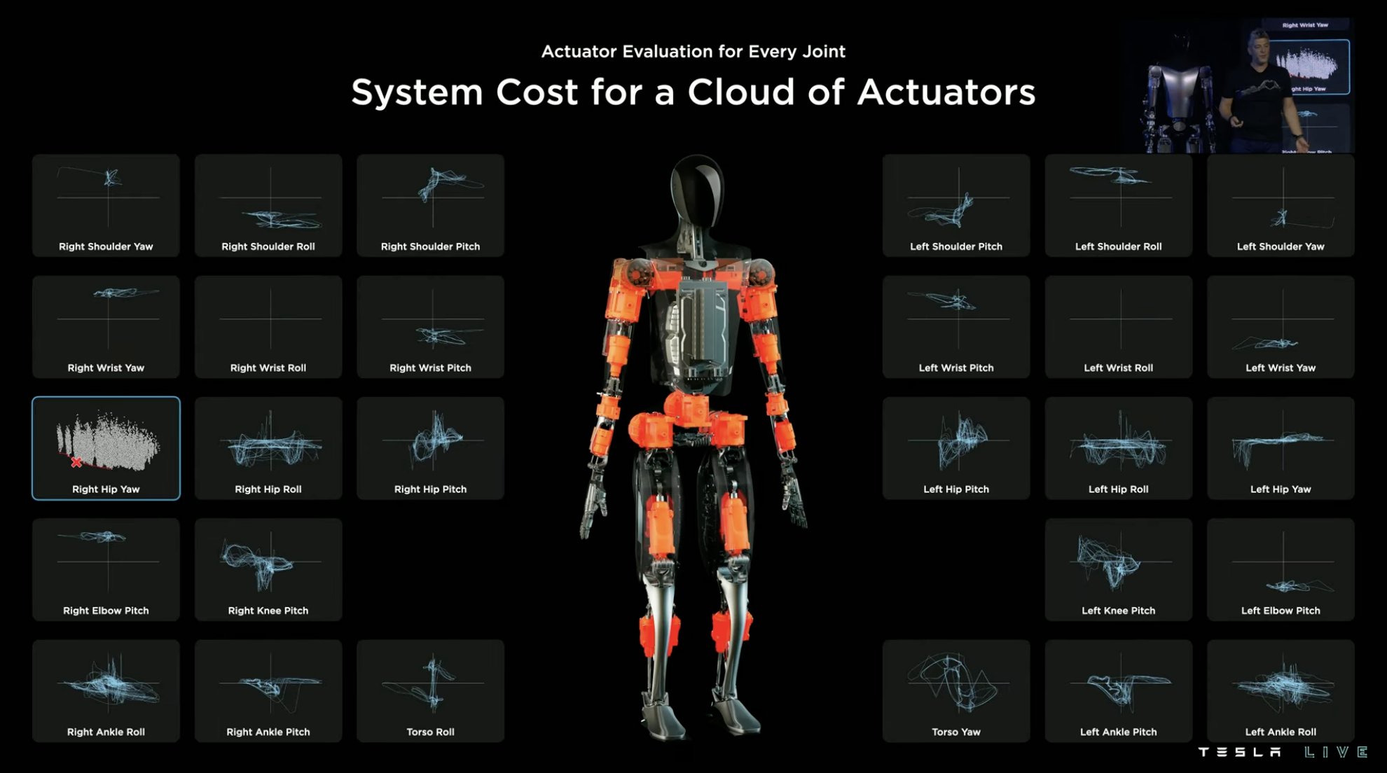
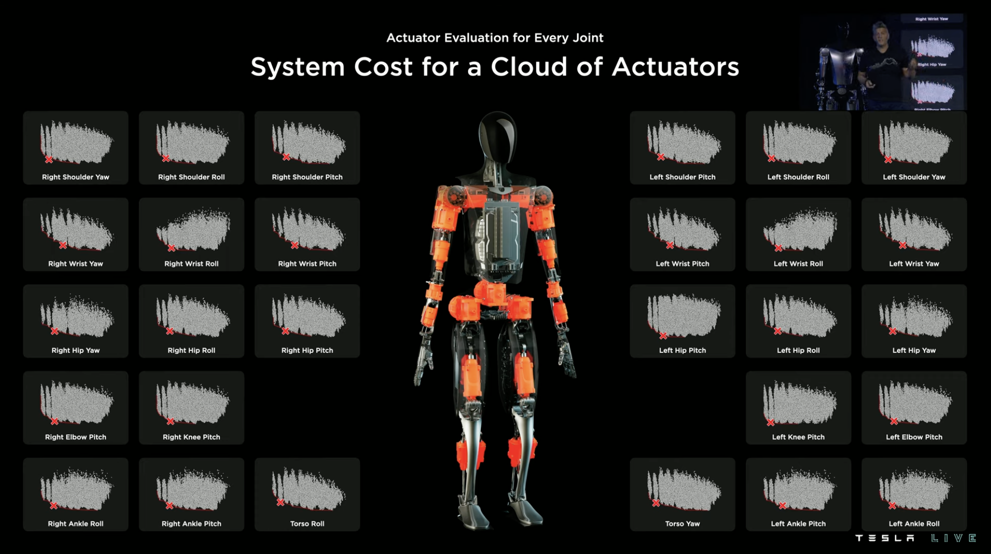
However, Tesla thinks that this is not enough, because even so, there are still too many combinations of driver models within the entire system, some of which are special models with low production efficiency.
So the “downgrade” continues. Based on the previous selection, Tesla conducted a universal interchangeability test on all drivers and found driver models that can be used in multiple joints under cost-weighting guidance within a reasonable range.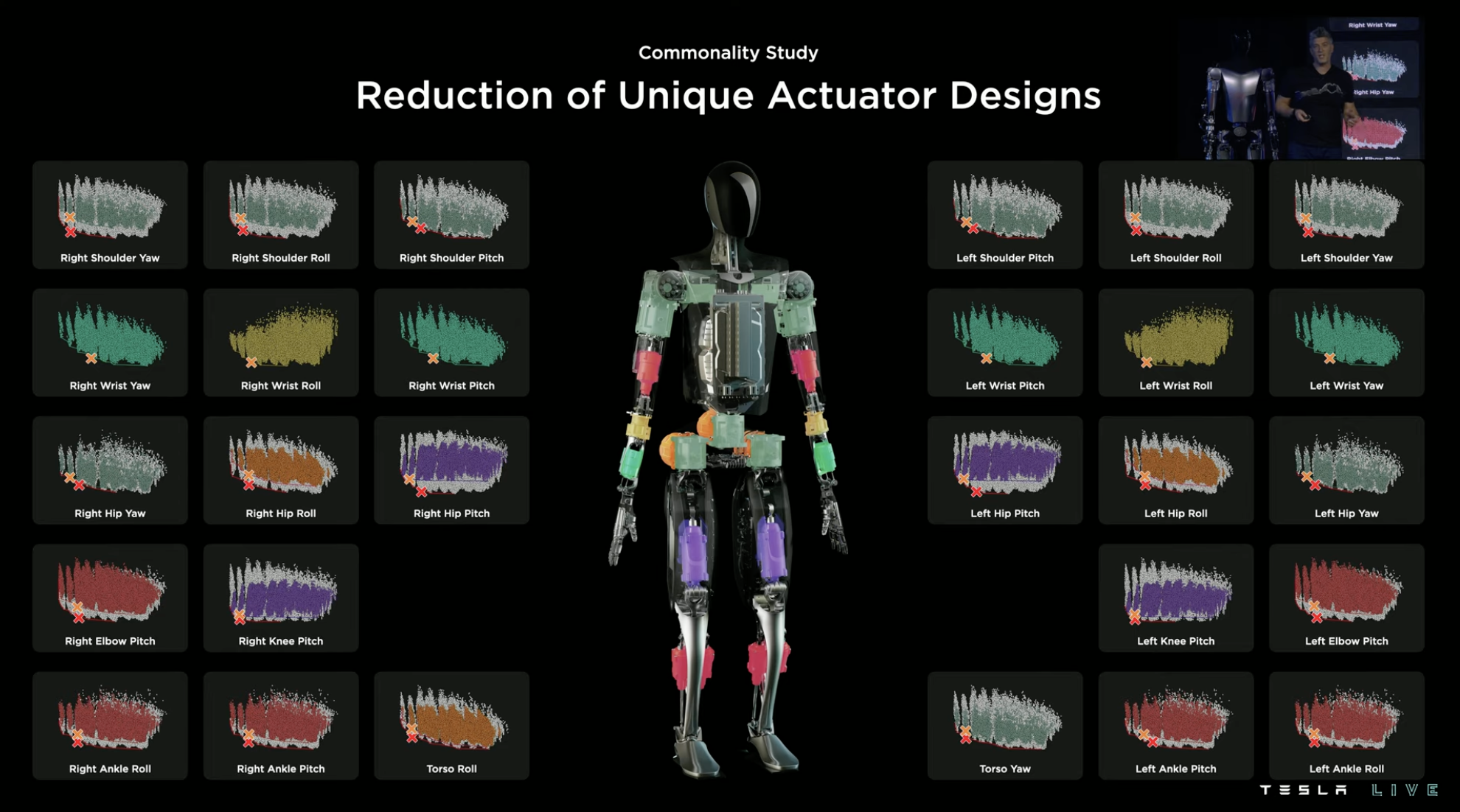
After careful consideration, Tesla has finally selected 6 types of drivers for Optimus including 3 rotary drivers and 3 linear drivers with excellent “torque-to-weight ratios”.
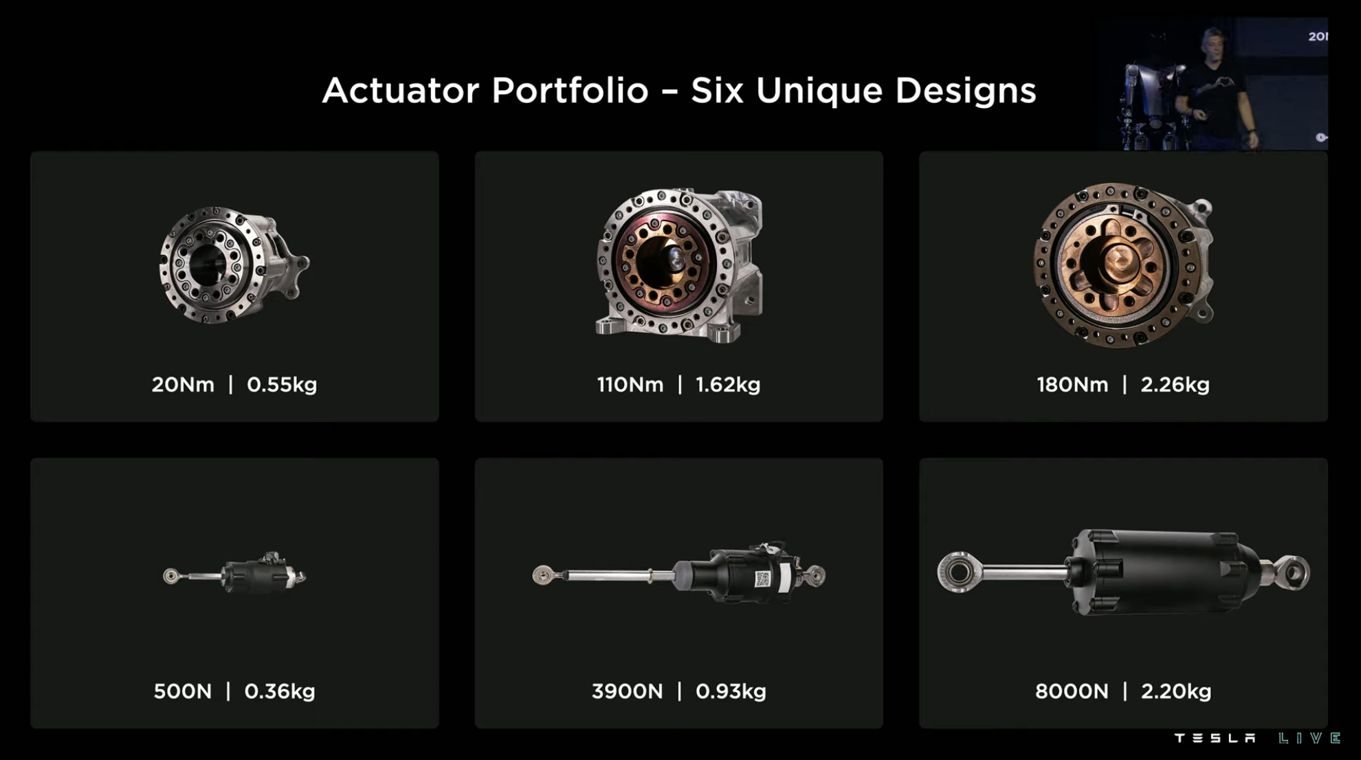
Small Size, Big Power
Tesla pays great attention to the output torque in the design of the driver. Therefore, Tesla uses a mechanical structure of “multi-stroke” to exchange for “large torque” in both rotary drivers and linear drivers of Optimus, such as the inverted ball screw in the linear driver.
Corresponding position sensors and torque sensors are also arranged inside the driver to achieve more accurate electronic control.
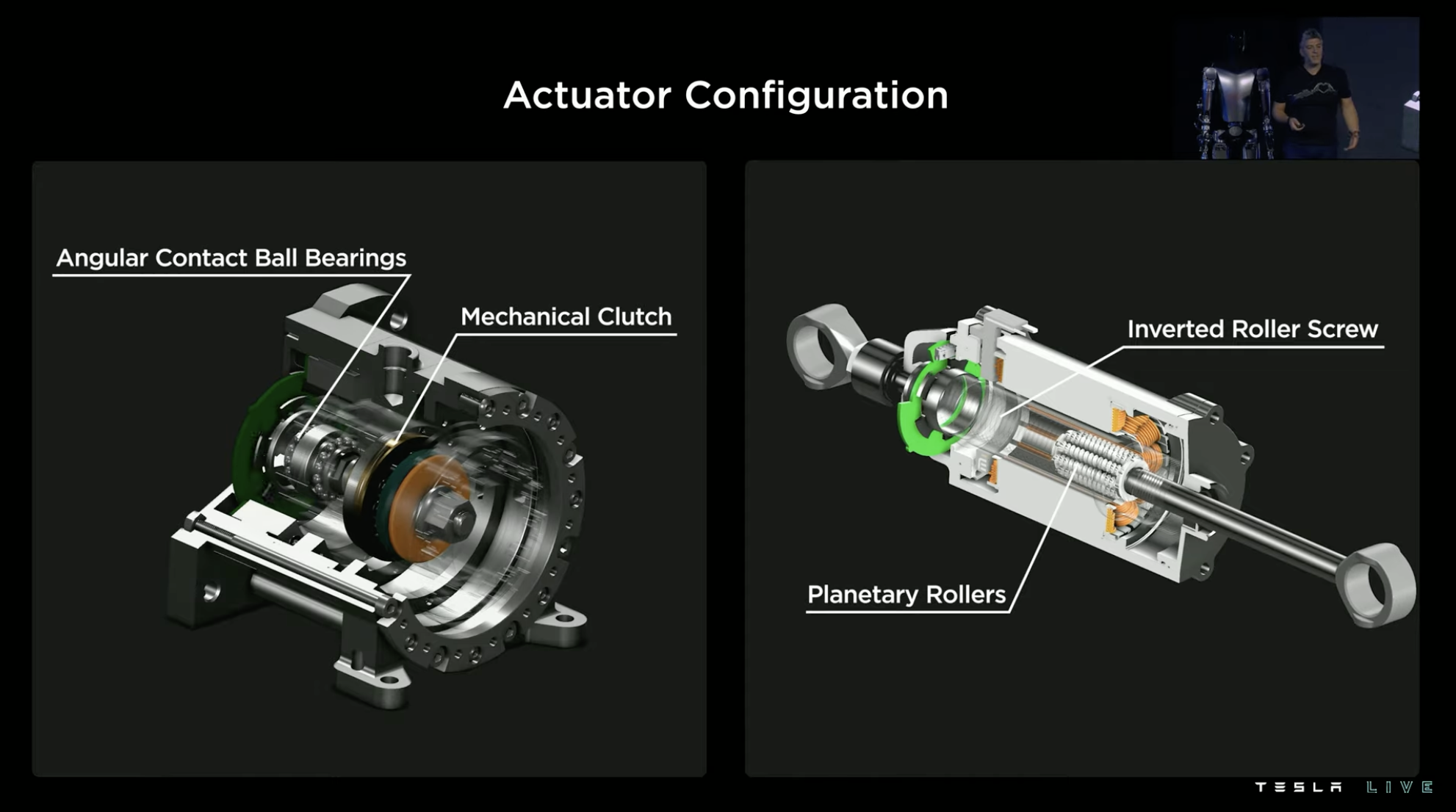
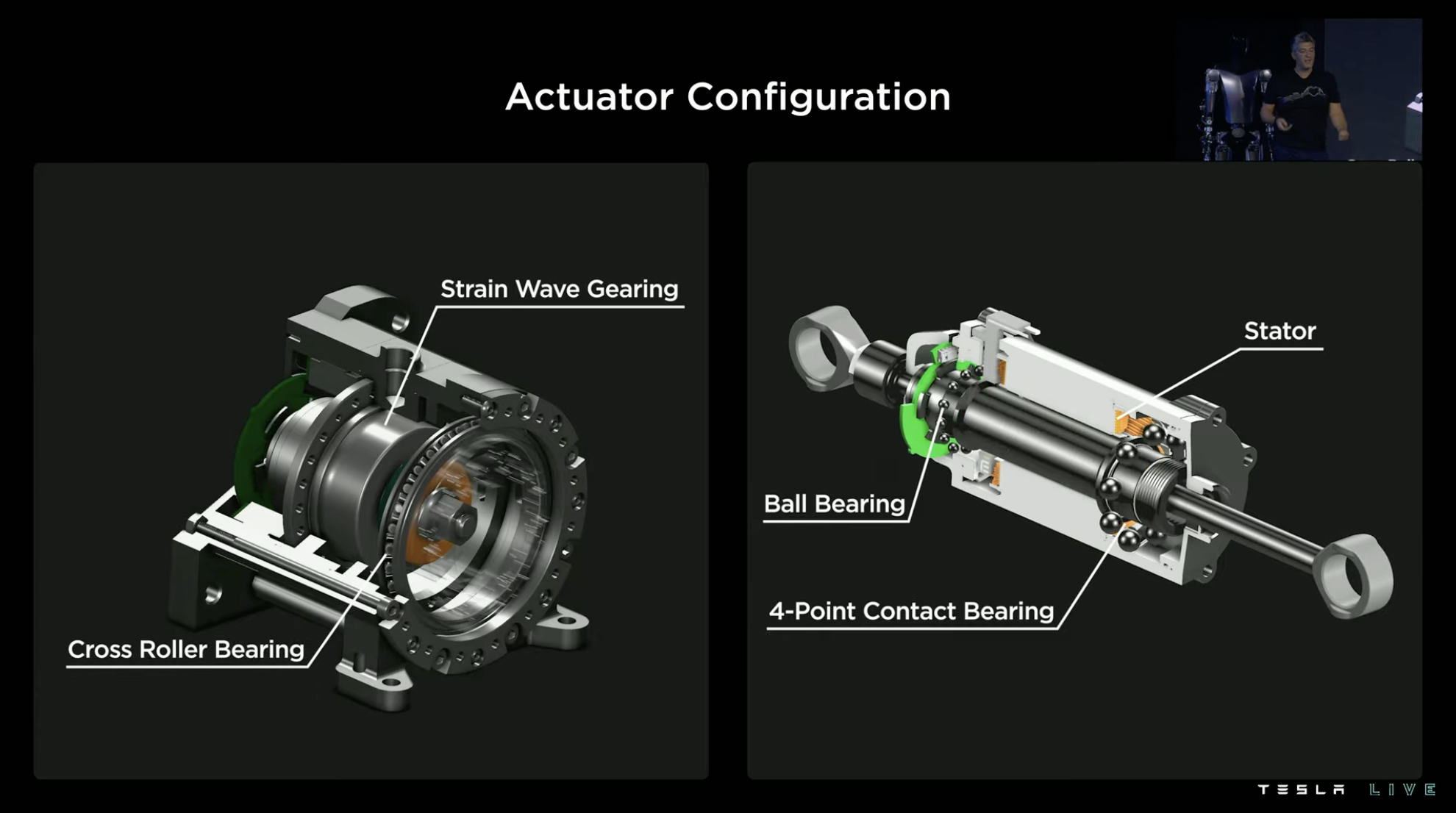

In order to showcase its effects more intuitively, Tesla hung a nine-foot grand piano weighing half a ton as a reciprocating motion demonstration using the linear driver on Optimus, which is equivalent to “gluteus maximus” and “quadriceps femoris” in the human body.

However, after the demonstration, Tesla stated that this is not something to flaunt, but a necessary indicator for humanoid robots to “become human”. The muscles corresponding to the parts of our body have similar strength under the direct connection of the load, but we exchange torque for higher speed ability after amplification through joint amplitude, and therefore, the human body can have outstanding physical ability and agility.
Building a Flexible Robotic HandThe process continued and before introducing the hand design of Optimus, Tesla once again praised the incredible capabilities of human hands:
-
They can easily rotate 300° in just one second;
-
They have tens of thousands of tactile sensors;
-
They can grasp almost any object in daily life.
Moreover, there are a large number of items in human society designed for easy human use, especially for ease of use by hand, so the hand design of Optimus once again adopted the concept of biomimetics. This sentence reminds people of the reason why Tesla focuses on visual perception for FSD: because all roads in the world are designed for human driving, and people rely on vision to drive.
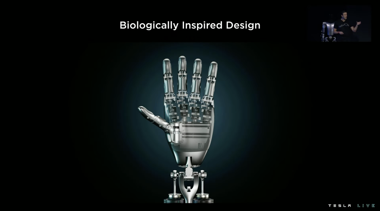
Each hand of Optimus is equipped with six drivers, has 11 degrees of freedom, and has adaptive gripping capabilities. The finger joints use a worm gear design with a self-locking structure, where the worm (left dark color) can only drive the turbine (right light blue color), and the turbine cannot drive the worm back.

The advantage of this design is two-fold: on the one hand, the robot hand will not cause the driver to reverse due to joint loads, on the other hand, when extracting heavy objects, the joint will be fixed due to the self-locking effect, so the finger joint driver does not need to work.
In terms of capabilities, Optimus can lift a 20-pound (9.07 kg) weight, can use some tools, and can also accurately grip some small components.
Robots with wheels and legs share the same software
In terms of software, Optimus uses the same pure visual perception neural network as Tesla FSD for perception, but the environment that the robot is in will be different from road driving, so the characteristics that Optimus needs to recognize will also be different. Therefore, the perception neural network of the robot needs to be specially trained for machine learning on new features in a new environment.
 Meanwhile, there will be more interactions between robots and objects. In the 3D detection of physical objects, the robot’s visual perception needs to provide more accurate depth and volume perception, which will be one of the main areas for strengthening Optimus’ visual perception in the future.
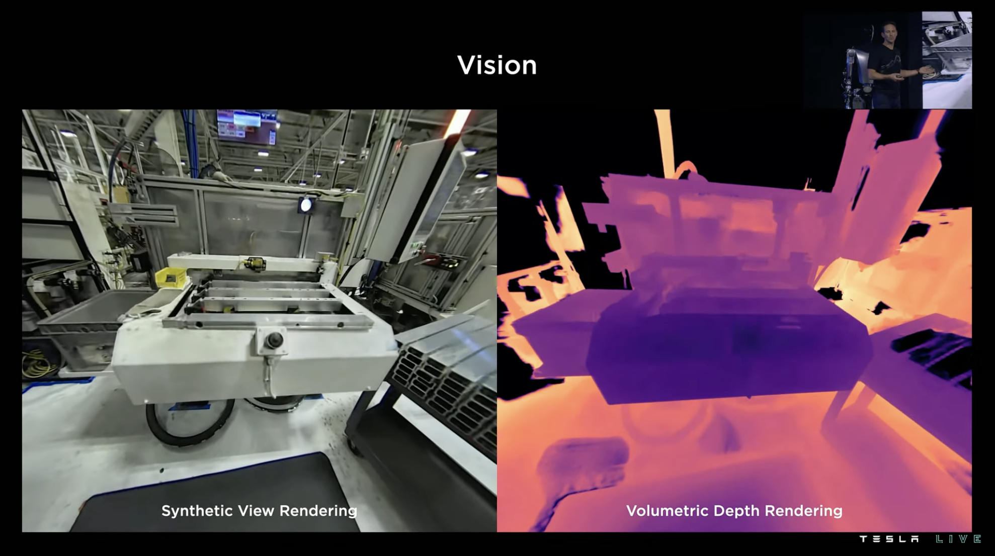
For robots, achieving autonomous indoor navigation with only GPS signals as support is another challenge, after all, indoors do not have lane lines or signs.
To achieve this, Tesla has adopted a special path navigation method for robots, building a spatial point cloud map by using objects detected through vision, training the robot to recognize common objects and key features in indoor environments, and then avoiding entities in the environment to plan feasible paths in the map.
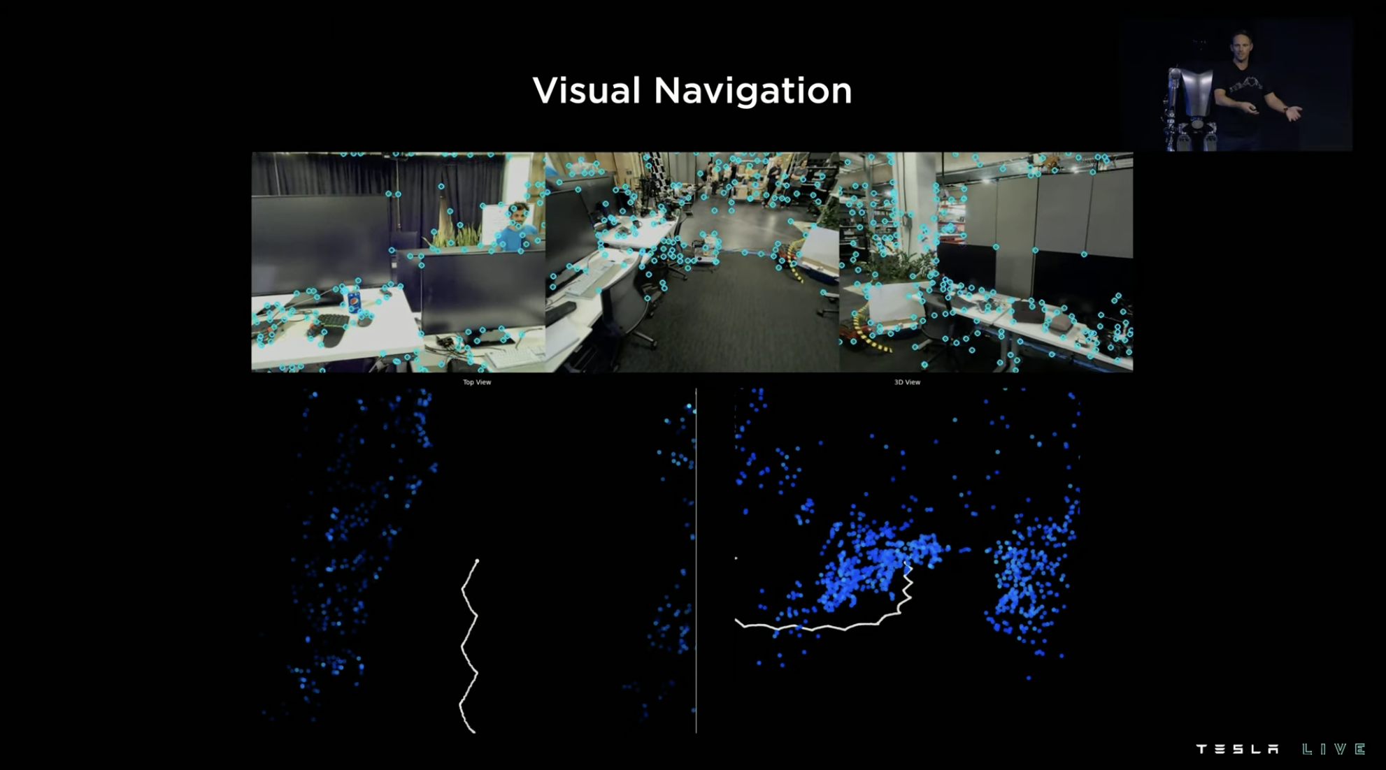
Tesla has its own simulator for simulating road environments in FSD training, and has prepared a similar simulator for training Optimus. The following figure shows the kinematic demonstration of the robot at different stages with different joint motions in the simulator.

Walking is actually not easy at all
“Walk seems pretty easy, doesn’t it? We walk every day, controlling it purely based on feeling, and we don’t even need to think about it.” When a Tesla roboticist starts talking like this, it usually means that this seemingly simple task is actually very complex. The scientist then said in engineering terms, there are four major challenges to make robots walk.
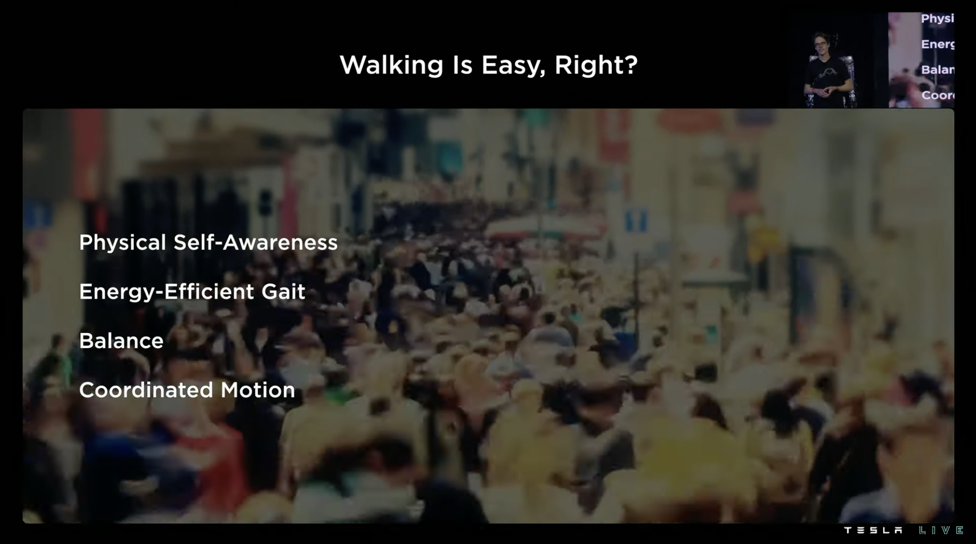
First, humanoid robots need to have physical self-perception, knowing how long their strides are, how heavy their legs are, and where their feet will land;
Second, humanoid robots’ walking movements also require good high-energy-efficiency bandwidth to ensure good energy efficiency under different walking conditions.Thirdly, it is very important to have sufficient self-balancing ability to ensure walking without stumbling.
Fourthly, there is a need for spatial coordinate positioning ability during walking, or the ability to convert spatial coordinates into precise walking positions. The software stack that solves these problems is called the “Locomotion planning and control stack”. It involves the dynamics, kinematics, and limb contact control of robots.
A planned path is broken down into finer control instructions after being input into the system, which can be divided into three stages.
At first, the “footprints” of each step are planned according to the walking route, and this information is broken down into corresponding lifting and heel landing actions under the corresponding path in the “Locomotion Planner” in the second stage. These actions link every step and allow robots to take larger strides with less knee flexion, thereby reducing the energy consumption of walking actions.
Finally, the system calculates the trajectory of dynamic balance motion that the robot can maintain under the corresponding action. Therefore, the planned path to action breakdown and planning are completed, and the next step is how to get the robot to execute it.
Although we have discussed a lot about Optimus’ motion planning strategy, the reality is that the execution of robots in the real world may deviate from the plan, and robots may keep falling down.
The explanation for this phenomenon is straightforward: the simulated robots and environment in the software are ideal, while the environment in the real world is much more complex. For example, the robot itself will have slight vibrations, and the sensor will be interfered by noise and so on. Interference outside the motion planning and control stack calculation will cause deviations during execution. For bilateral walking actions that belong to dynamic balance, such interference leads to instability.
The solution is to break the “closed-door mentality”, incorporate real-time environmental perception feedback into the robot’s stability detection system, and output the correction signal obtained by the stability system through environmental detection to the motion control system, thereby forming closed-loop control integrated with real-time status perception to maintain dynamic balance of the robot. This approach sounds a bit like a robot version of “lane centering assist.”
How to Help Robots “Practice”
After maintaining basic walking balance, Optimus’s next goal is to “use both hands.” This is a key step that transforms Optimus from a traditional humanoid robot into a valuable workforce (a machine worker).
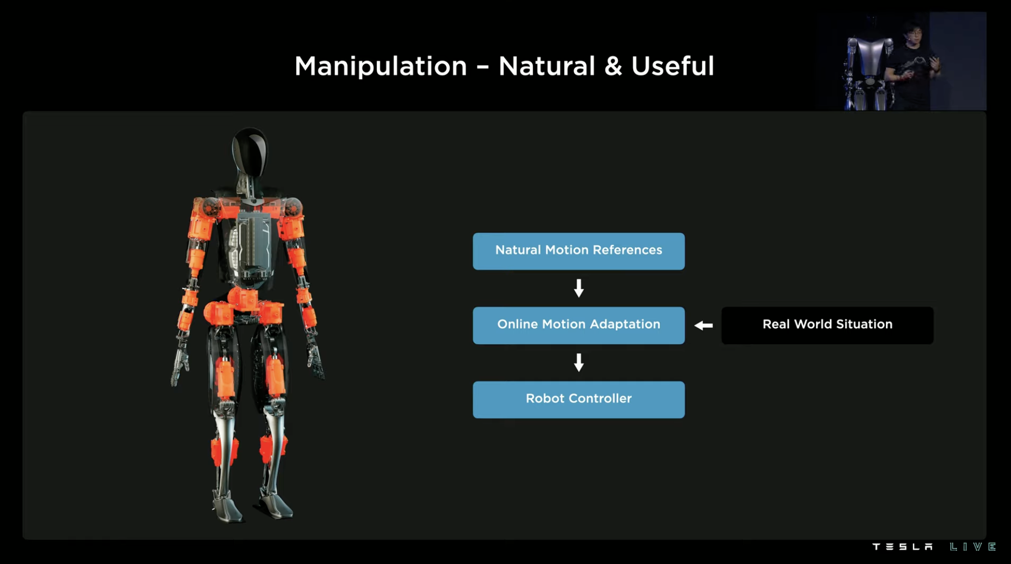
The process of training hand movements can be understood as “real-life operation guiding the way, system learning to regenerate.” First, use motion capture to obtain the kinematic information of human hands in a certain action, and then reverse the collected motion information to generate simulated movements of the robot. When enough human demonstration actions are collected, a database of this set of movements can be formed.
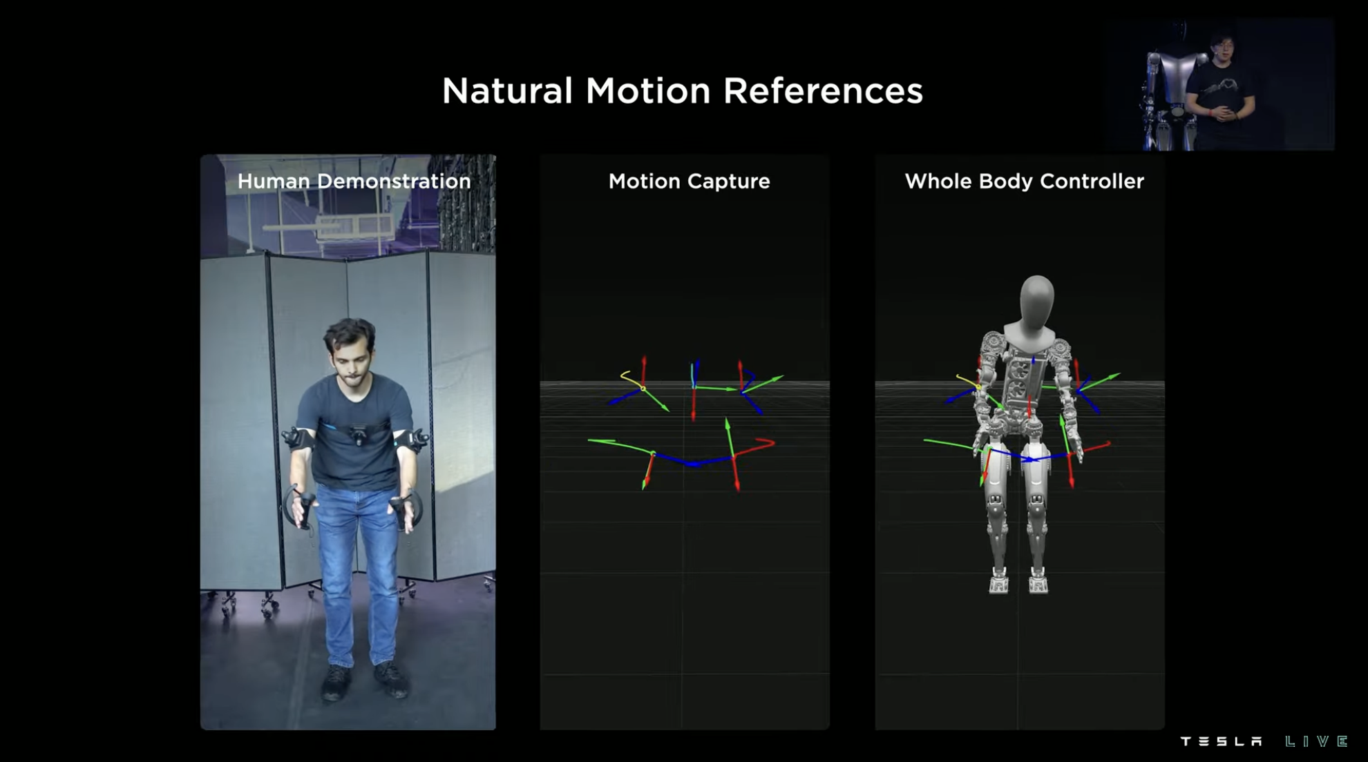
However, in real life, the same type of action will have many different execution details. For example, when lifting a box, the size and position of the box will change. If the human demonstration only demonstrates lifting a box straight ahead, then the reverse learning robot can only learn how to lift a box straight ahead.
This efficiency is obviously very low. In order to achieve one-to-many transfer, Tesla has also added a set of online motion trajectory optimization and control systems. This system adds adaptive adjustments for the real environment on top of the basic learned movements, re-calculating how to place hands and how to achieve balance in new movements in different scenarios, thereby increasing the range of applicability of the learned movements in real situations.
Summary 1: Expectations and Value of Optimus
The content about Optimus in the first section mainly covers Tesla’s thoughts on the design of this robot and the training strategies that make it more powerful. Compared to various technical details, the core concept of this robot is very clear: it should be cheap, mass-producible, and able to work like humans.If these three goals can be achieved to a certain degree, it will be a remarkable achievement. Because humanoid robots like this will have the potential to replace some of the social labor force. The selling price may eventually be less than $20,000, and the energy consumption cost in subsequent production work can be almost negligible compared to the value it can generate, excluding the purchase cost.
One can imagine that if a machine worker that can work almost 24 hours a day only costs a few degrees of electricity in daily wage, even if its efficiency is not as good as human workers, it still has a high input-output ratio. Even for jobs like guarding, Optimus, with its ability to monitor three routes without fatigue and real-time networking, is a perfect solution.
I even thought, based on pure visual perception, if Optimus shares neural network algorithms with FSD, is it possible to achieve another form of “unmanned driving” in the form of a robot driver?
In short, if Optimus’s goal is to “become human,” the imagination of this business will be immense.
However, to come back, many of the introductions about Optimus in the press conference are still in the “expected” stage, to be harsh, it can be said to be the PPT stage. But as a new business line of Tesla, Optimus has been very efficient from its announcement last year to the production of prototypes this year. Tesla will strive to mass-produce it within three years.
FSD Beta: Two-Year-Old “Experienced Driver”
The focus of the 2021 AI Day was FSD, and FSD appeared in the second part this year. First, Tesla showed the changes experienced by FSD Beta users between 2,000 people and 160,000 people in one year:
-
A total of 35 software updates were pushed;
-
281 neural network models that can improve FSD performance have been launched;
-
During this period, there were 18,659 code improvements;
-
A total of 75,778 neural network models were trained by machine learning (an average of one new model added every 8 minutes);
-
There are 4.8 million datasets.
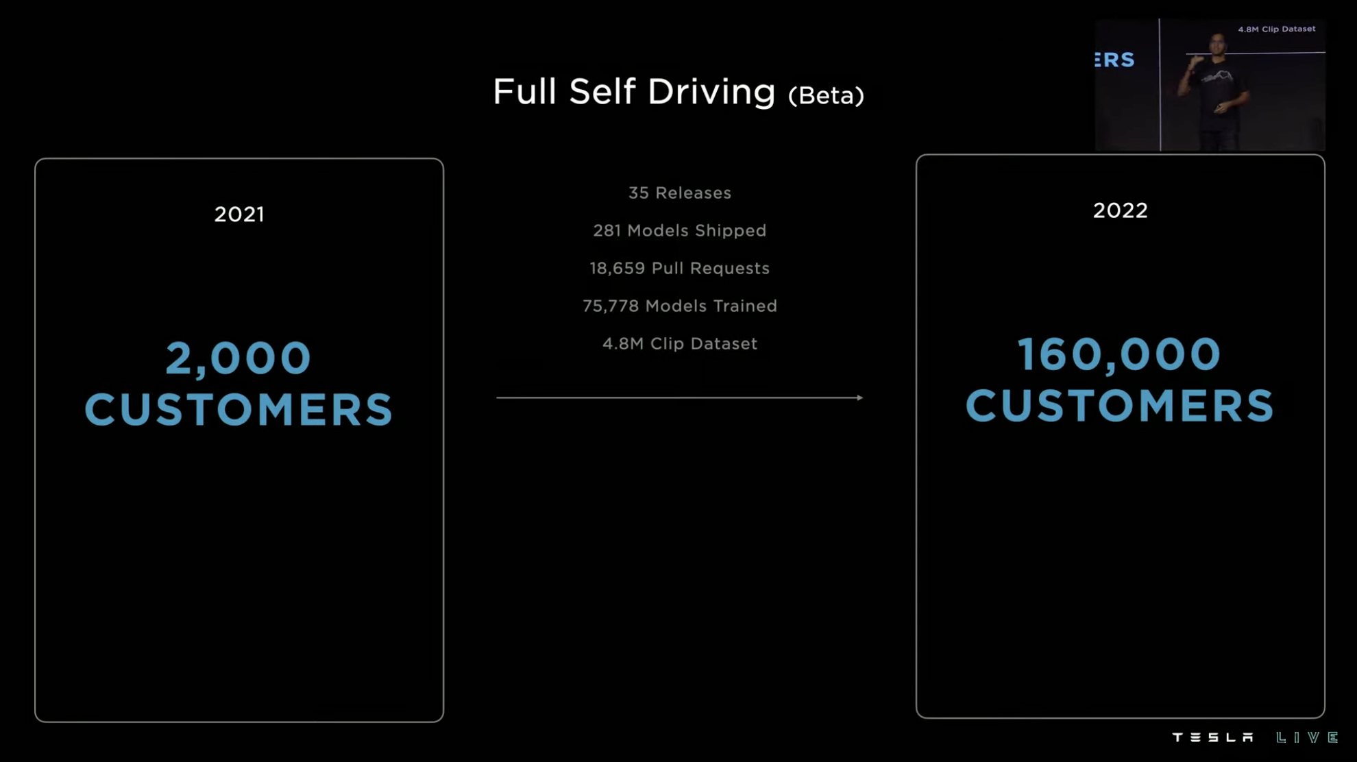 If FSD develops as planned, it is still a system based on single-vehicle intelligence and pure visual perception. It has 3D environment perception based on visual neural networks and low-latency local control capabilities. Today’s FSD Beta can achieve point-to-point intelligent driving from A to B. The task of FSD team is to make FSD can support more and more broad scenarios from A to B, while making the process from A to B smoother.
Tesla FSD now consists of five parts. The top part is the vehicle’s control system, below which is the perception neural network, which includes detection of the real world environment and recognition and understanding of driving roads. Below the neural network is the training data of machine learning. Tesla’s training data comes from automatic labeling, training-specific simulators, and feedback data engines driven by shadow mode.
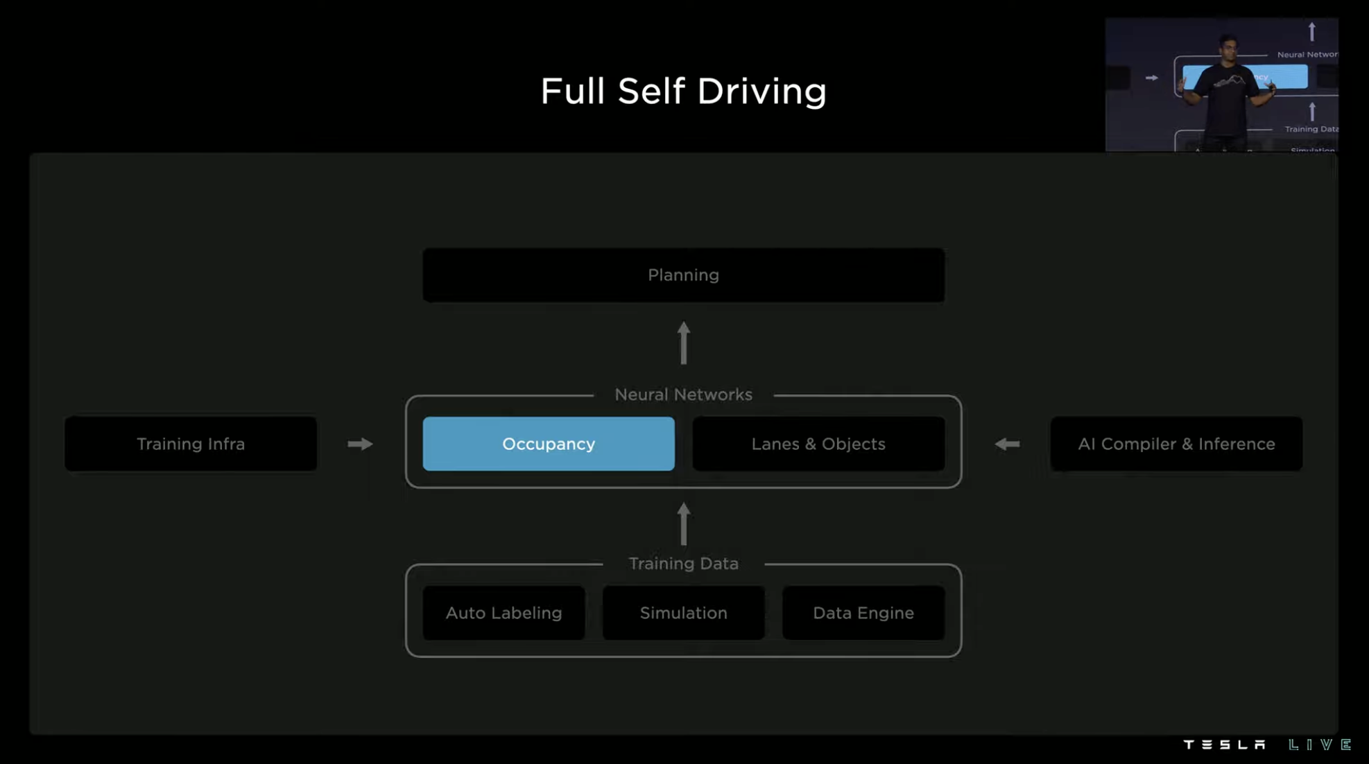
Training of software algorithms also needs the support of systematic capabilities, which is the “Training Infrastructure” on the left side of the perception neural network. Tesla’s Dojo supercomputer system is the core hardware of this system in the future.
The auxiliary part on the right side of the figure is the AI compiler and inference engine, which is mainly used to run the same neural network on two independent SoCs using HW3.0 computing chips. The system must be able to support such operations with low latency through various improvements.
Next, let’s take a look at the current level of FSD Beta from the path planning.
Driving Decision: Comprehensive, Safe, and Long-term
The demonstration in this part starts with an unprotected left-turn case at an intersection. The three red circles marked in the figure are the three traffic participants that the system needs to closely monitor in the execution of this left turn. On the left is a pedestrian crossing the road with a dog, in front is a vehicle turning right at the approaching intersection, and on the right is a normal vehicle driving straight. Predicting the trajectory of these participants determines the timing, speed, object spacing, and route for the vehicle to enter the intersection.

In the vehicle’s path planning and control system, several predictions have been made for this scenario.The first strategy is aggressive driving, directly entering the intersection quickly before pedestrians and turning left into the straight lane. At this time, the two light blue vehicles will not interfere with our driving, but this strategy obviously poses a certain danger to pedestrians walking their dogs.
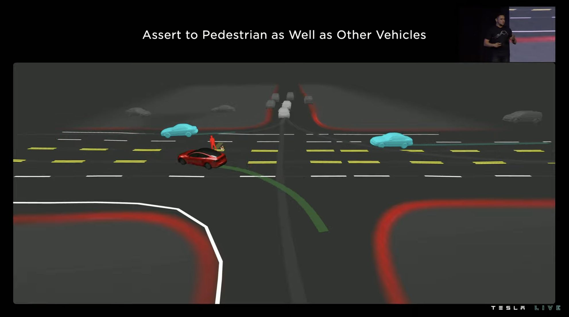
The second strategy is to give priority to pedestrians over vehicles. Vehicles enter the intersection slightly slower than in the first strategy, and immediately turn left into the straight lane after the pedestrians have walked past the double yellow line. However, this approach will force the vehicles going straight on the right to significantly reduce their speed, which does not follow the logic of “turn left after straight” at intersections.
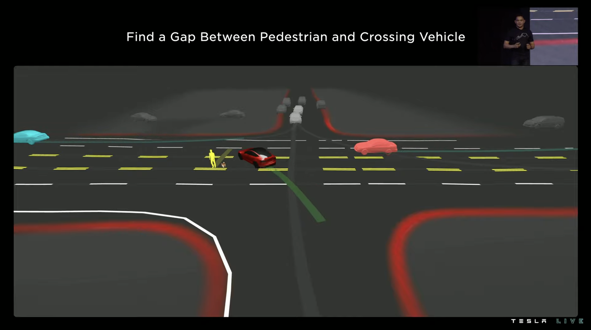
The third strategy is the actual choice of vehicles. After waiting for pedestrians to pass the double yellow line, and for the vehicles going straight on the right to pass, vehicles enter the intersection. At this point, the vehicle is no longer interfering with the traffic participants at the intersection.

Expanding the decision-making process of the system in this case, it involves predicting and calculating every possible parameter. For example, regarding the vehicle going straight on the right, what is his minimum deceleration rate to avoid collision with us during different insertion times?
However, this is just the tip of the iceberg. If the goal is to only avoid collision with the vehicle on the right, then the decision-making level of the entire system will not be very high, because in real road environments, there are far more participants to consider than this.
Therefore, the problem ultimately becomes how the control system completes path prediction for multiple traffic participants while considering how their own routes impact them.
The maximum number of traffic participants that can be simultaneously calculated in the planning phase determines the speed of vehicle decision-making. The upper limit of this process is approximately 10 ms (0.01 seconds).
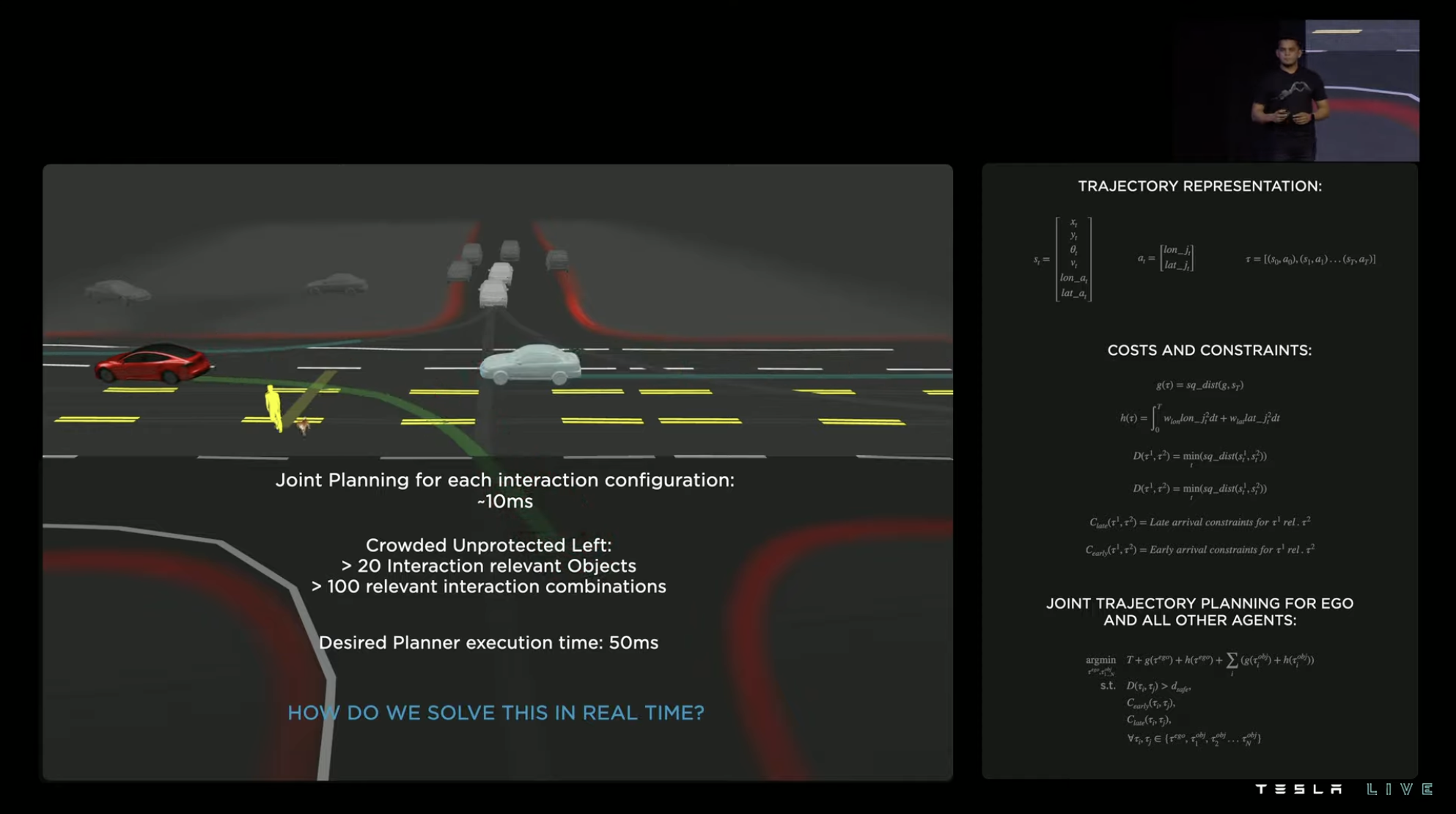 For an unprotected left turn, there are typically more than 20 traffic participants to be considered in the path planning. The system generates over 100 combinations of their trajectory. This calculation puts a heavy burden on the system. If we use the previous calculation method, it could take the system over 1,000 ms to make a decision. However, Tesla requires the control system to make final decisions within 50 ms.
To solve this problem, the FSD software team has added a best path search mechanism to the algorithm of path planning. The logic is to give priority to the most feasible solution, rather than simply divide resources evenly.
The factors to be considered include the vehicle’s own trajectory, the road environment structure, the trajectory of other traffic participants, the actual lane markings, traffic lights, and regulations. In the selected candidate route, the system also considers intersection decisions and future long-term path selection maneuverability.

After two levels of reasoning through the parallel tree, the system generates multiple feasible driving routes. Starting from the third level, the factors considered by the system to choose among feasible routes gradually increase according to priority from high to low.
For example, several types of routes at unprotected left-turn intersections are generated at this level, while the aggressive driving route that threatens pedestrians on the left is rejected in this step.

Moving on to the fourth level, the system continues to add more constraints, such as the example in the previous case that requires reducing the speed of the vehicles that continue to drive straight after the left turn.

Based on the numerical optimization of the physical model, it takes 1 to 5 ms to generate each result. As mentioned earlier, in the case of unprotected left turns, the number of route combinations that need to be predicted may exceed 100, so the accumulated delay is still significant.
 Tesla came up with another solution, directly enabling the system to “look up words in the dictionary” – by adding a lightweight searchable network in the regulatory network loop, which includes templates actually demonstrated by human drivers in the Tesla FSD queue (enrolled FSD vehicles), as well as solutions trained by offline solvers with ample time limits. The strategies suitable for this scheme only need 100 us (0.1 ms) to generate once.

The two path generation strategies are combined and the system continues to score and rate the planned path, which includes collision checking and route comfort evaluation. The system also tests the driving routes demonstrated by humans in the FSD queue and scores the outcomes of the next few seconds at the corresponding intersections. Another set of scores is based purely on how similar the system’s regulatory strategies are to humans’.
Therefore, this major step includes both the absolute rationality of physical model numerical screening and the relative sensitivity and human logic-oriented anthropomorphic logic level consideration, reducing the number of required generated paths based on scoring and reducing the system decision-making process’s delay.

Prerequisite for good decisions: Accurate and Rich Perception
At the beginning of the introduction of the 3D environment perception network, Tesla presented a very common case of camera occlusion. The purple vehicle in the upper-left corner of the figure will be occluded for some time during the process of the red-circle vehicle turning left. If no other measures are taken, there will be gaps in the road object perception during this occlusion period.


However, if the predicted trajectory during the occlusion period is generated by reasoning through the traveling trajectory before the object was occluded, the loss of perception information during the occlusion period can be reduced, enabling the system to make better decisions. This case also demonstrates the importance of perception for regulation.The perception neural network running in Tesla’s FSD software can use image information captured by 8 ADAS cameras to generate a sense of stereoscopic perception of the driving environment, enabling volume perception of various objects in the road environment. In addition to stereoscopic detection, it can also identify semantic information of different objects, such as cars, roadblocks, road signs, pedestrians, shoulders, and even road gradients.

The information flow of the road environment perceived by the system is also used for dynamic trajectory prediction of various features. In the example shown, a pickup truck’s trailer exhibited sway when passing over an arched bridge. The system predicted the trailer’s tendency to swing left in the next stage when it swung right, so it avoided to the left in time.
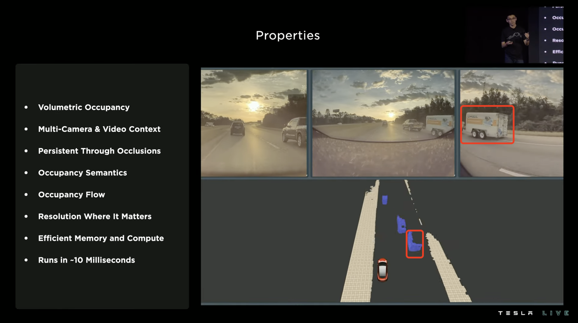

This dynamic trajectory prediction system updates data every 10ms and is applied to all vehicles with FSD chips (HW3.0).
Advanced Vision: From Raw Materials to Usable Data
Tesla’s research on visual perception has permeated every aspect.
The initial step is camera information calibration. In this process, the system “raw processes” the image information obtained by the 8 ADAS cameras, performing distortion correction processing, and then inputs it into the feature extraction layer of the next step.
It’s worth noting that in this “raw processing” process, the image information obtained by the camera does not go through the ISP (Image Signal Processor), but instead the 12-bit color depth photon information is fed directly to the feature extraction layer. This reduces the latency caused by the information passing through the ISP, and obtains a color dynamic range 16 times greater than 8-bit color depth (the ratio of the maximum signal to the minimum signal is 16 times greater).
 After the feature recognition and detection is completed by the image feature extractor, the system constructs a queryable 3D spatial model using these materials, and then runs the key features and parameters in the “key space” model.
These contents are output as high-dimensional spatial features after being processed by the “key space”. Then, the system associates these high-dimensional spatial features with their coordinate information at different time points to complete temporal alignment of features.
Finally, the system performs reverse calculation of the aligned temporal and spatial high-dimensional features to generate volume estimation results of the features in the space, which are displayed as gray blocks in the model.
For features that require higher accuracy, the system also further refines and restores the above “gray solid block” by putting it into the MLP multi-layer perception operation model, and uses queryable 3D point cloud data to obtain the semantics and coordinates of features at any position.
Tesla then presented a hinge-type coach feature recognition case. In the figure, there is a parked hinge coach on the right side of the road, which is identified as a static feature (marked in red) by the system.
As the vehicle approaches, the front half of the articulated coach starts moving, but the back half of the coach remains stationary. At this time, the perception system has already started to react, identifying the front half of the coach as a dynamic feature (marked in blue), while the rear half of the coach is still recognized as a static feature.
When the hinge coach continues to move forward, the system further recognizes that the rear half of the coach and the front half of the coach are a moving unit, so the whole hinge coach is identified as a coherent dynamic feature, and the bending contour of the coach side and angle between the front and rear coaches are accurately restored.
For traditional feature recognition, the difficulty of this case lies in whether the system will recognize the hinge coach as two features or one feature, which determines whether the system will use a single or two biggest bounding boxes for volume estimation of the hinge coach during computations, because the hinge coach is curved when turning, and this deviation can cause the system to misjudge the interference volume of the hinge coach.Tesla’s visual perception system accurately constructs the feature space state of the scene. In addition to identifying traffic participants, the system can recognize the “drivable space” on the road. This capability can help the system better control the car in construction zones and curves. The results of road 3D perception are expressed not by volume blocks, but by generating relatively smooth and continuous simulated surfaces based on environmental information.

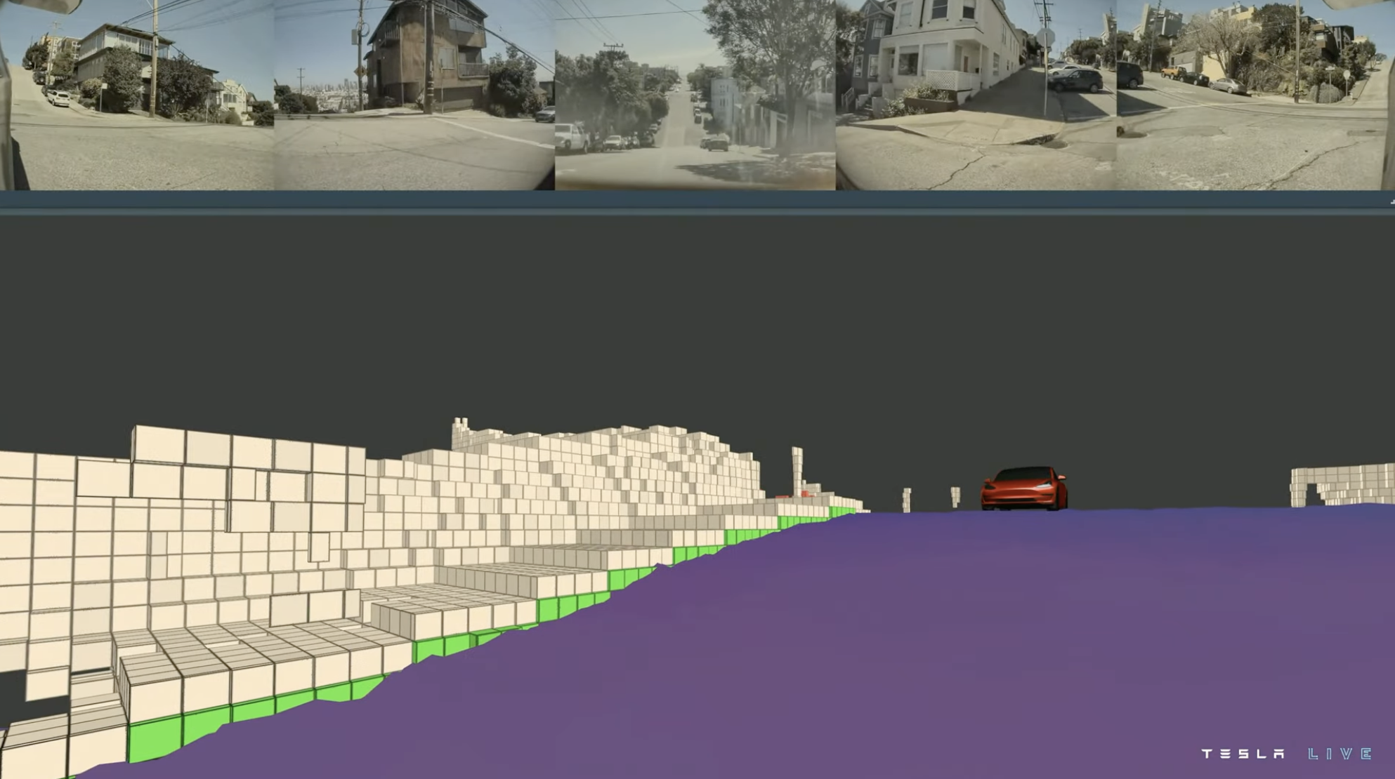
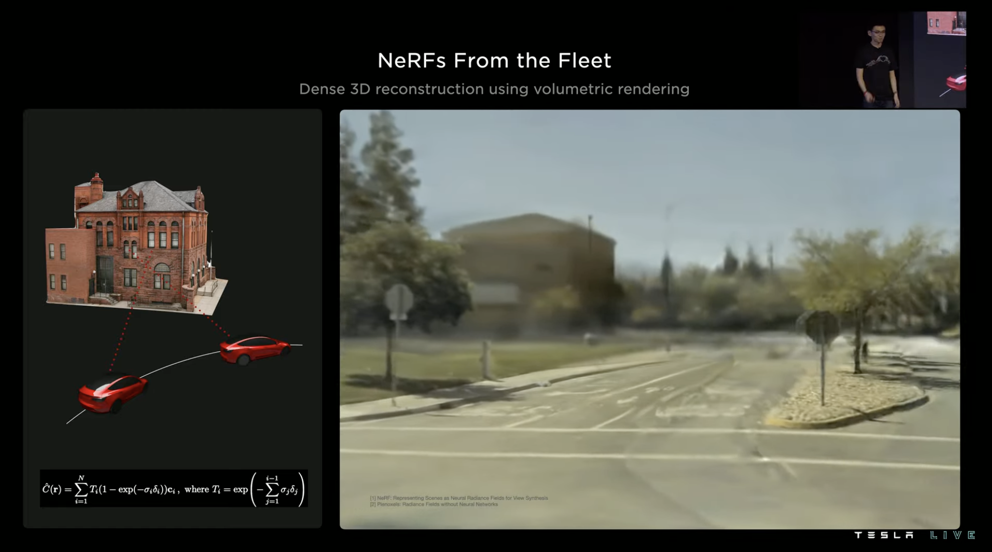
In the final section of this article, Tesla also introduced their recent breakthrough in NeRF, the Neutral Radiance Field neural network. Tesla is trying to use this model to achieve a more powerful vision-based 3D environment model.
In other words, Tesla hopes to use this method to globally achieve high-resolution, high-fidelity stereoscopic environment information collection for FSD fleets.

When talking about NeRF, Tesla presented a high-precision 3D environment reconstruction scene created using FSD fleet’s collected volume rendering information. The current result has achieved remarkable fidelity.
Returning to Tesla’s visual perception network, the entire neural network’s feature perception ability is achieved through massive automatic labeled data training. Tesla’s ultimate goal is to eliminate any manual intervention in the closed-loop data training process. Next is the introduction of Tesla’s automatic labeling process.
Data training software optimization: reducing internal friction## Machine Learning Training: A Critical Component of FSD Structure
Machine learning training is a critical component of the Full Self-Driving (FSD) structure and also a time-consuming process due to massive amounts of data. According to Tesla’s statistics, the several video clips used for high-level visual demonstrations were the results of 1.4 billion frames of training material.
If we assume that the GPUs used for training work at a performance state of 90℃, then 100,000 GPUs working for one hour can complete the aforementioned training. Conversely, if a single GPU is used, it would require 100,000 hours (136.9 months) to achieve the same level of training.
However, such a workload is unrealistic to be completed manually.

Tesla’s current cloud computing training network has 14,000 GPUs, of which 10,000 are used for training and the remaining 4,000 are used for automatic annotation.
The training videos are stored as distributed 30 PB (30,720 TB) video cache and up to 500,000 videos input into the training system every day. The training system can simultaneously process up to 400,000 Python video instances every second.
To handle such a massive training task, Tesla has developed a proprietary software system.

In a training system, the accelerator (NVIDIA A100 GPU or subsequent Dojo) is the most expensive hardware and should be the bottleneck of system performance since it represents the highest usage of the system.
Alternatively, all other system components should process tasks at a volume higher than the accelerator to avoid overperformance and over-cost.
Various funnel-like performance considerations need to be taken into account, including memory capacity, storage transmission bandwidth, node CPU performance, node memory capacity, and more. Tesla has optimized and improved mechanisms to ensure that the system’s performance is not limited by the accelerator.
Videos used for training are more complex than images; therefore, Tesla begins with optimization from the upstream storage until the final accelerator to optimize the nodes for efficient training.
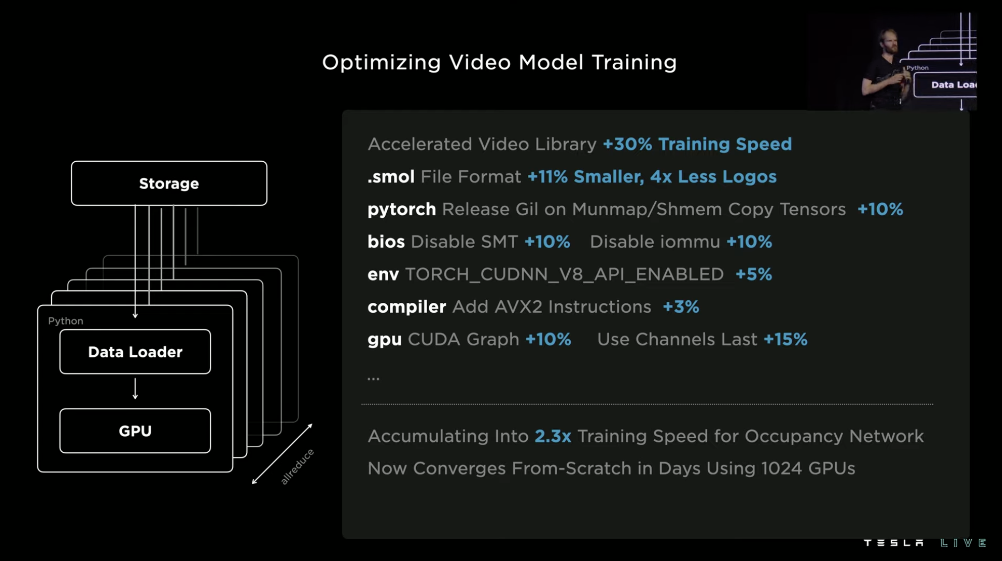
 The video material itself is not processed in any way during transmission. Tesla only selects the required training frames and key frames from it, and then packages it for transmission to shared memory, then to the GPU. Afterwards, the video material is decoded by a hardware decoder accelerated by the GPU. Therefore, this is equivalent to using the GPU directly for this task, without occupying other computing hardware resources, and the system’s training speed can be increased by 30\%.
This is the measure that yields the most efficiency improvement, with the other measures contributing up to 15\%, or at least 3\%. After being layered on top of each other, the training speed of the environment perception network has been improved by a factor of 2.3.
Junction Challenge: The Need for a Map
In lane recognition, the commonly used method is 2D pixel recognition, which inputs image information and distinguishes between the current lane line and other routes. This method works well on well-paved roads with relatively simple situations, such as highways.
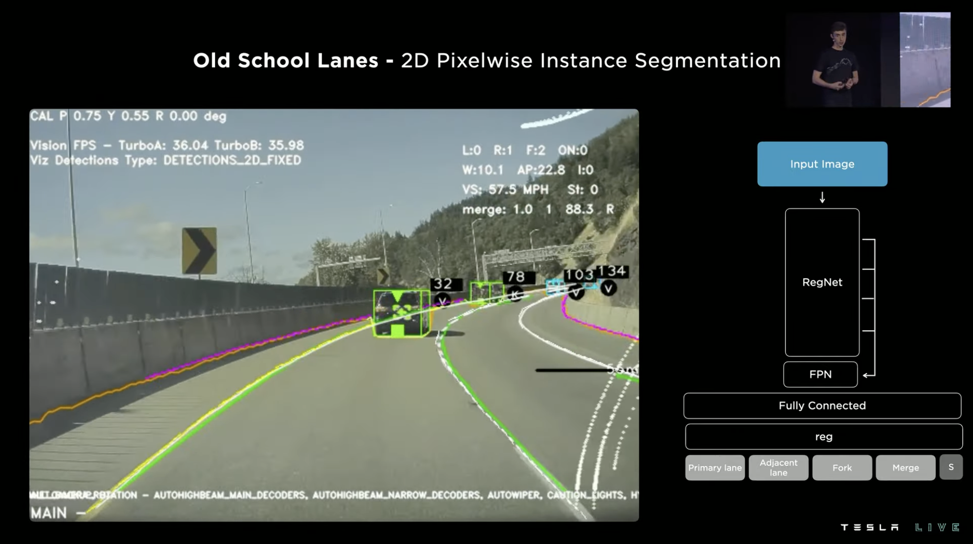
However, if the same method is applied to the relatively complex city-level intelligent driving, especially difficult junction scenes, the lane prediction results obtained by 2D pixel recognition are completely different. The recognition results obtained by the system are almost unusable. As described in the original text, a simple turn could “break structured lanes,” and the results of complex junctions are “hopelessly insufficient.”

The image on the left is the information Tesla hopes the system can obtain, the roadmap of the entire junction. Each location where the road merges, forks, or stops is called a node.
As you can see, the lines between different nodes are not simple straight lines or arcs, but are affected by the actual road shape and lane geometry. Therefore, the system needs to combine these factors to calculate the lines between nodes.Tesla has recently introduced a new system called “Lane detection neural network” as an alternative approach because the original method was proving to be ineffective. The system consists of three main components.
The first component is the visual perception module, which is similar to the visual network of the original FSD. The system can use visual perception to generate a rich video model of the road environment.
In the second module, this information is processed together with the vehicle’s navigation map information in a module called the “Lane guidance module”. The map used here is not a high-precision map, but it provides a lot of basic guidance information for calculations. The output of the module is a dense tensor, which is equivalent to “information decoding” at intersections.
These dense tensors are then inputted into the third module, where Tesla aims to transform the output into a lane map. The process is similar to generating subtitles from images. The dense tensors generated in the second module are fed into the semantic regression decoder to generate a kind of text that can be used to infer lane relationships. Tesla defines this text as a special “route statement”.
The “words” and “markers” in this statement are the lane coordinates in the 3D world, and the modifier tool in the markers can decode the relationship between lanes. Therefore, the final output of the lane map will look like the image below.
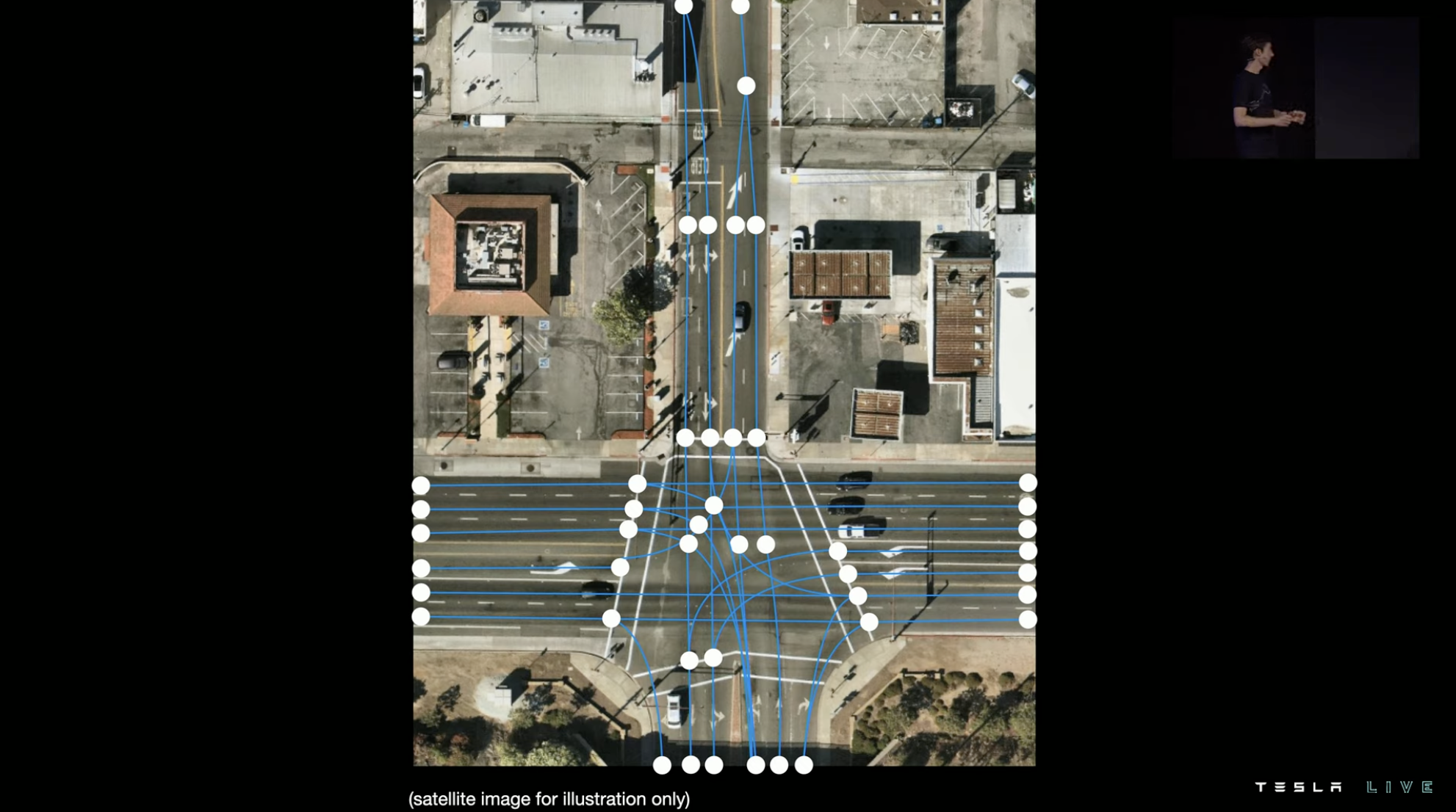
In essence, the process involves first identifying the areas where the road is located on the map, then marking the nodes on the road (such as the starting point, stop line, intersection, etc.), connecting the lines between the nodes, and then matching and optimizing the connected lines based on the actual geometry of the road.
In terms of specific details, Tesla uses the satellite view of the intersection as a blank canvas and marks a green dot at the starting point of a lane to encode it as the starting point index of the grid segmentation map of the intersection.
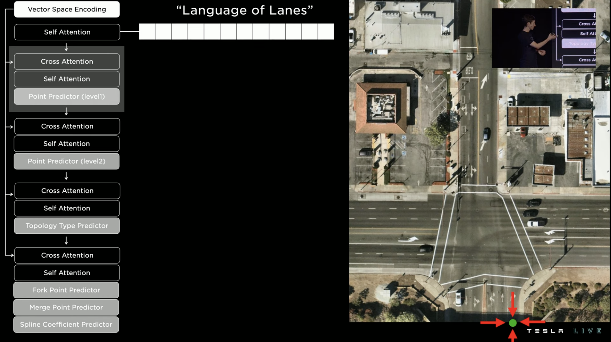
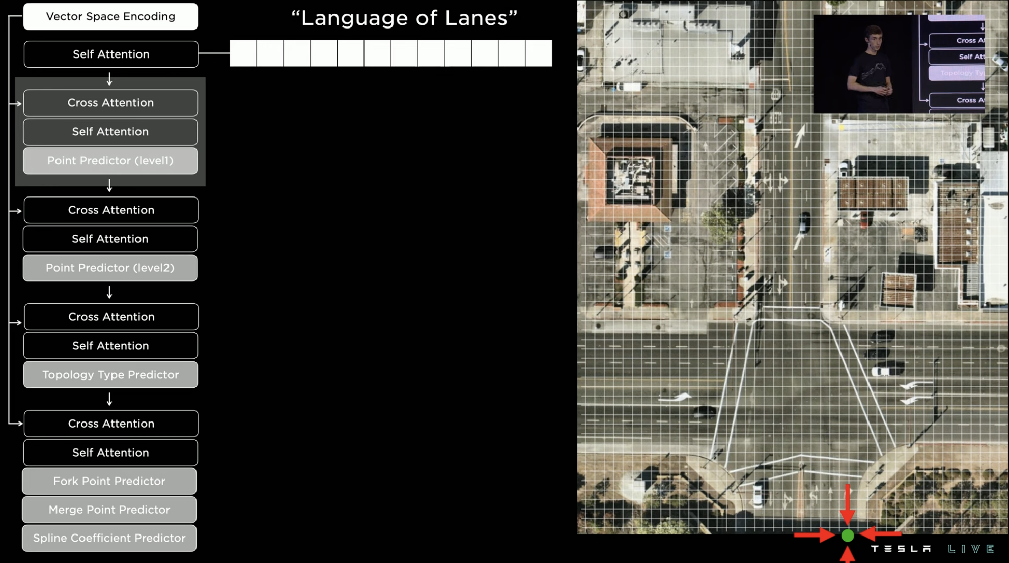
Since there are many grid points in the image, predicting the entire image directly consumes too much computing resources. If better prediction strategies are developed for this type of problem, they will improve the training and testing processes simultaneously.The first step in reducing computing consumption is to decrease the index density. Then, based on the vehicular flow heat maps of roads, the possible road regions are roughly located (the lower the opacity, the greater the vehicular flow). Within these heat maps, the grid area with the highest probability is selected for further precise positioning and prediction, in order to find the exact nodes.
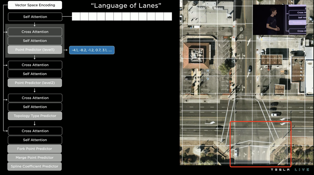
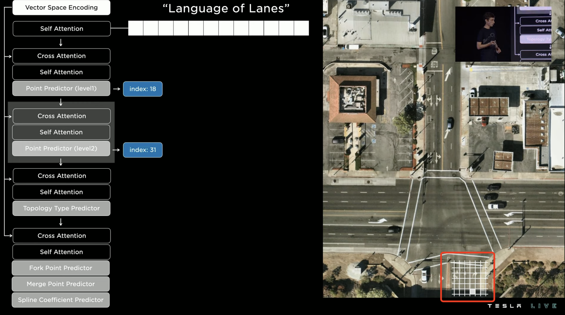
There are different types of nodes, and the one found here is the starting point of a route, so it is marked as a green “starting node.” Therefore, the first word of the “route statement” is generated.

Continuing the previous step to find the next node, this time the stop line at the intersection for a right turn is found. Because this node is on the extension of the green line, it is marked as an “extension node.”
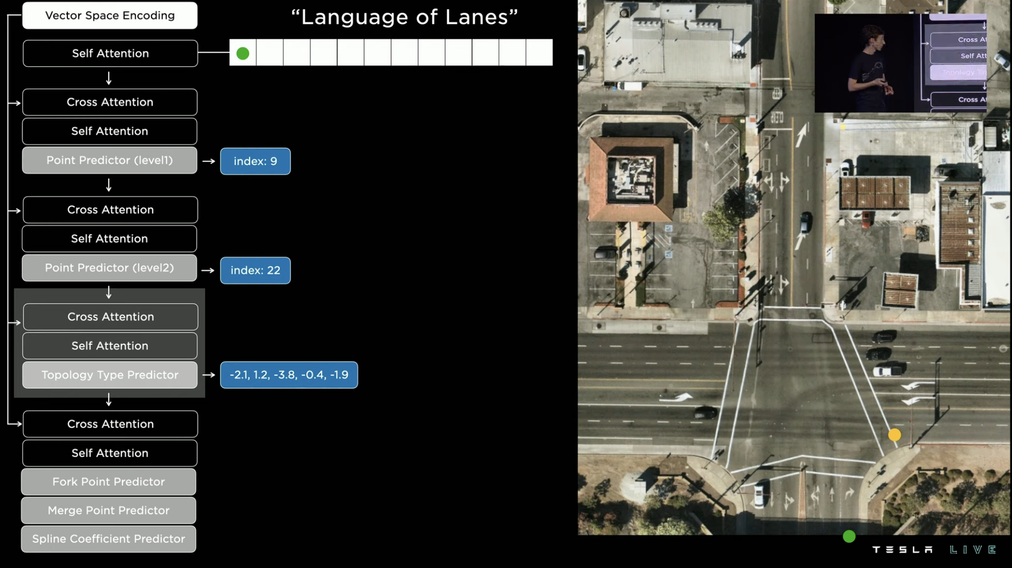
Two nodes need to be connected by a route, with the most basic method being a straight line connection. However, the geometric shape of the intersection needs to be taken into account here, so the system will turn the route into a suitable driving curve for a right turn, and the second word of the “route statement” is generated.
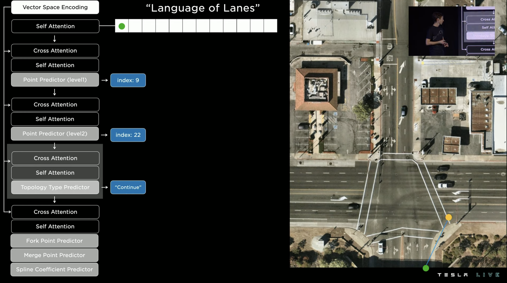
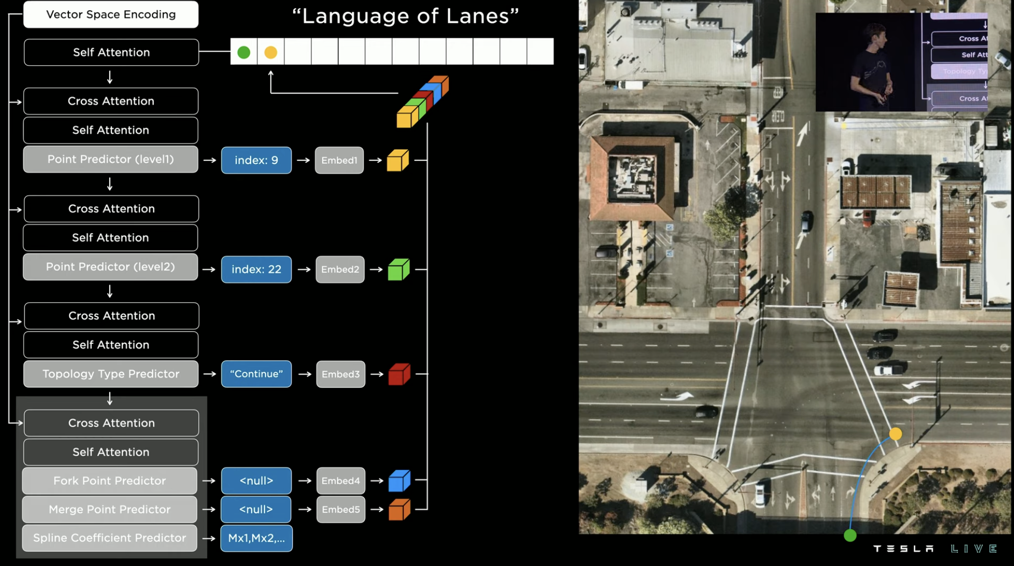 Continuing along the previous route, the right turn route on the map ends and is marked by a magenta dot. Returning to the green starting point, one can continue indexing and discover that turning right not only leads to the first lane on the right, but also the second. The green node leading into the second right lane is called a branching node. Following the branch node, the next node is the end of this branch.

After repeatedly executing the above indexing process, the entire intersection’s road map is completed.
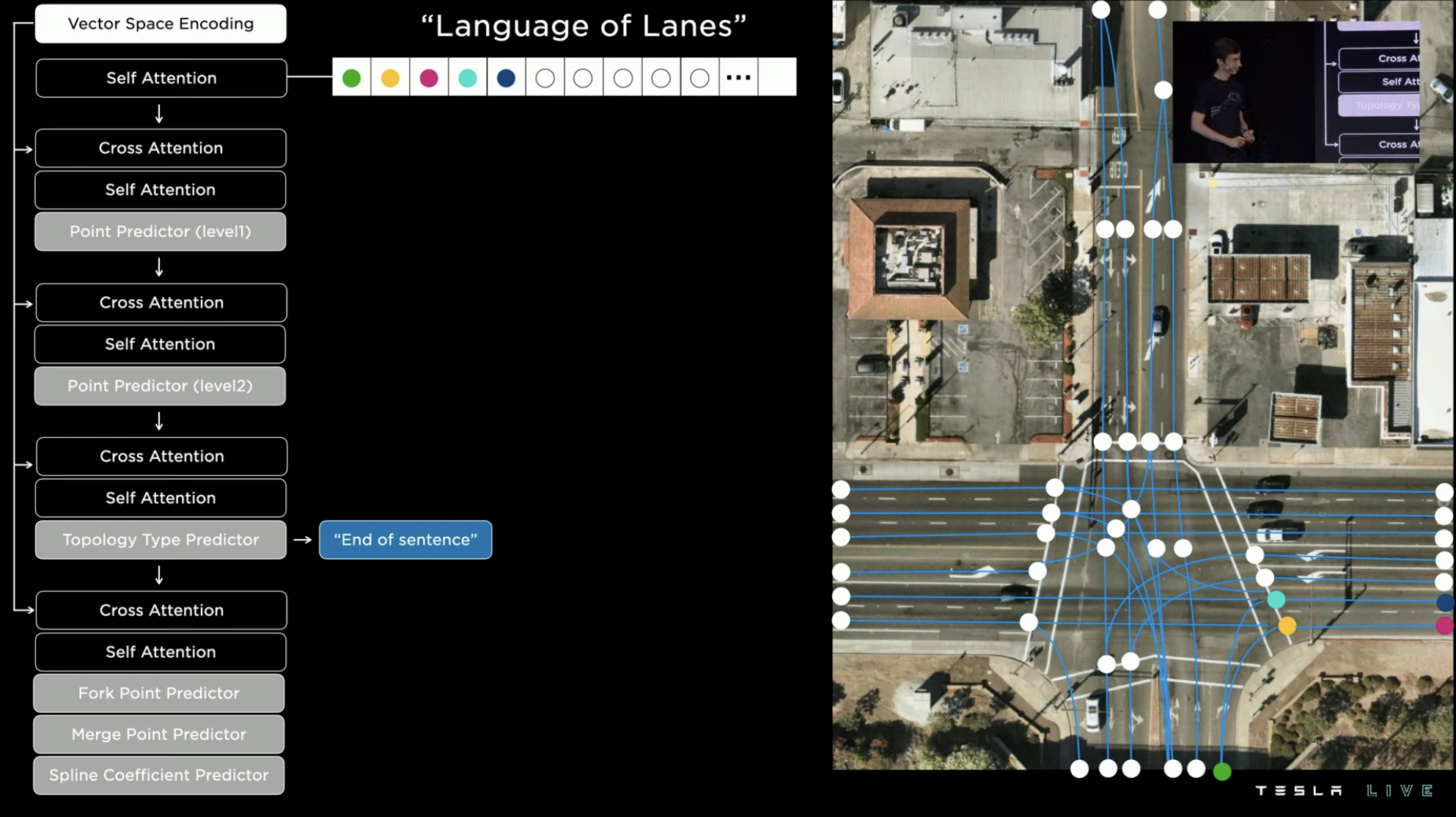
At first glance, the prediction method for intersection roadways seems rather complex, but in reality, the FSD team tried other “simpler” methods, such as using lane division to predict routes. However, in reality, lane markers are often unclear or obscured by inclement weather, making the system unable to determine the precise number of lanes. Thus, the system often fails.
There are many limitations to similar schemes, such as the inability to handle overlapping routes. To resolve this problem, the route may need to be processed on multiple layers. In summary, these schemes are complex and inefficient.
On the other hand, the framework model of “route statements” can more easily extract samples, making it suitable for later perception processing. This framework will not only be used for FSD, but will also be used for Optimus’ perception system.
The final effect is shown in the following figure. The vehicle’s own system can directly generate the intersection’s driving route map without other external aids (such as preloading high-precision maps).
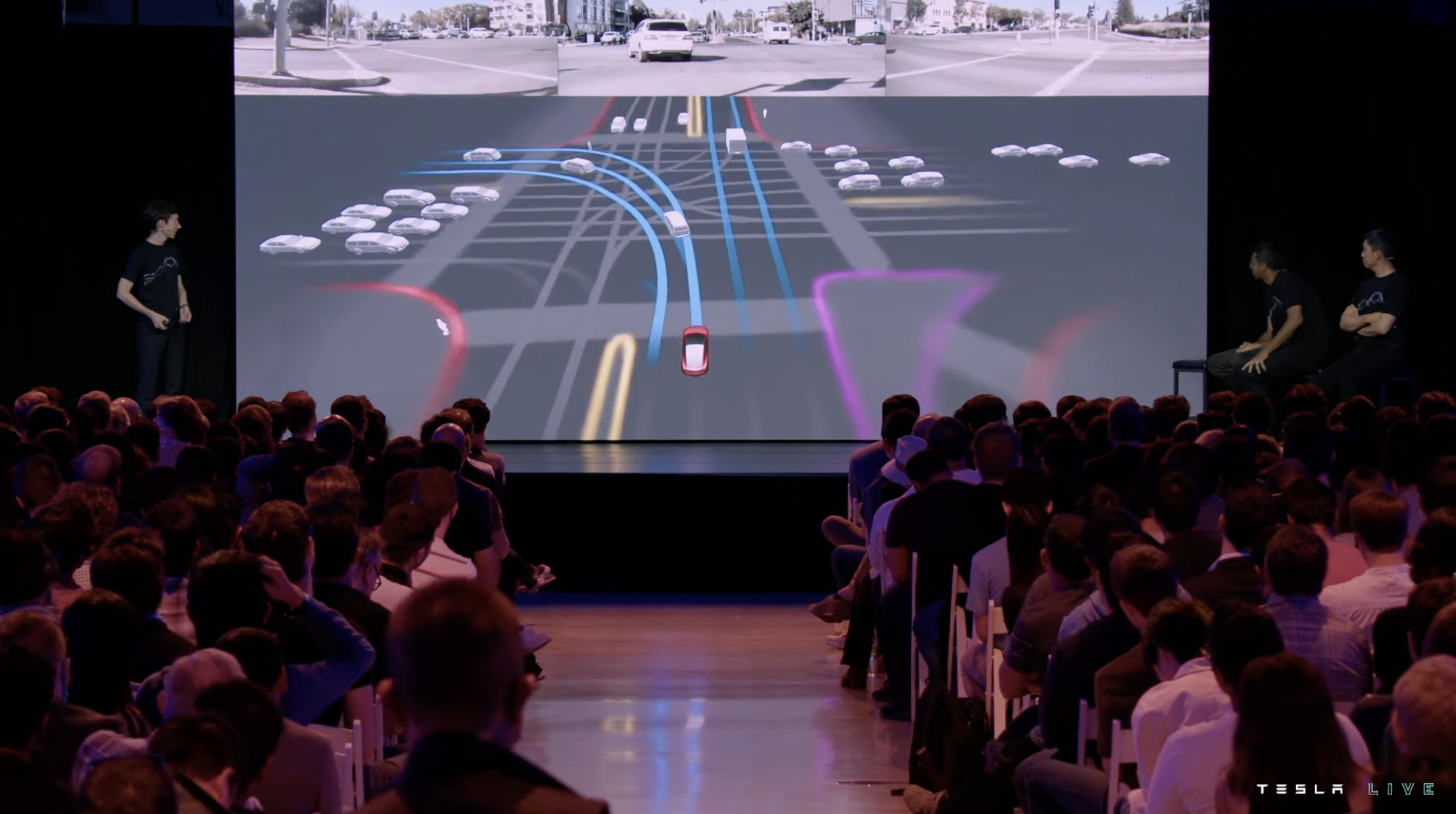
Tesla then introduced two other route prediction cases. The case on the left side of the image below depicts the system predicting the possible routes of a vehicle running a red-light who is heading in the opposite direction when passing through the intersection. For instance, the system may predict that the vehicle will go straight, turn left, or make a u-turn, and then determine the vehicle’s actual route based on its driving path to make a more reasonable avoidance.
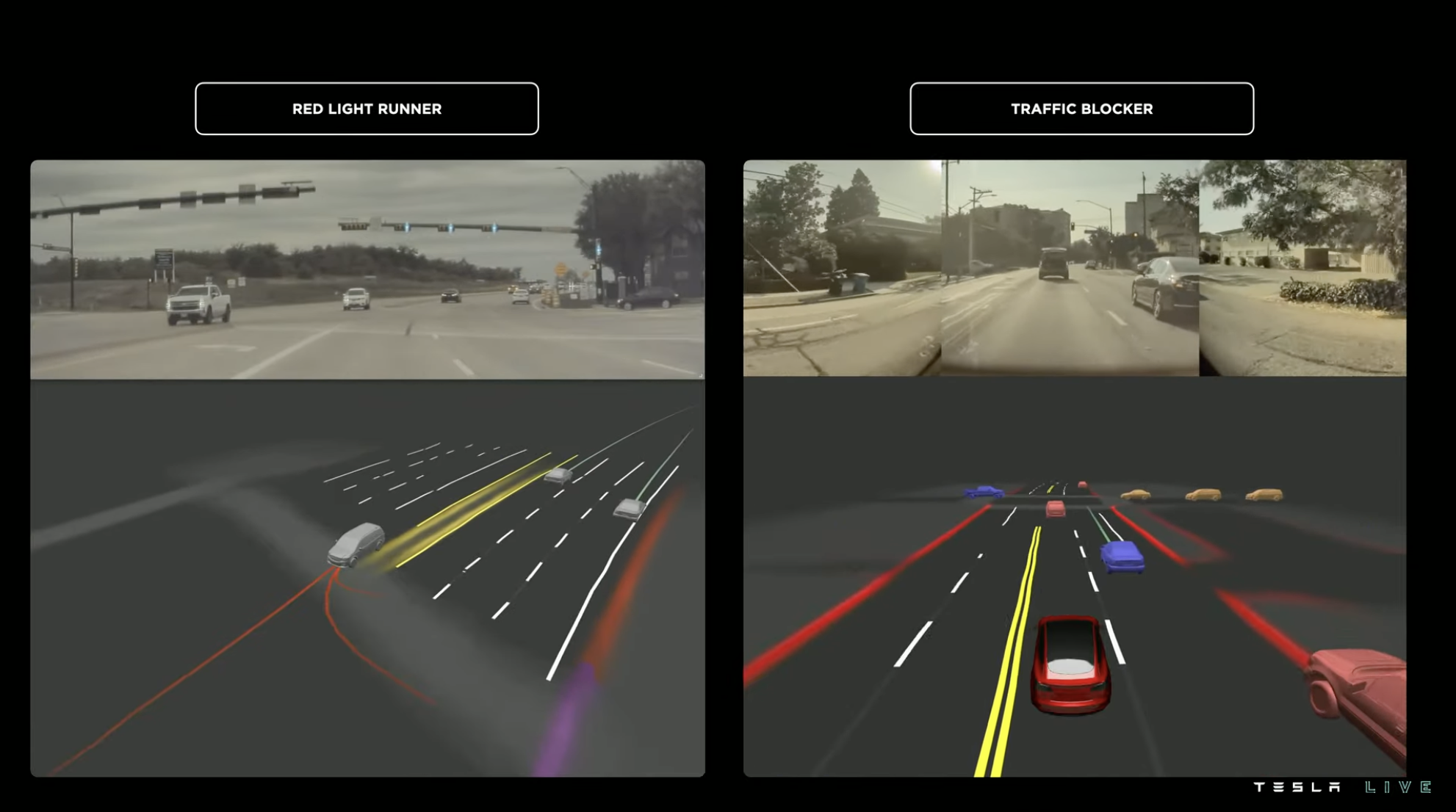 The image on the right is a case that better reflects the system’s semantic interpretation ability. There is a vehicle with double flashlights on the left lane of the intersection, even though the traffic light was red at the time and the vehicle on the right also eventually stopped and waited for the red light. However, the system judged that the vehicle on the left with double flashlights was not in a normal state of waiting for the red light, and the vehicle might not be able to move when the light turned green. Therefore, the vehicle changed lanes to the right in advance and waited for the red light in the right lane.
Therefore, the system’s predictive information not only includes features, positions, trajectories, and routes but also recognizes the target’s feature attributes. Because the real driving environment is constantly changing, the system needs to be able to respond to various variables in a short period. Therefore, the delay must be kept as low as possible.
The two stages of perception are the perception of objects and the environment in 3D states and judging the attributes and intentions of the target object through tensor data of the 3D environment and other additional information, and allocating system resources to targets with higher priorities.
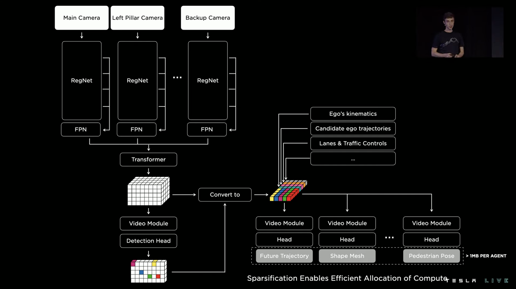
More than 1,000 NN signals, none of them is simple
The previous section introduced the path perception system that generates the “route statement” of the road, making it a key point to achieve single-vehicle intelligence by allowing this system to perform localized computation. The module that handles this task in the FSD chip is called the “TRIP ENGINE,” which has a simple function and the characteristic of being able to achieve highly efficient dense point prediction.
The FSD chip was put into mass production in 2019. Tesla didn’t anticipate running such a set of models three years later at the hardware design stage, so Tesla’s challenge here is how to use one hardware to do the complicated task beyond its original design purpose.
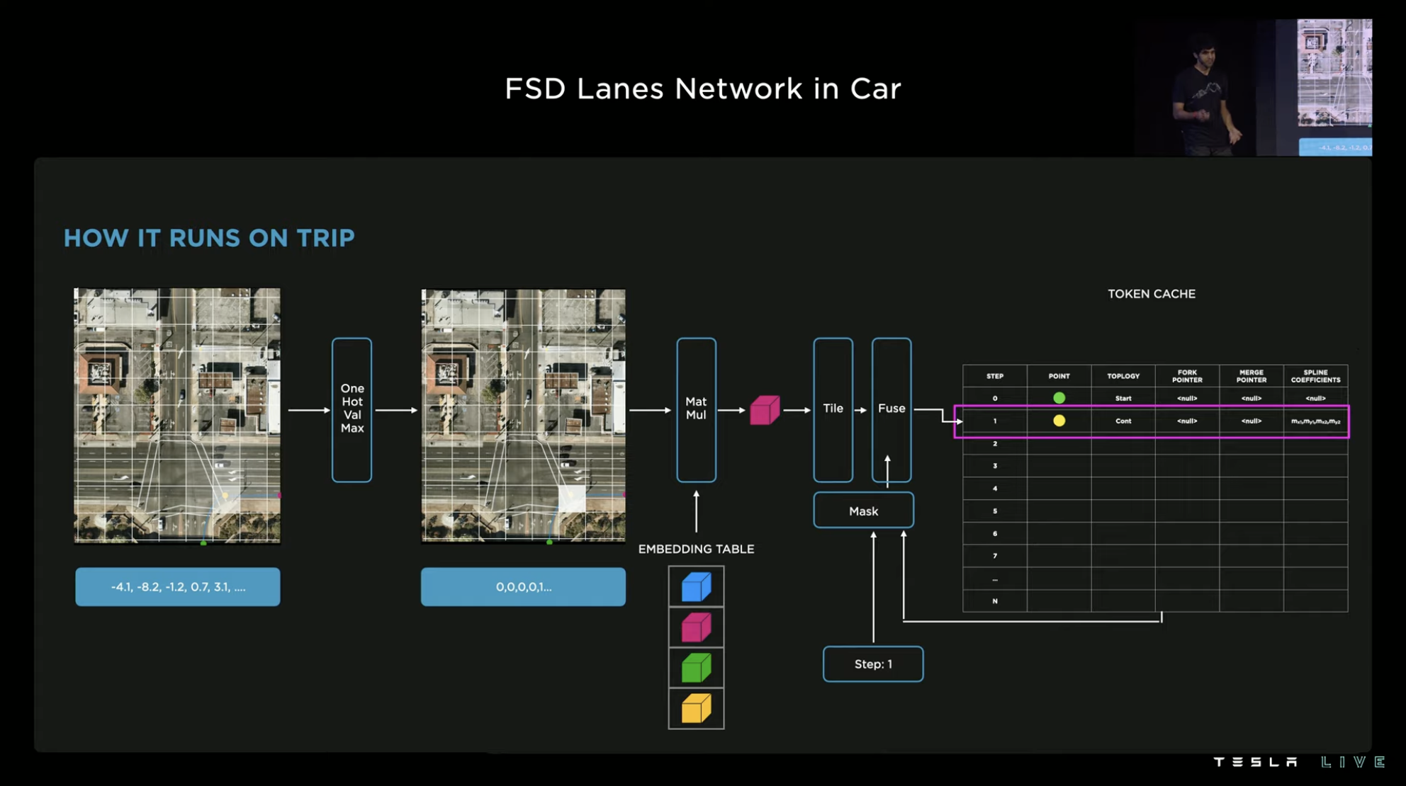
The Tesla FSD team ultimately solved this challenge using a creative method of importing node caches with embedded tables and iterating multiple times. The entire operation only uses the dense point prediction engine “TRIP ENGINE.” In fact, to make the whole process compilable, the team made a lot of efforts to improve the accuracy of grabbing and optimize performance in various aspects.
In terms of data, the final vehicle’s path neural network of FSD has 75 million parameters, a delay of 9.6ms, and an energy consumption of 8W.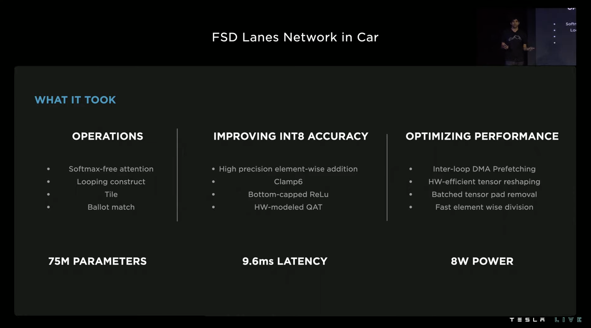
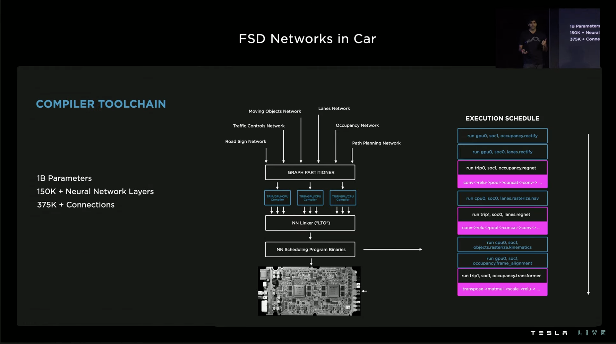
Among all the architectures, models, and networks running in the entire system, TRIP ENGINE is only one of them. There are more than 1,000 neural network signals under the FSD neural network system, containing over 1 billion parameters.

The massive neural networks also bring massive compilation tasks. Over 150,000 neural network layers and 375,000 neural network connections need to be compiled through a specialized neural network compiler and a conventional editor. First, the neural network image splitter is used to segment the images in the neural network into independent subgraphs according to downstream hardware. After being connected by the neural network linker and the traditional linker, they are optimized for linking time before being scheduled for programming into instructions executed by the system.
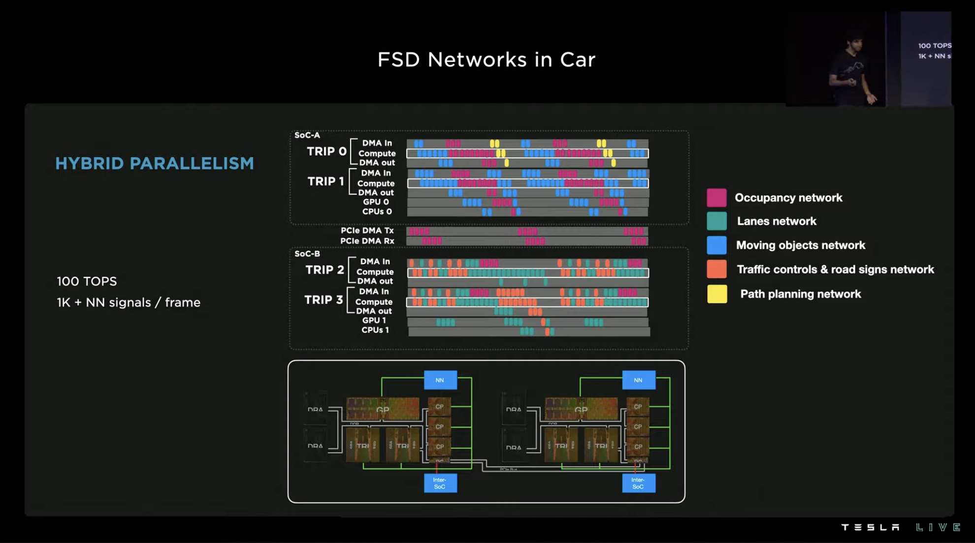
At the hardware level, the two SoCs in the FSD chip process various networks in a task-oriented manner. After optimization and performance improvement at each level, over 1,000 neural network signals can be output by the system per frame under the 100 TOPS computing power.

Auto-Labeling: Fundamental Ability of Generalization
In the FSD section, Tesla demonstrates various capabilities, all of which are obtained through extensive machine learning training, except for building software architectures. Achieving the ability generalization for different areas through rapid learning is an important part of FSD’s improvement of usability and safety.
For example, for the FSD route prediction model mentioned earlier, Tesla believes that to achieve good ability generalization, the training task volume would exceed one million intersections. However, how to solve the problem of such a large number of system training and supervision?With the increase in Tesla’s delivery volume, there are more and more Tesla models on the road equipped with FSD chips. As a result, the amount of data collected by Tesla is increasing day by day, with 500,000 new routes being collected daily. However, transforming collected data into usable training materials is a significant challenge.
Since 2018, Tesla has been training its software using a combination of manual and automatic annotation methods. At the beginning, the automation level was relatively low, and the range of automatable segments was limited, resulting in low efficiency. However, Tesla’s annotation efficiency has increased nearly 100-fold from 2018 to 2020.
Recently, Tesla introduced the latest multi-route reconstruction and automatic annotation machine, which reduces the labor time for marking the routes of 10,000 roads from 5 million hours to only 12 hours with machine annotation.
The implementation of this new form of annotation includes three key steps. The first step is precise trajectory reconstruction based on an 8-camera visual perception system. The vehicle collects video data, self-IMU navigation data, and mileage data to create a road model in vector space. Trajectory reconstruction size accuracy is 1.3 cm/m, with an angle error of 0.14°/m. The second step is multi-route reconstruction merging, which can splice and merge the reconstructed environmental information collected by different vehicles. The system splices different routes, aligns the same route, and fills in missing information on the road surface, thereby obtaining a more complete model of the road environment. After the system annotates the reconstructions, they are manually reviewed and finalized.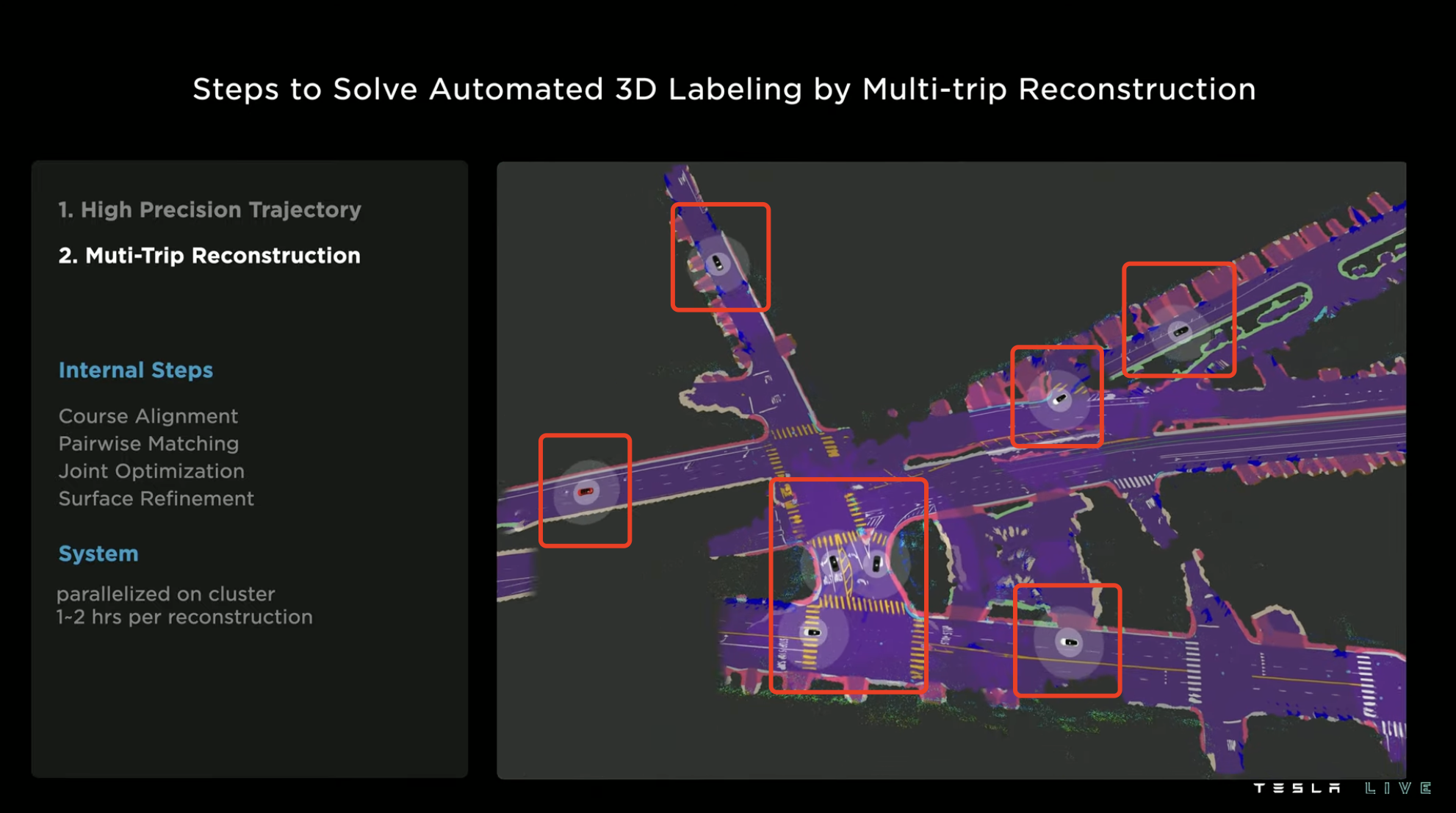

As the whole process mainly relies on the automatic operation of cloud computing system, the reconstruction process usually only takes 1 to 2 hours.
The third step is to continuously add new routes to the model that has been reconstructed in the first two steps. The automatic annotation of each new route only takes 30 minutes, while it takes several hours if done manually. Therefore, the speed of scaling the 3D reconstruction model mainly depends on the amount of new route data and the computing performance used for training.
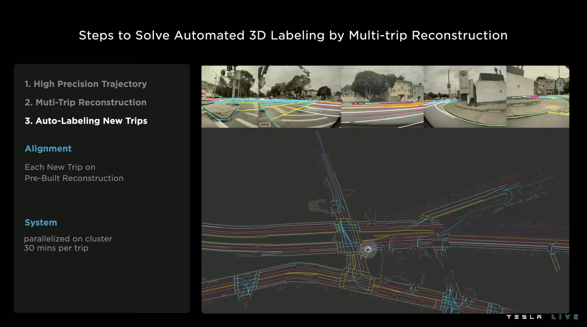
During the process of collecting materials, the situation of the same environment may also change, such as lighting, weather, traffic, etc. However, the materials of the same route can be collected through multiple vehicles running multiple times, so the quality of the reconstruction model can also be continuously improved.
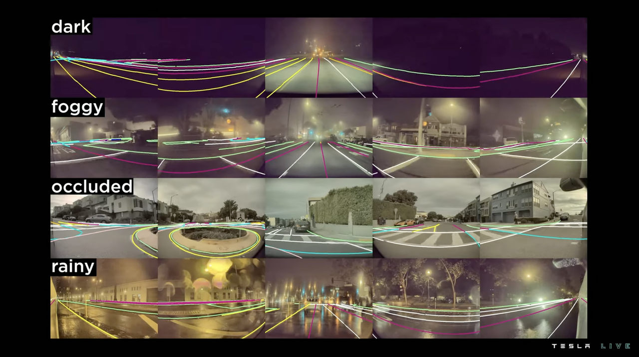
Lane annotation is just one of the many annotations in Tesla FSD, and many of the other types of annotations have automatic annotation mechanisms, and even some of them are completely automated.
Tesla’s team describes its automatic annotation as a data factory, where raw materials go in at one end and a large amount of training materials are processed and output at the other end.
Reverse simulator: Tesla’s training metaverse
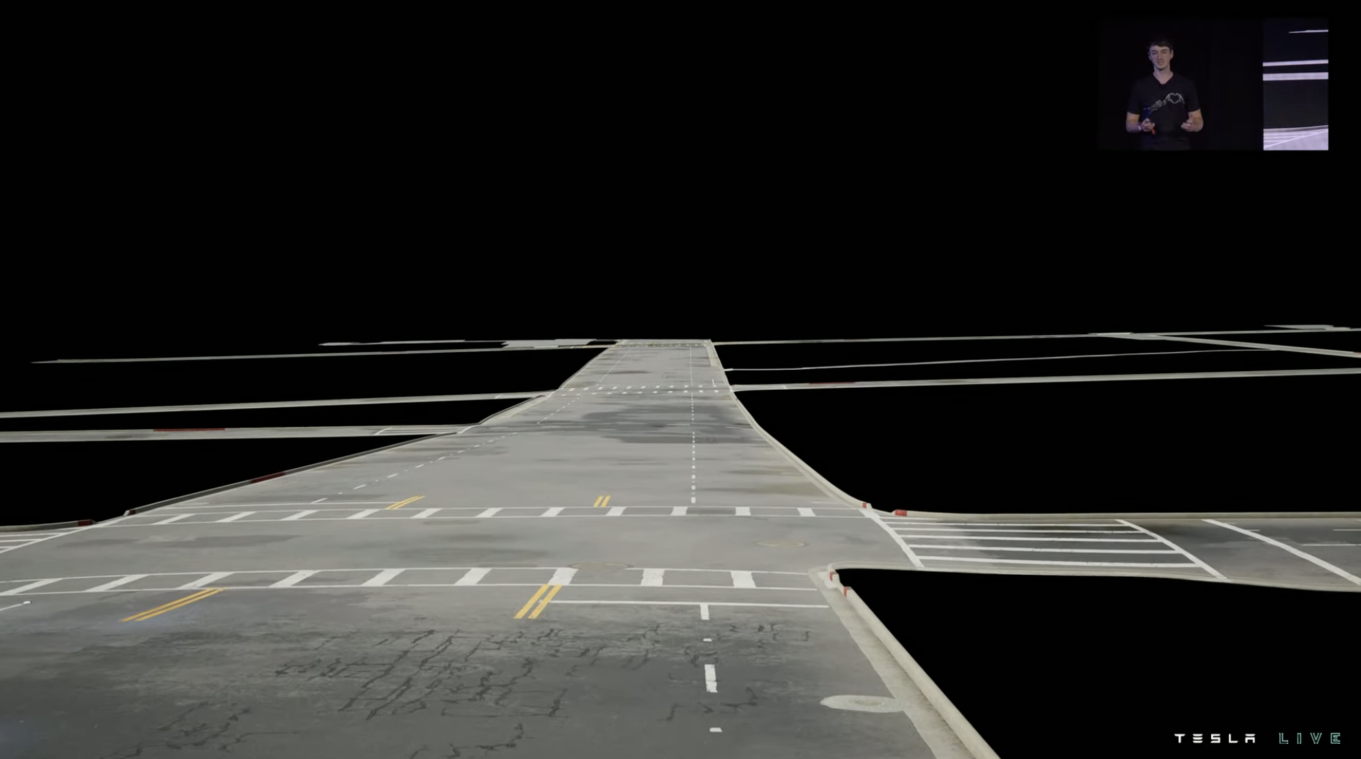
This intersection image is not a real photo, but a screenshot of Tesla’s training simulator. In the eyes of Tesla’s team, it is unacceptable to spend two weeks on manual construction of this scene.
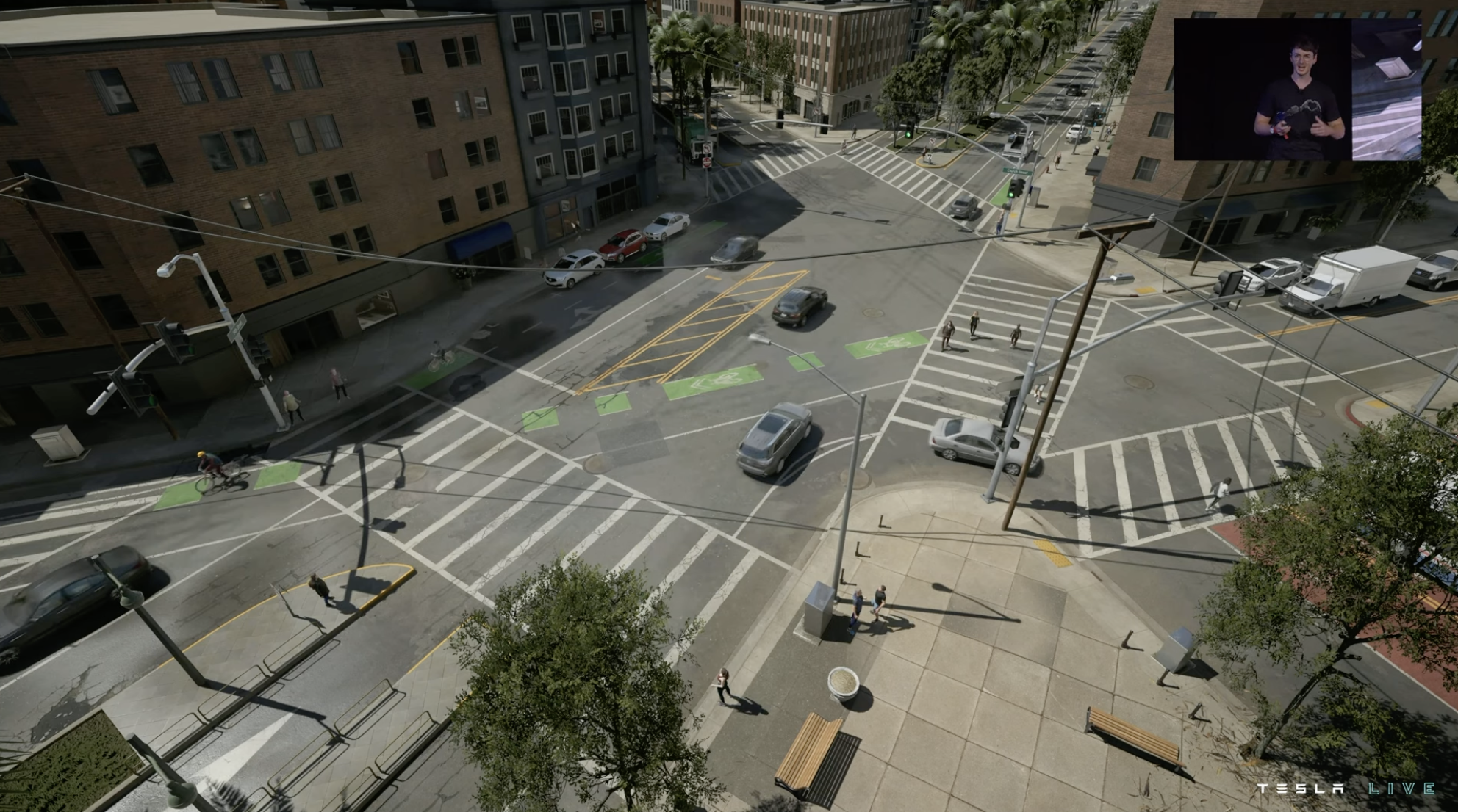
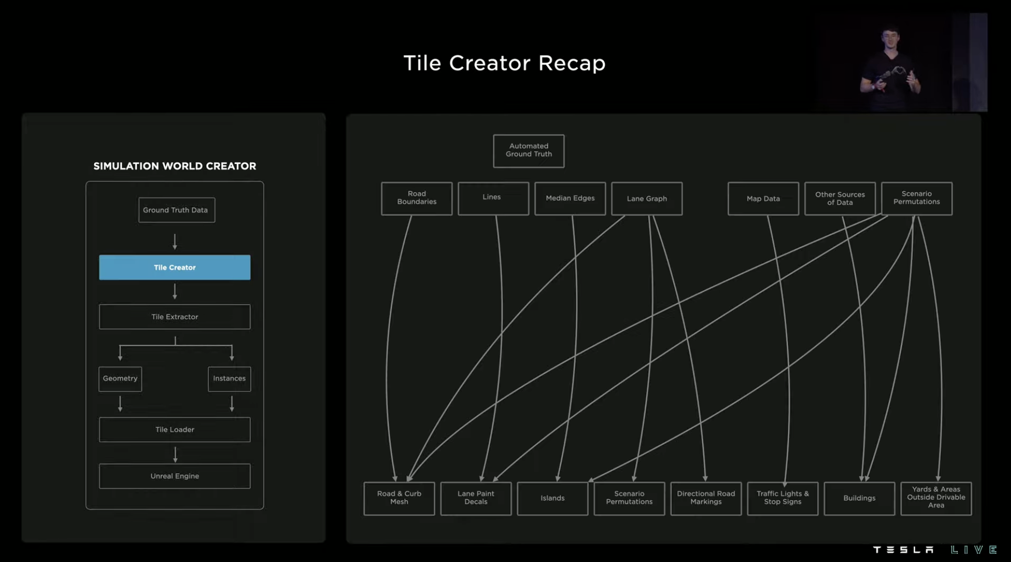
So Tesla turned to the method of automatic annotation of ground environment. With the help of new automation tools, a machine-generated similar simulation environment only takes about 5 minutes, which is nearly 1,000 times more efficient than manual construction.The automated construction process starts with the road surface information (including pavement, lanes, shoulder, etc.), and the system generates a simulated road surface and completes the rendering based on this data.
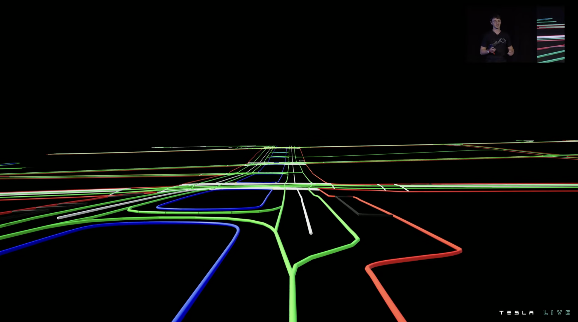
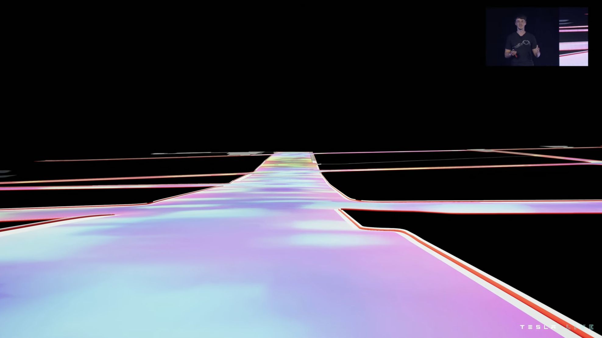
Then, based on the lane information, the system generates various types of lane and traffic lines on the road.
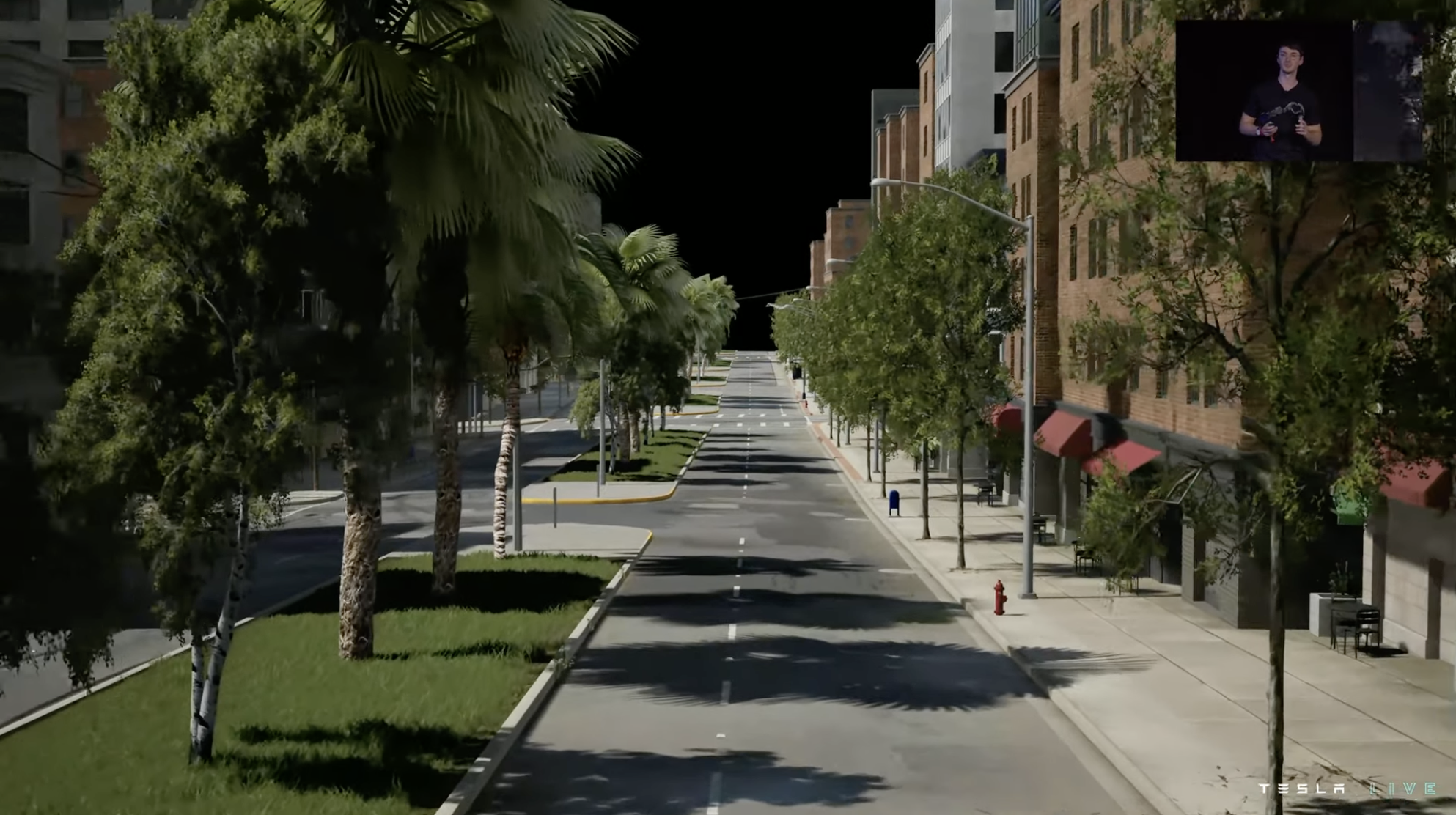
Next, the system randomly generates environmental features for shoulder areas, such as green belts in the center of the road shoulder, sidewalks and buildings on either side of the road shoulder. The system will also randomly generate objects such as fire hydrants and trash cans, and the generated vegetation will drop leaves like in the real world.

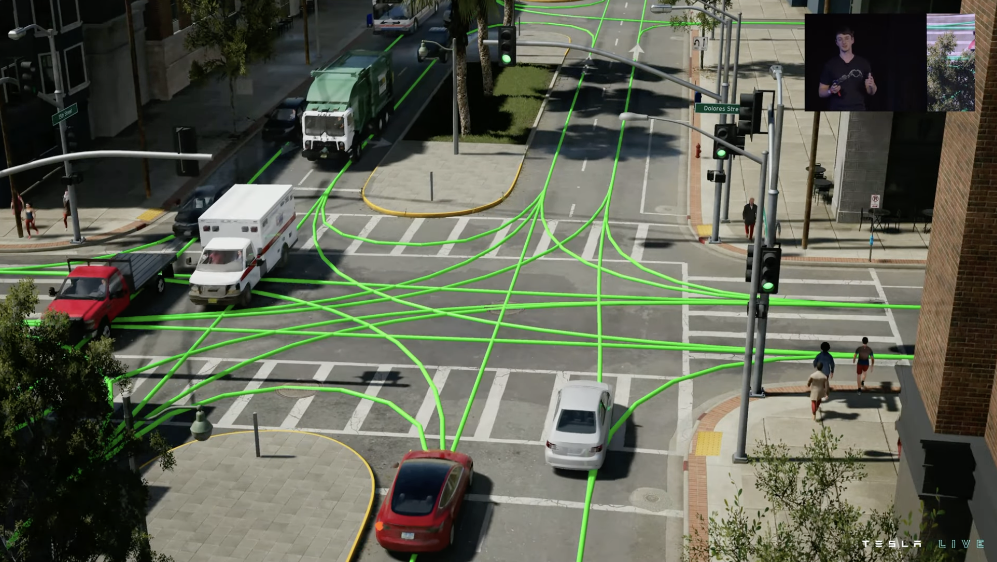
At intersections, the simulation system generates corresponding traffic lights and vehicle flows based on the route node information.

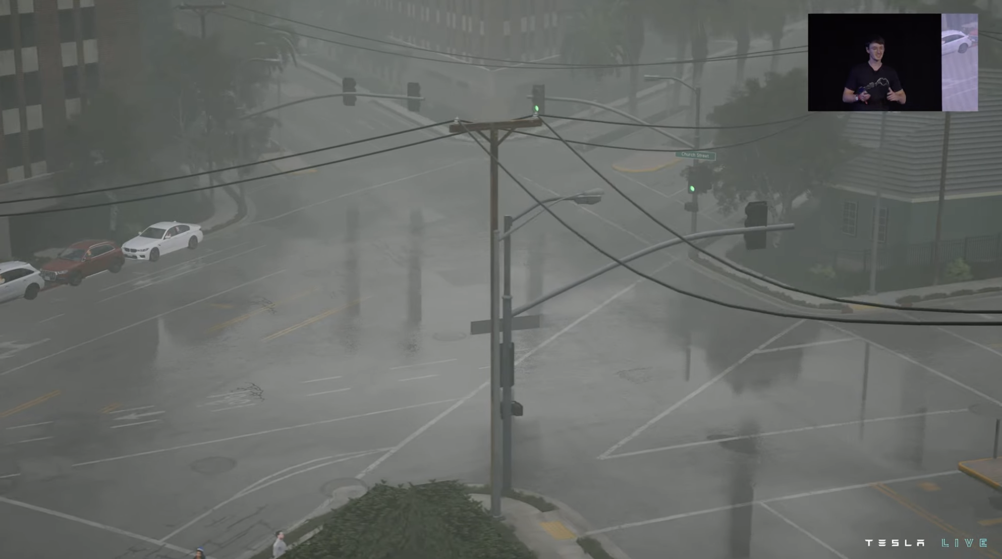
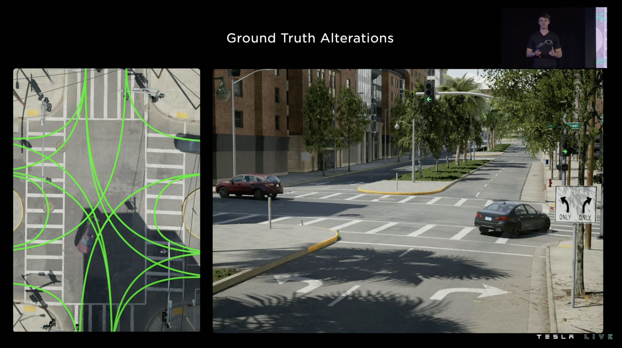
After the simulation environment is generated, Tesla can make rich custom variable modifications to this environment, such as various traffic participants, buildings with different regional characteristics, environmental weather, lighting, accumulation of water, and so on.


And to further test, the road signs for intersection can be modified to change the route, testing different scenarios of the same junction. This allows Tesla to have a more comprehensive range of testing scenarios, some of which would be difficult or impossible to collect in the real world.

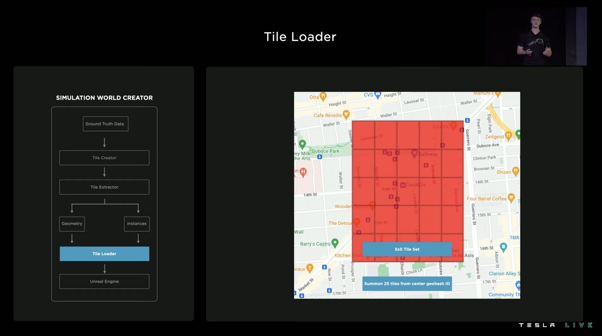
The Tesla reverse generator generates real-world road sections in blocks of 150㎡. The generated simulation environment can be saved and loaded at a later time, or combined with other blocks. A group of tiles can be arranged in a 5 x 5 or 3 x 3 pattern, and Tesla typically creates environment simulations for areas with heavy traffic or for areas that are interesting to study.

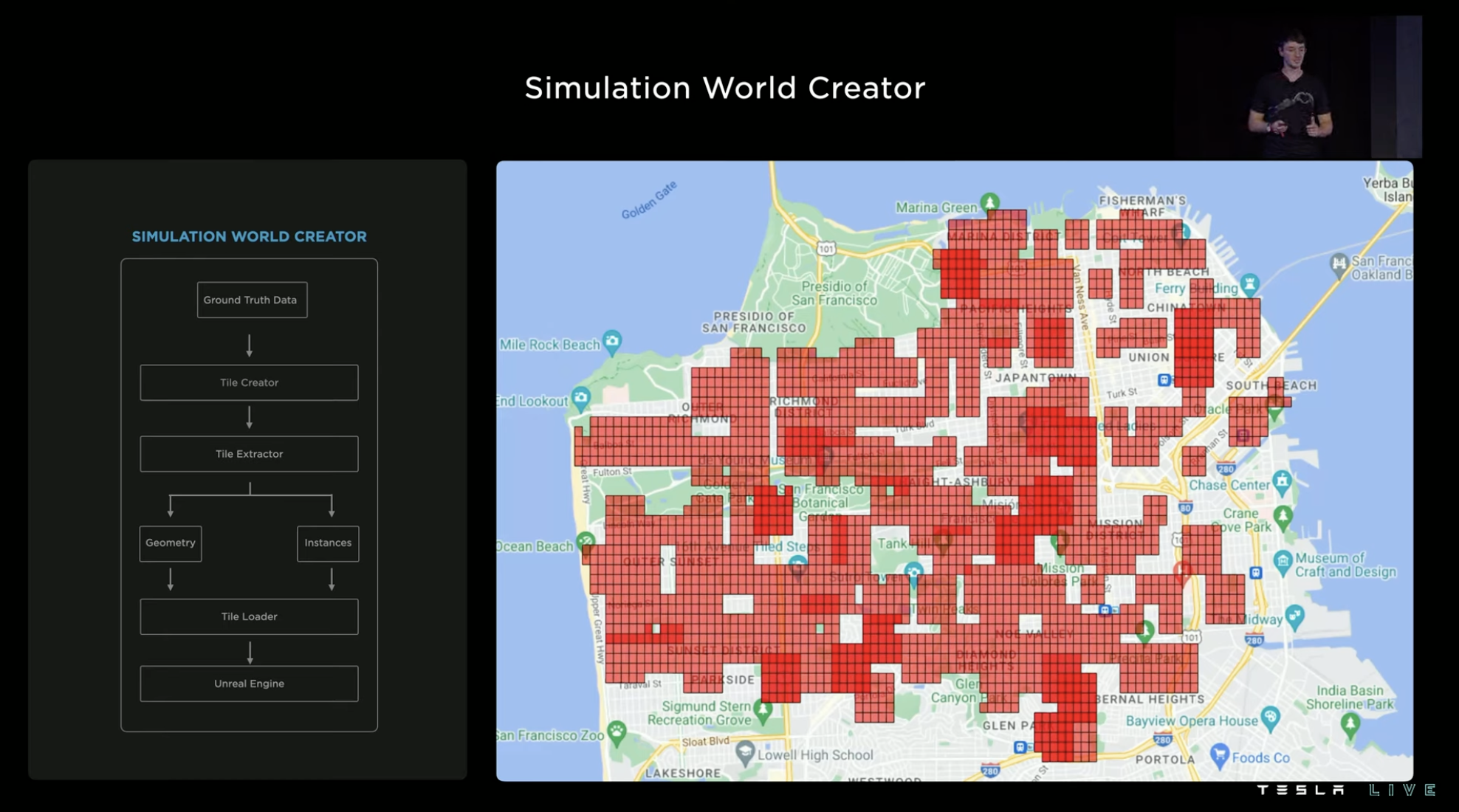 If building a simulated environment manually, the time required will be very long as the scale grows. However, with automated modeling tools, the efficiency will be greatly improved. For example, the simulated area of San Francisco in the picture can be generated in one day using Tesla’s training system. A large number of customizable simulated environments generated based on real roads effectively improve the FSD team’s training in various special scenarios.
Data Training: How Experienced Drivers Are Trained
The main function of data training is to help the system correct some erroneous logic. In the case in the picture, for example, the vehicle parked at the intersection should be treated as a static obstacle, but the system mistakenly recognizes it as the vehicle on the right waiting to pass through the intersection.
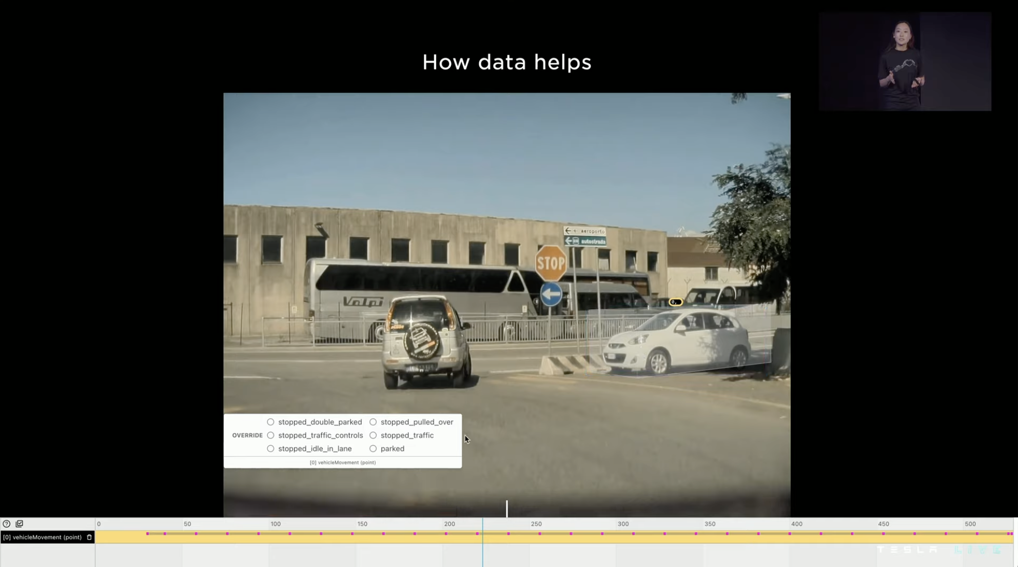
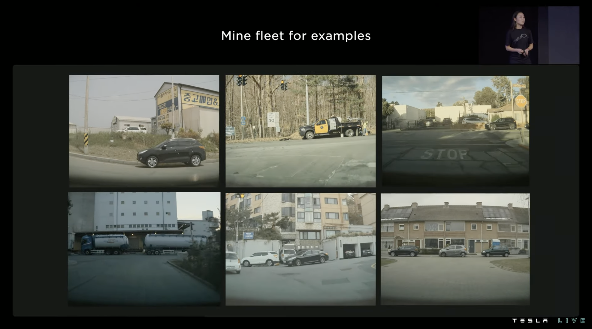
In order to let the system learn the scene, we need to find similar scenes from the collected videos as training materials. After learning and training from 13,900 videos, the system will not mark the intersection-parked vehicle as the vehicle waiting to pass through the intersection anymore, but will mark it as a red stationary vehicle instead.

Machine learning training is not only used for feature recognition and semantic understanding in FSD, but also for more refined aspects, even judging a signal of a vehicle’s movement.
At the same time, training is endless. The more training, the more accurate the system’s judgment ability. Tesla has upgraded the vehicle’s movement signal judgment five times this year, and the number of training and evaluation scenarios in each upgrade is increasing. The accuracy of the system has slowly increased from less than 90\% to over 95\%, approaching 100\%.
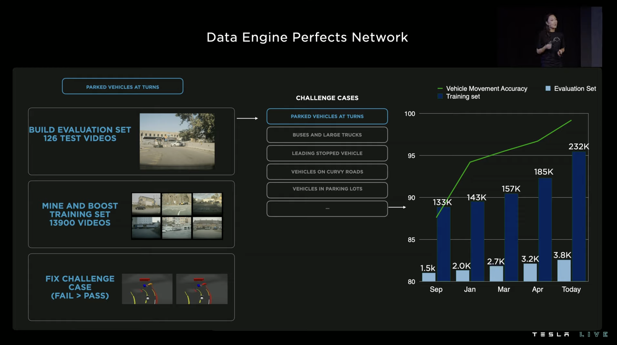
Similar training processes are used for almost all neural network signal judgment improvements. The size and data collection of Tesla’s connected FSD terminal is the source element of this closed loop. The computing resources required behind the training have also become an important focus for Tesla.
Summary II: FSD in the Era of Lidar
The debate over whether Tesla’s pure vision perception route selection is correct has never stopped. With the embrace of Lidar by China’s domestic new car makers, even the application of Lidar on 200,000 yuan-level models began to attract more and more attention to the commercial feasibility of Lidar intelligent driving.
It is certain that the cost of Lidar will become lower and the performance will become better. However, Tesla will not use Lidar even so. The cost problem of Lidar is only one factor in Tesla’s choice of a pure vision route. More importantly, the semantic information and perceptual logic of vision provided far exceeds that of other sensors.
On the 2022 AI Day, content about “perception” accounted for only about one-fourth of the FSD chapter. In terms of volume and distance perception, Tesla no longer emphasizes the “can or cannot” of vision, but emphasizes the perceptual accuracy of the system’s correct understanding of special scenarios.
In other words, Tesla is no longer inclined to emphasize the ability of vision to achieve 3D environmental information perception. It hopes to show the advanced nature of the entire FSD architecture to the world.
Today’s Tesla FSD has built a powerful systematic capability around its original ideas. Whether it is perception, regulation, training, or labeling, Tesla has sufficient reserves and strength to achieve “Full Self-Driving” in every major aspect of intelligent driving. And in every aspect, Tesla’s focus and investment in system efficiency also make the FSD business faster from the inside out.
In terms of map data, Tesla was very frank this time, stating that it used non-high-precision maps for importing various lane information at intersections in the city’s road perception stage. However, in the 3D road simulation stage used for system training, it can be clearly seen that Tesla adopted crowd-sourcing data collection in the United States. Given the current sensitivity of data, it is not known whether such operations are allowed in China. If prohibited, the cost of obtaining training scenarios for FSD Beta in the Chinese market will undoubtedly be higher, which will definitely affect the speed of iteration and upgrading.
Due to the strong localization properties of the two major factors for FSD algorithm training, cloud computing hardware and training materials, it is easy to predict that FSD Beta will have different states in different countries. If FSD Beta pushed in the Chinese market does not find ways to carry out special training for Chinese road scenarios, its actual performance may not be satisfactory.## Dojo: The Winning Strategy for the Next Stage
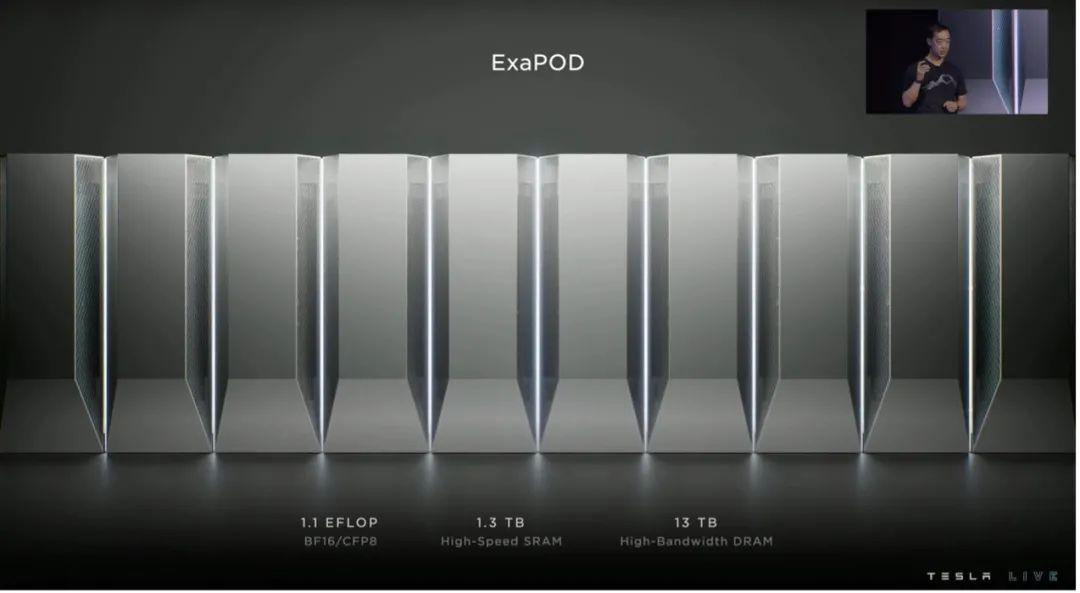
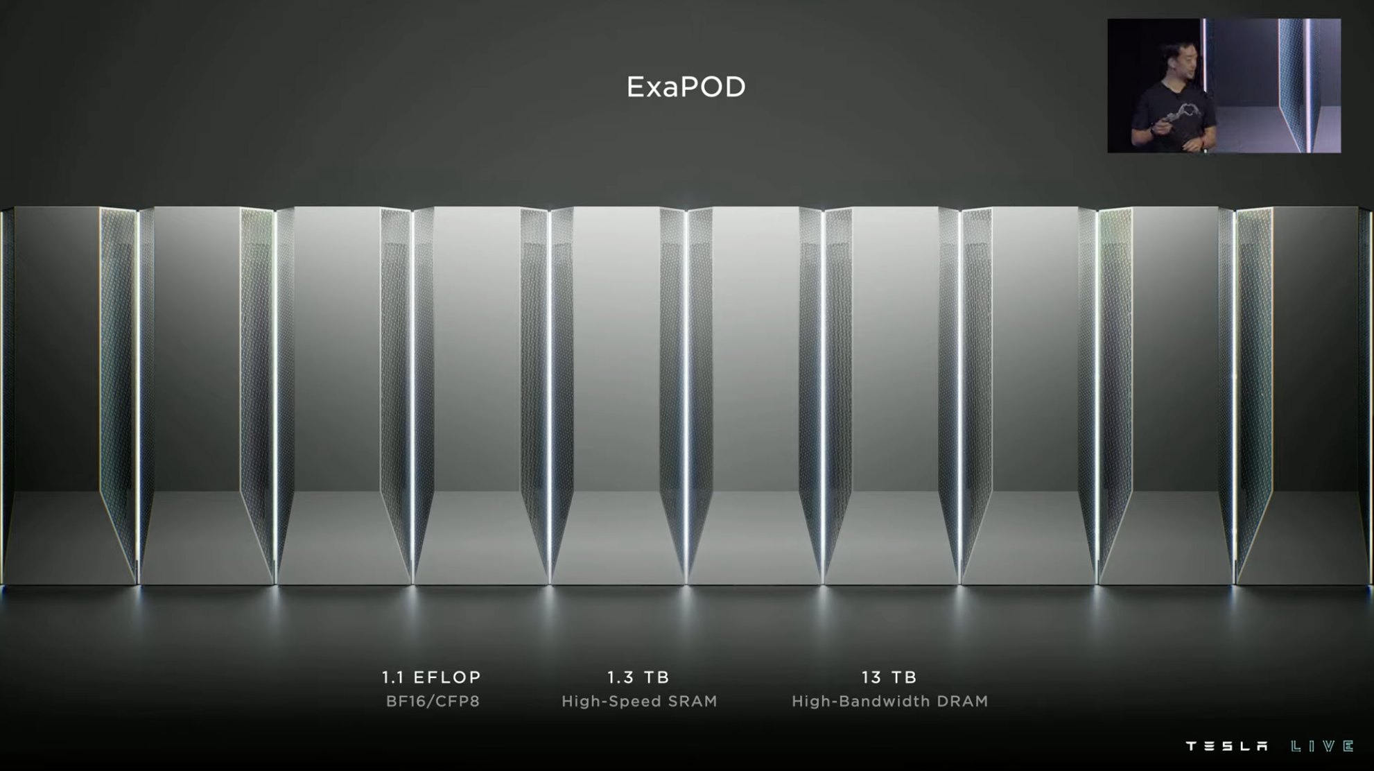
At last year’s AI DAY, Tesla showcased its independently developed first AI neural network training chip, Dojo D1, and also displayed the ExaPOD supercomputer cluster composed of D1. This year, the keynote speech of AI DAY was dedicated to Dojo.
The reason why such a powerful computing hardware is needed mainly lies in the fact that the speed of software training determines the progress and iteration speed of Tesla FSD, and the training time for some complex engineering projects has reached the level of charging on a monthly basis before the appearance of Dojo.
If Tesla can independently develop specialized training hardware with competitive performance and cost, it will be a win-win strategy for subsequent larger-scale training.
Therefore, at the beginning of the system design, the Tesla team focused on efficiency, and the computing power of this system needs to achieve high utilization rates even at a very large scale.
Memory Selection from Top to Bottom
Initially, Tesla tested using DRAM (Dynamic Random Access Memory) to build this system, but the experimental results were unsatisfactory. Therefore, Tesla decided to abandon DRAM and adopt SRAM (Static Random Access Memory) as the storage medium for the Dojo system, which was very unconventional.
The difference between these two storage media can be roughly described as follows: DRAM is cheaper, easier to make larger capacity, but consumes more power and is slower. SRAM is more expensive, has much smaller capacity, but has faster speed and lower power consumption.
The reason Tesla chose SRAM as the core storage of Dojo is due to its speed. Although the storage capacity of SRAM is far less than DRAM, if high utilization of computing resources is to be achieved, the system must have high bandwidth and low latency, and SRAM has obvious advantages in this respect.
Such a critical decision often leads to many chain reactions. For example, if the system needs virtual memory, it requires page tables, but page tables also take up space, and the storage capacity of SRAM is already small, so virtual memory is not implemented.
In addition, there are no interrupts in the system, because the system’s accelerator is directly connected to the compiler, and the compiler is responsible for all scheduling content, so the system itself does not need interrupts. In short, Tesla’s design of the system is quite unconventional in a series of system designs.Tesla’s key pursuit in system design is “No Limits,” which can be understood as unlimited expandability and the freedom to combine computing power. The team hopes to create hardware with a highly flexible and unrestricted approach, but in many cases, computing hardware like GPU, CPU, and DRAM are combined according to certain ratios. In this scenario, if stronger performance is needed, an entirely new system with stronger performance is usually required.
The Tesla semiconductor team aims to create a vertically integrated solution that considers both software and hardware, achieving high system efficiency, energy consumption and heat control, and full-stack system management.
To identify the various limiting factors in the system, the Dojo chip was experimentally used in FSD software training tasks early on, and the Tesla semiconductor team has gained a lot of experience and lessons from such practices over time.

Basic Composition and Performance of Dojo
Dojo D1 contains 50 billion transistors on a chip area of 645 mm², surpassing AMD Epyc Rome’s 39.54 billion transistors, but falling behind NVIDIA’s GA100 Ampere SoC’s 54 billion transistors, although the latter’s chip area is 826 mm².
D1 integrates 77.5 million transistors per square millimeter, with excellent effective transistor density and higher than NVIDIA A100 GPU and lower than Apple M1.
D1’s thermal design power is 400W, and the peak computing power under FP32 precision is 22.6 TFLOPS. For comparison, we can take out the NVIDIA A100 GPU again, which also has a thermal design power of 400W, but the peak computing power under FP32 is 19.5 TFLOPS.
Based on the D1 chip, Tesla has launched a system-level solution on a wafer and integrated 25 D1 chips into a training tile through TSMC’s InFO_SoW packaging technology. At the same time, Tesla integrates 12 training tiles into one cabinet.
Therefore, in the case of a 10-cabinet system, one ExaPod contains 120 training tile modules and 3,000 D1 chips, with more than 1 million training nodes, computing power reaching 1.1 EFLOP, and with 1.3 TB high-speed SRAM and 13 TB high-bandwidth DRAM.
Each training tile is composed of 25 D1 chips arranged in a 5×5 configuration and interconnected in a two-dimensional Mesh structure. It adopts a near-memory computing architecture with on-chip cross-core SRAM reaching 11 GB, but its power consumption also reaches 15 kW, with an energy efficiency ratio of 0.6 TFLOPS/W @ BF16/CFP8.
In addition, Tesla has developed the Dojo Interface Processor (DIP), located at the edge of the end board, to connect the training processor and CPU. Each DIP has 32 GB of high-bandwidth memory (HBM) and an external transfer bandwidth of 900 GB/s, totaling 4.5 TB/s. Each tile has a total of 160 GB of HBM.
The 40 I/O chips on the outer edge of each training module achieve an aggregated bandwidth of 36 TB/s or a cross-bandwidth of 10 TB/s.
Dojo’s Performance Bible: Density Achieves Performance
Building a huge integrated accelerator is the vision of Dojo. For software, it will be a single high-bandwidth, high-speed seamless computing platform.
The key to achieving this vision is Dojo’s “training tile.” Each training tile not only integrates 25 Dojo chips through extremely high bandwidth, but multiple training tiles can also be assembled into new training tile groups through direct connections.
High density is the concept that Dojo achieves high performance. This density refers not only to the density of transistors, but also to a series of links that improve system integration density such as downstream system density, power density, and heat dissipation density.
Since AI Day last year, Tesla’s first challenge in investing in software training for Dojo has been power supply. It is very exaggerated to let Dojo achieve high-performance computing for power density. The 12-phase independent power supply shown on the chip requires a total of 1,000 A of current, and the current per square millimeter reaches 0.86 A. Faced with such power supply requirements, Tesla has developed a multi-layer vertical power supply solution, and because the chip itself is composed of different types of materials, the huge power supply has also made the thermal expansibility of the materials a key concern.
In other words, if not controlled properly, the chip may crack and be damaged due to inconsistent thermal expansion between materials during operation.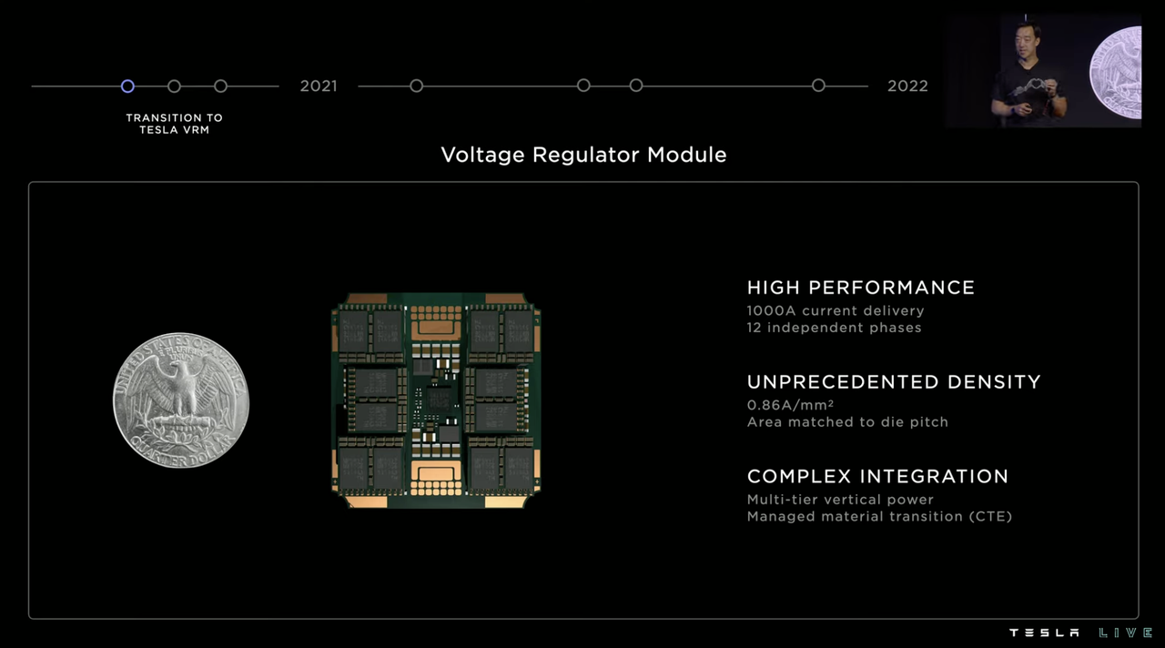
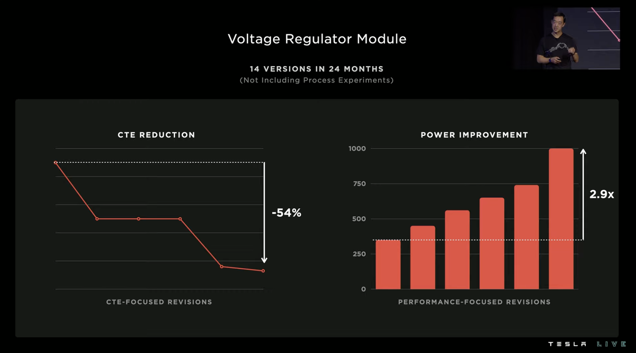
Initially, Tesla worked with suppliers to develop this power supply solution, but then Tesla realized that the system still needed to be self-developed. Over the next 24 months, Tesla made 14 versions of voltage regulator modules, ultimately reducing thermal expansion by 54% and increasing power supply current by 2.9 times.
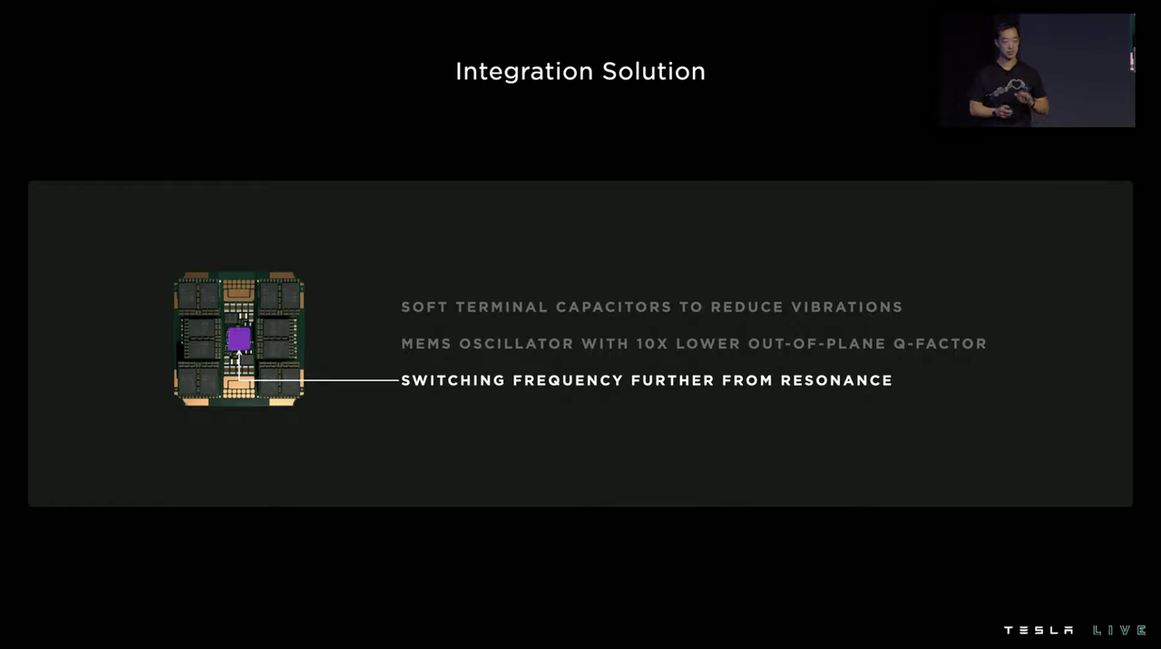
The vibration issue that followed was also a tricky part because the X and Y axes of the chip were designed for high-bandwidth communication, so there was extremely limited vertical space available on the chip for use. All components had to be integrated with the power supply, including the clock, power supply system, and system controller. When the current reached a certain level, the chip would vibrate due to piezoelectric effects, which would then affect the clock output of the oscillator by affecting the surrounding capacitors.
Tesla took three measures to solve this problem, using soft-end capacitor interfacing, avoiding resonance frequencies, and using a ten-fold reduction in micro-oscillators’ quality factor to reduce micro-vibrations.
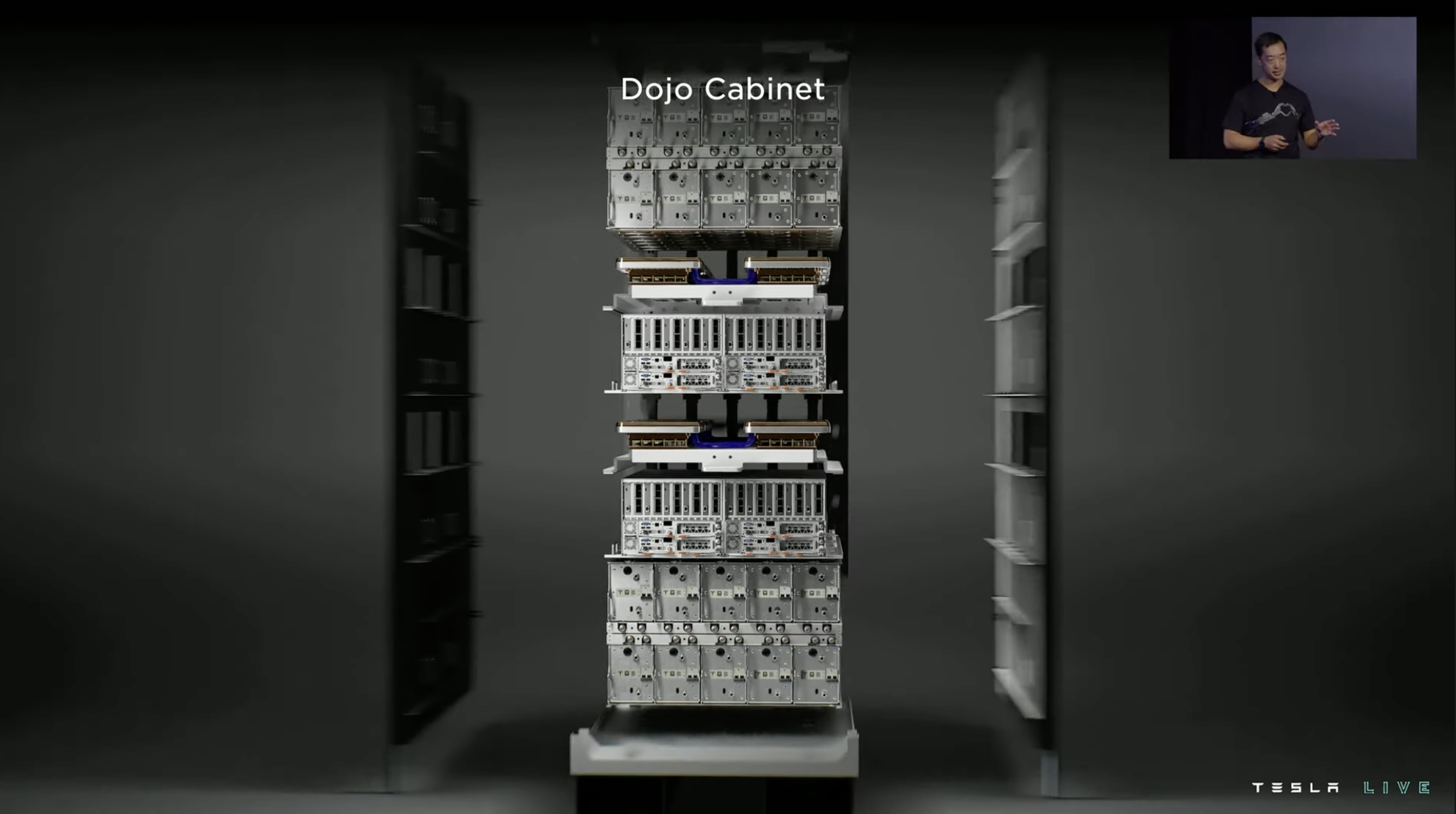
In addition to improving system density at the chip level, Tesla also optimized the external infrastructure to improve density. As mentioned at the beginning of the Dojo section, everything is built around improving system density. Therefore, in almost every stage of the “hardware group,” you can see high-density connections, extremely fast bandwidth, ample system power supply, and strong heat dissipation.


Training Center Emphasizes Combined Strength of Hardware and Software
After providing an overview of the hardware, Tesla introduces the role of software in the Dojo project, starting with the composition of “performance”. Performance is equal to chip computing power times integration level times accelerator utilization. Therefore, with relatively fixed hardware, improving the integration level of the system and the utilization rate of accelerators is the path to improving system performance.
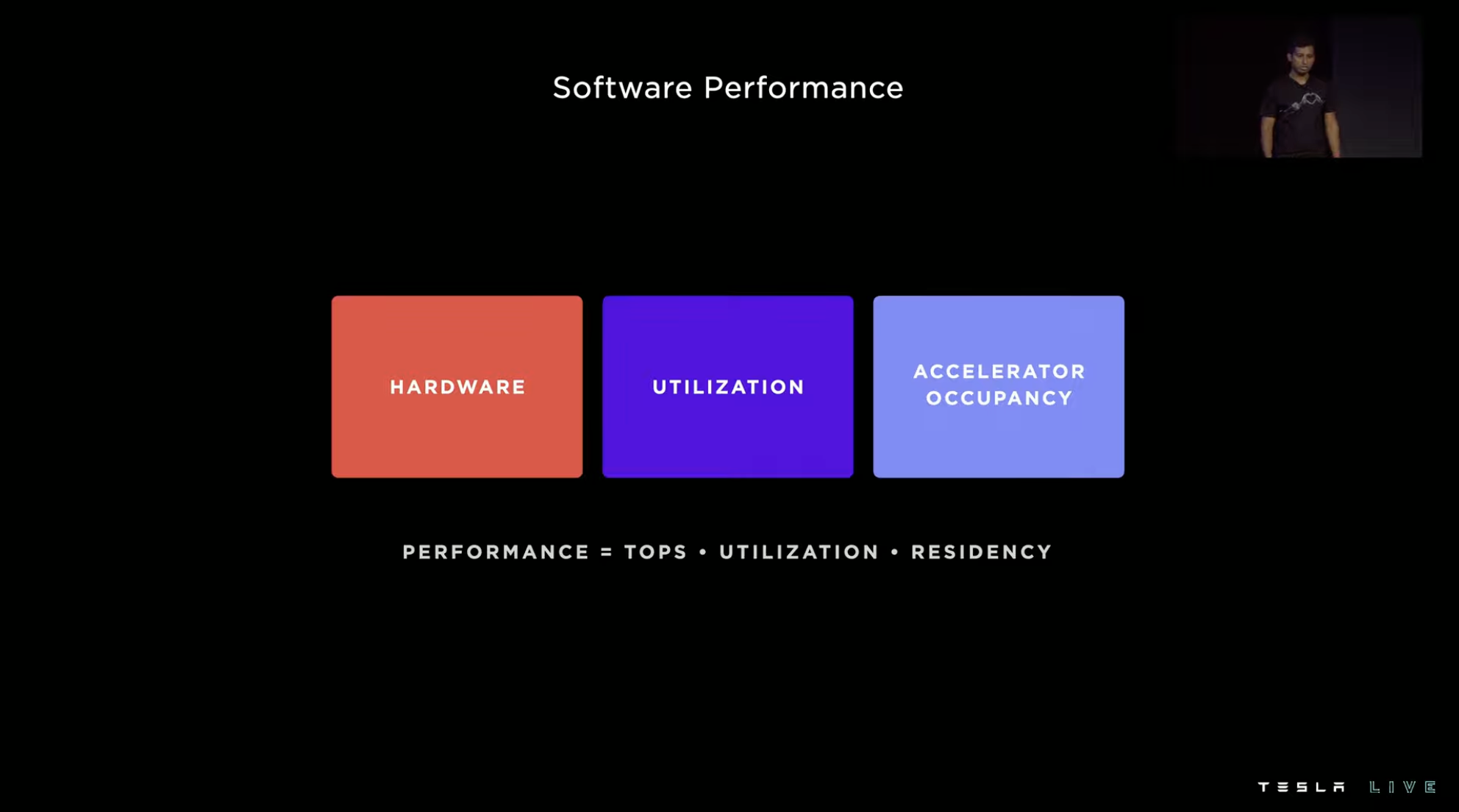
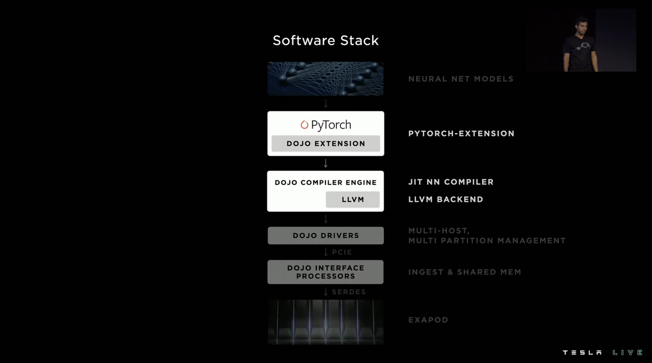
Improving the integration level mainly relies on improving the compiler, and improving accelerator utilization relies on improving data extraction.
Under the residual network model, as the number of accelerators increases, the system throughput almost linearly increases.
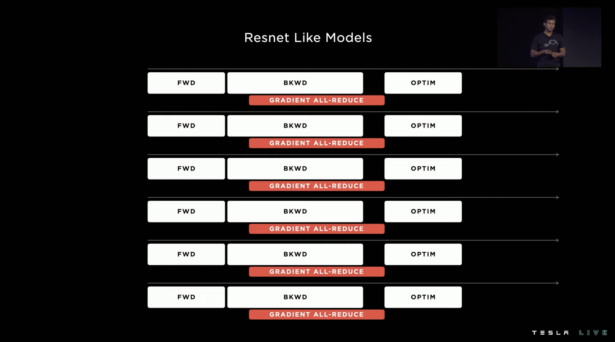
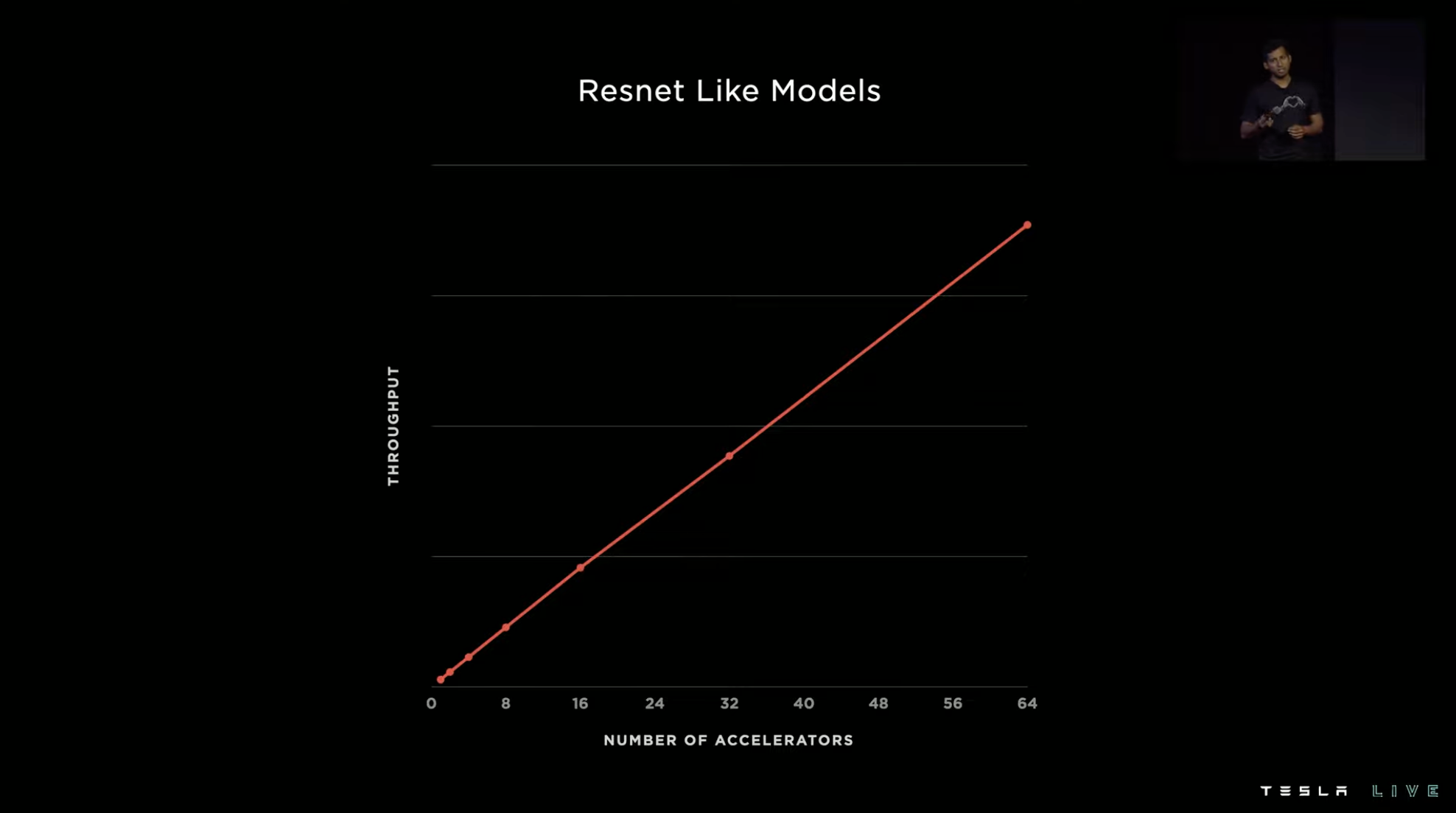
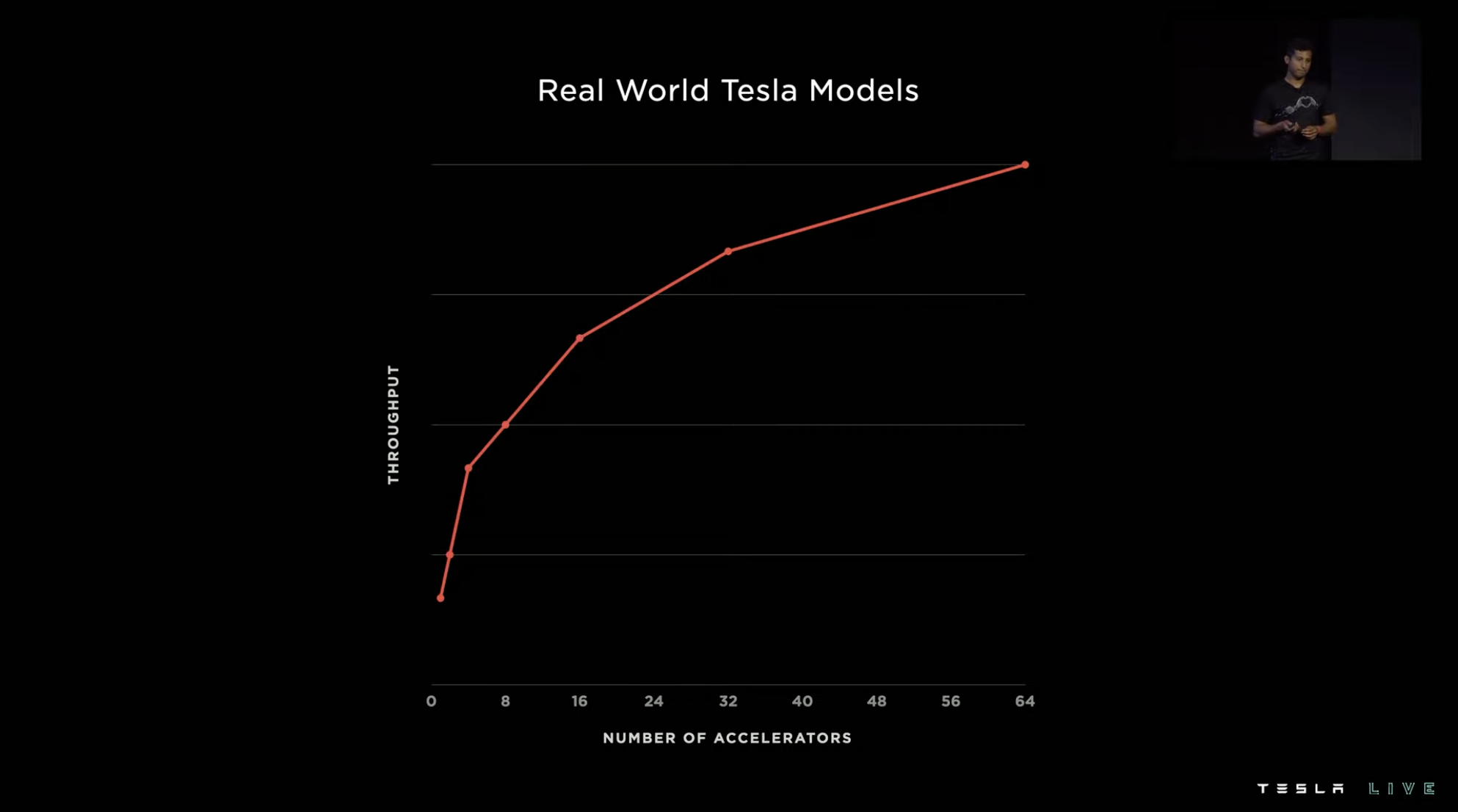
However, the actual situation of visual models is more complex, and the consistency of the system’s running pace will deviate, which will lead to a loss of system performance. Finally, as the number of accelerators increases, the system throughput does not increase linearly but instead the slope becomes flatter.
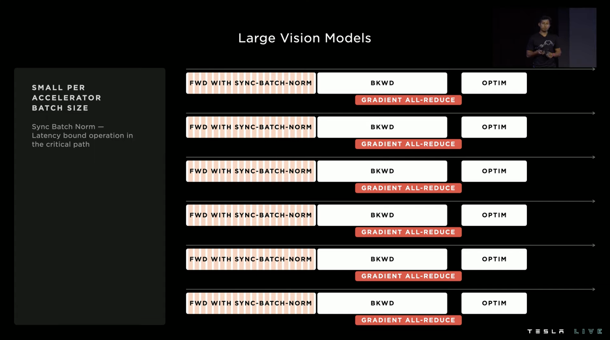
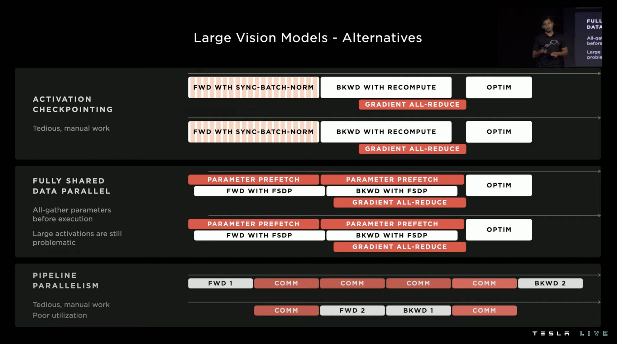
Dojo’s computational group considered this problem early in the hardware design. Therefore, through various hardware structures, it achieved the effect of a single large accelerator while accelerating the multi-hardware parallel accelerator becomes stronger.
In order to match this hardware design, Dojo’s compiler uses batch continuous coding and introduces a candidate mechanism, allowing signals:
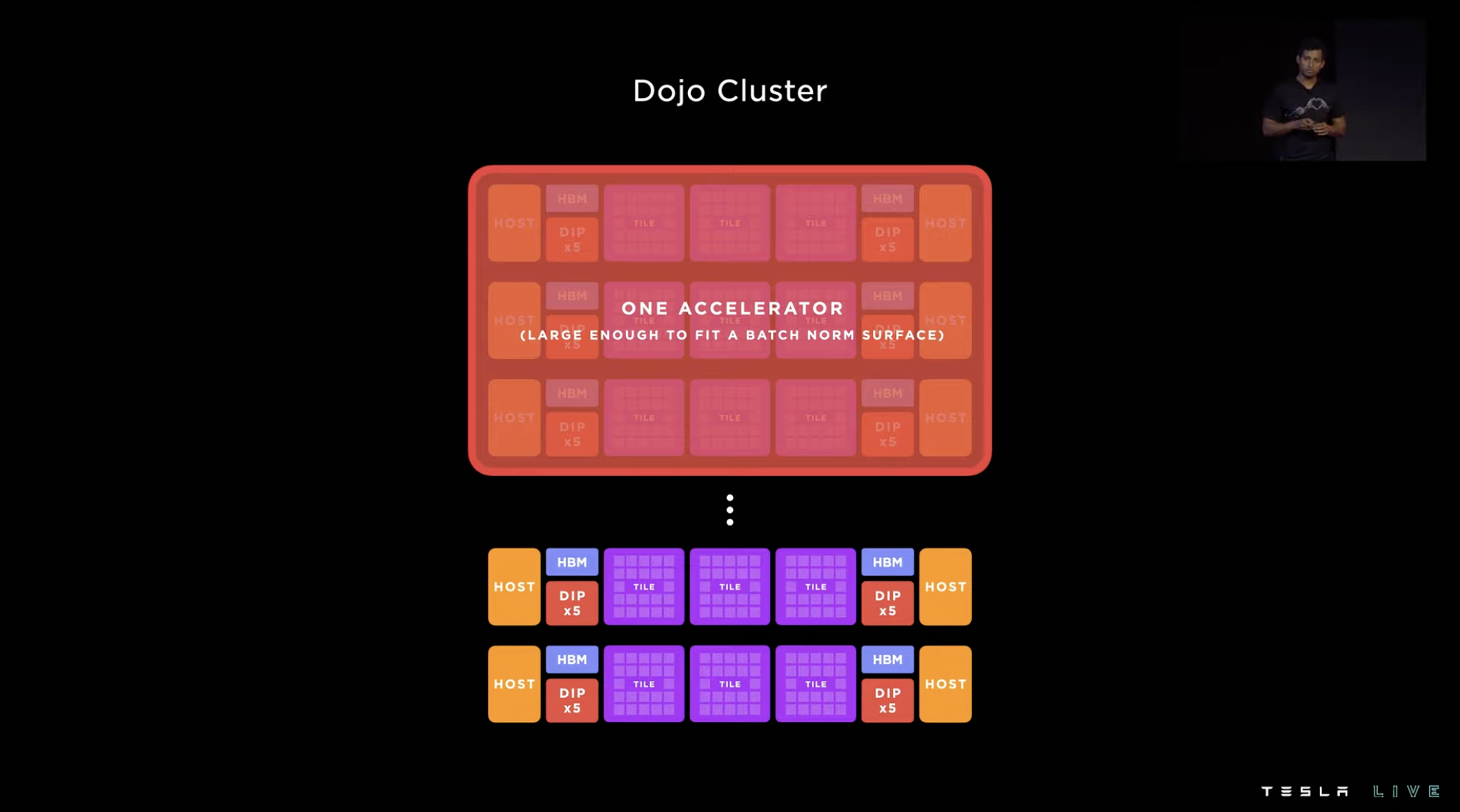
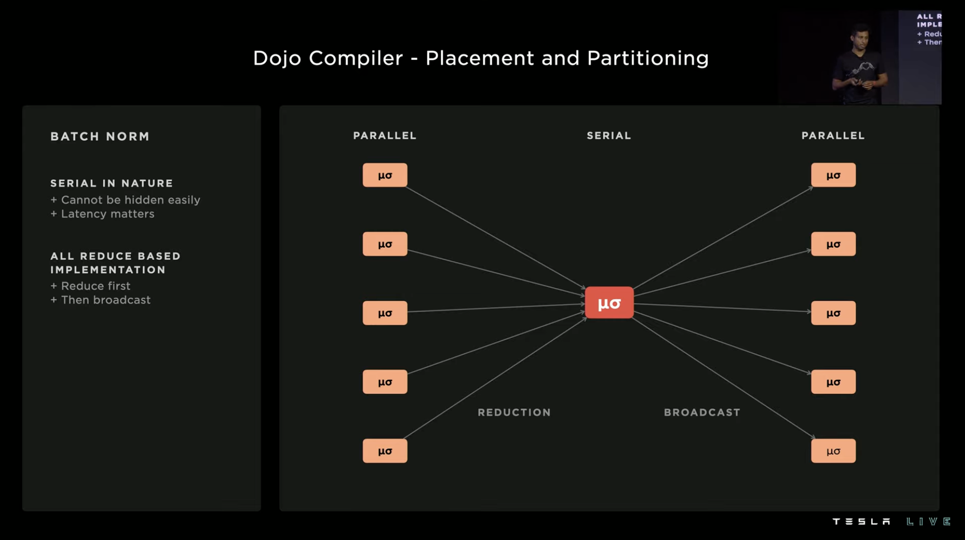

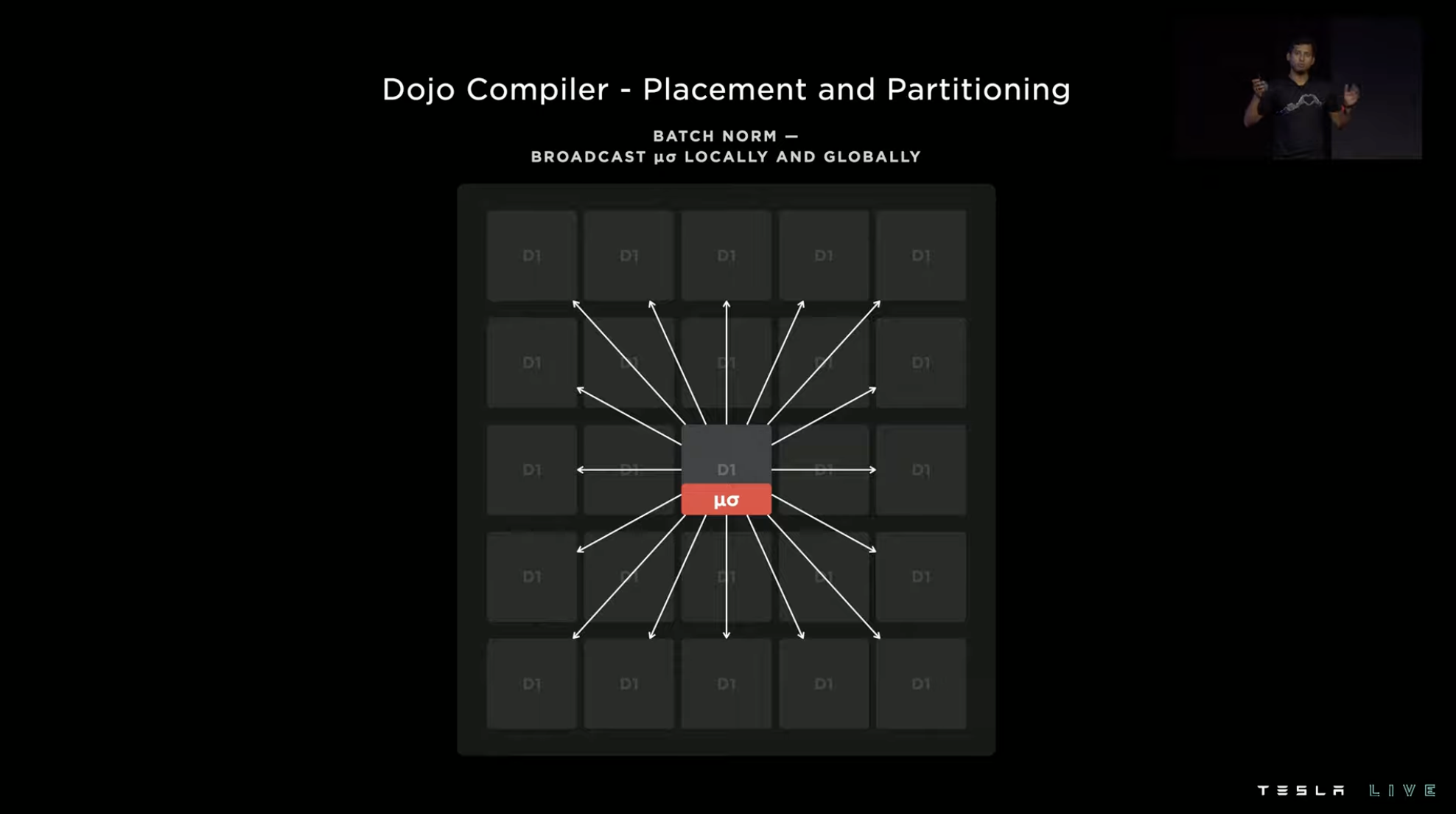
Excessive Beatdown of Nvidia
Software optimization with Dojo has a significant final effect, with an instruction delay of 150 us under 24 A100 GPUs, but only 5 us under 25 D1 chips.

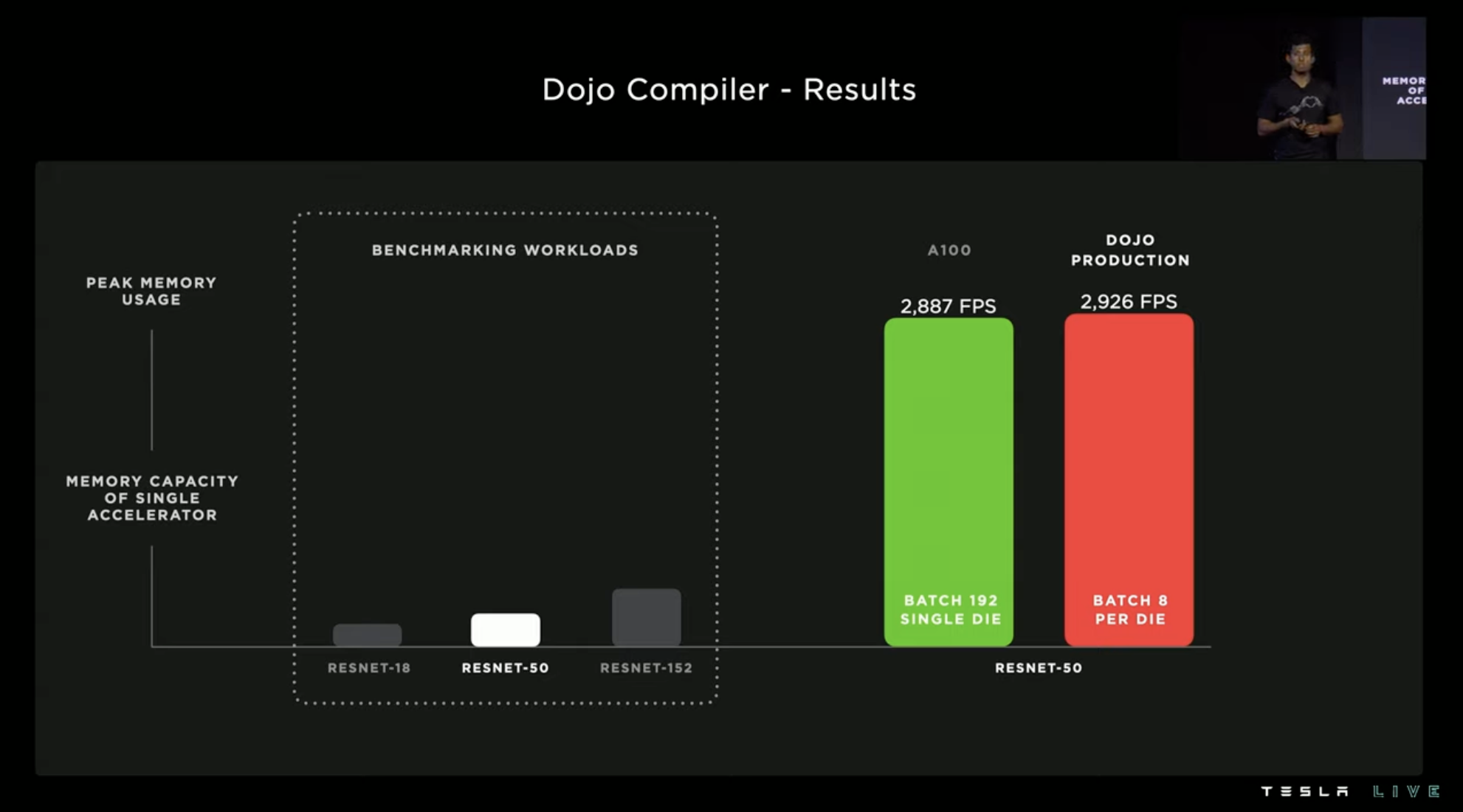
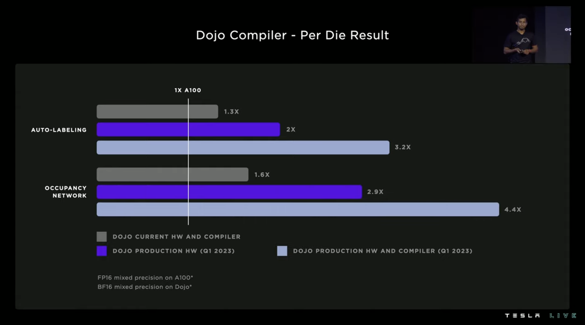
Using RESNET-50 as a test, A100 requires 192 batches under comparable FPS, while Dojo only requires 8 batches.In the more complex automatic annotation and environment-aware network, three groups of Dojo and NVIDIA A100 performance comparison were made. The gray group is the current hardware and compiler, which can exceed A100 by about 30\%. The Dojo hardware in 2023Q1 can exceed 190\%, and if the 2023Q1 compiler is added, it can exceed A100 by 340\%.
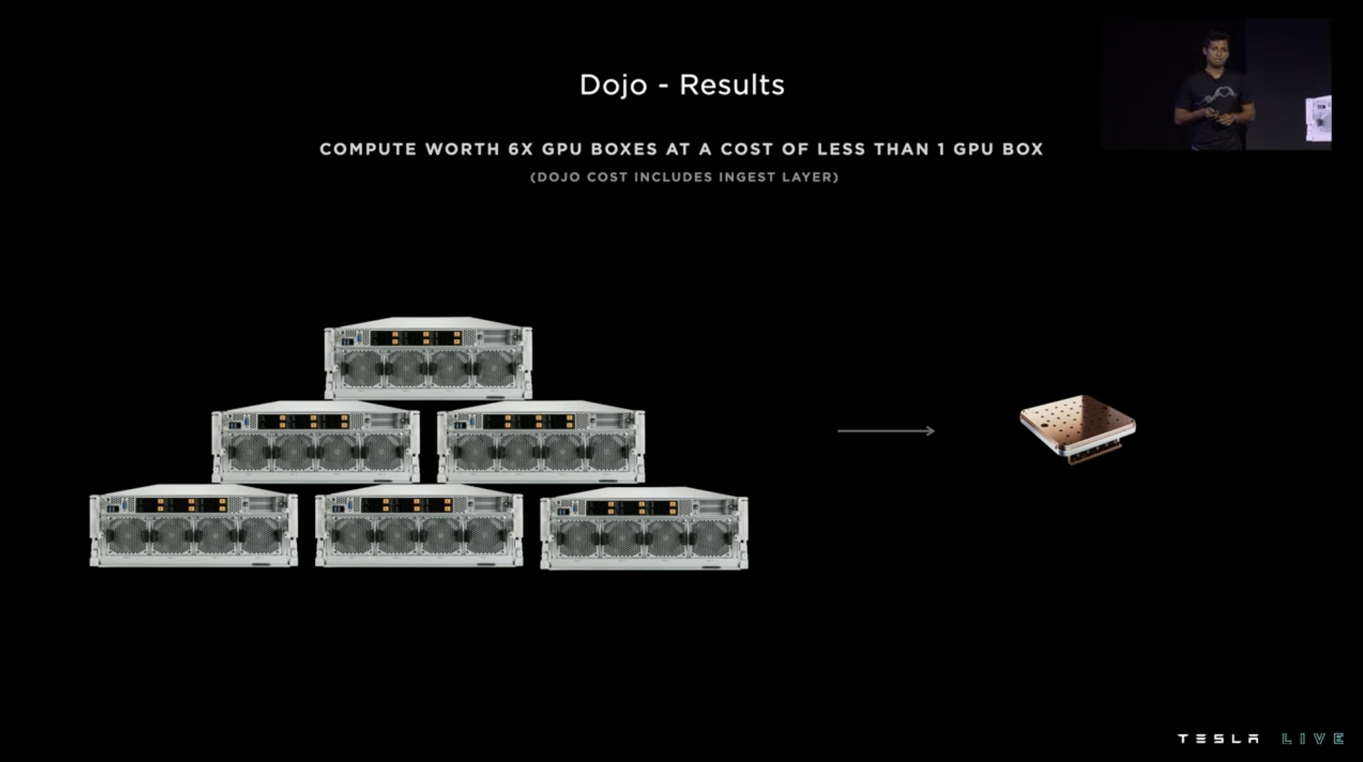
The computational performance of one Dojo training tile in the entire system can replace six GPU hosts, and the cost is even less than that of one GPU host.
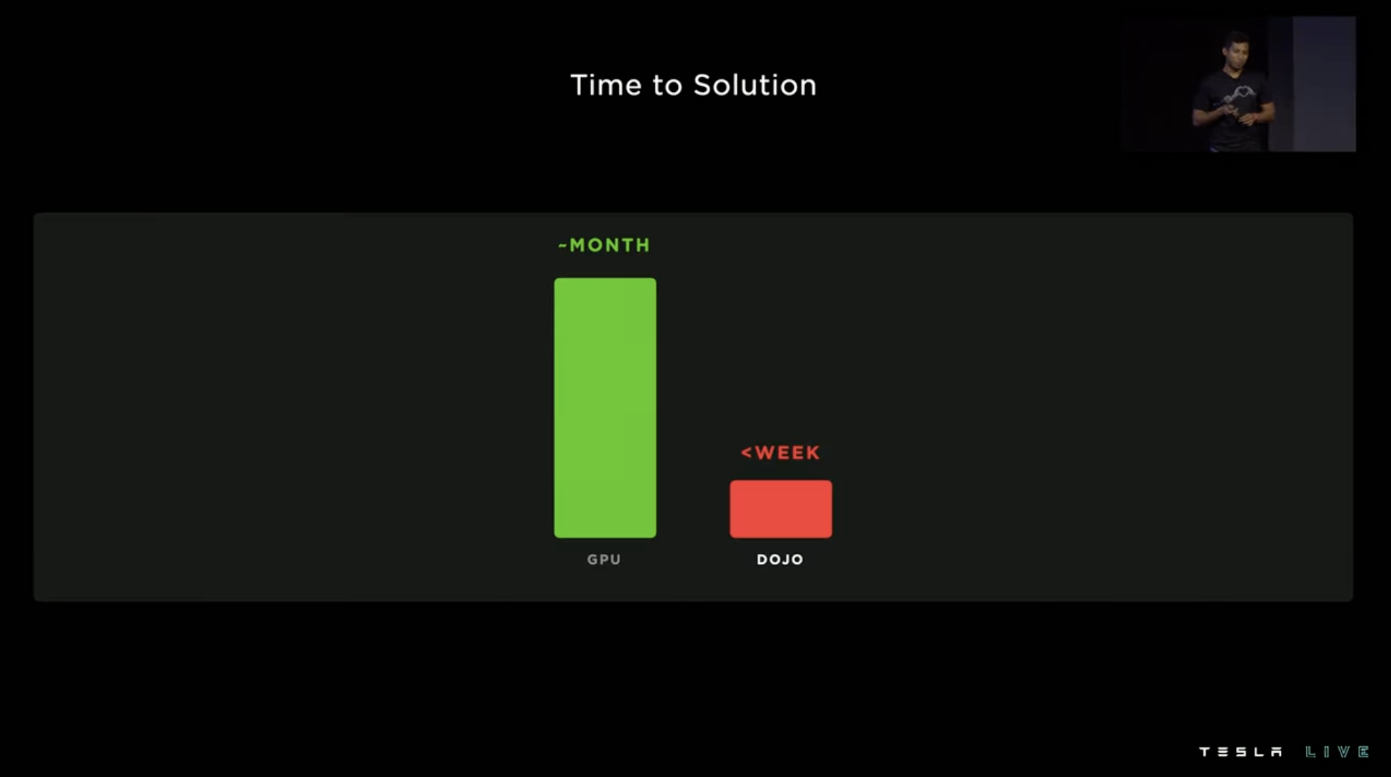
Previously, it took one month for training, but now it can be completed in one week with Dojo.
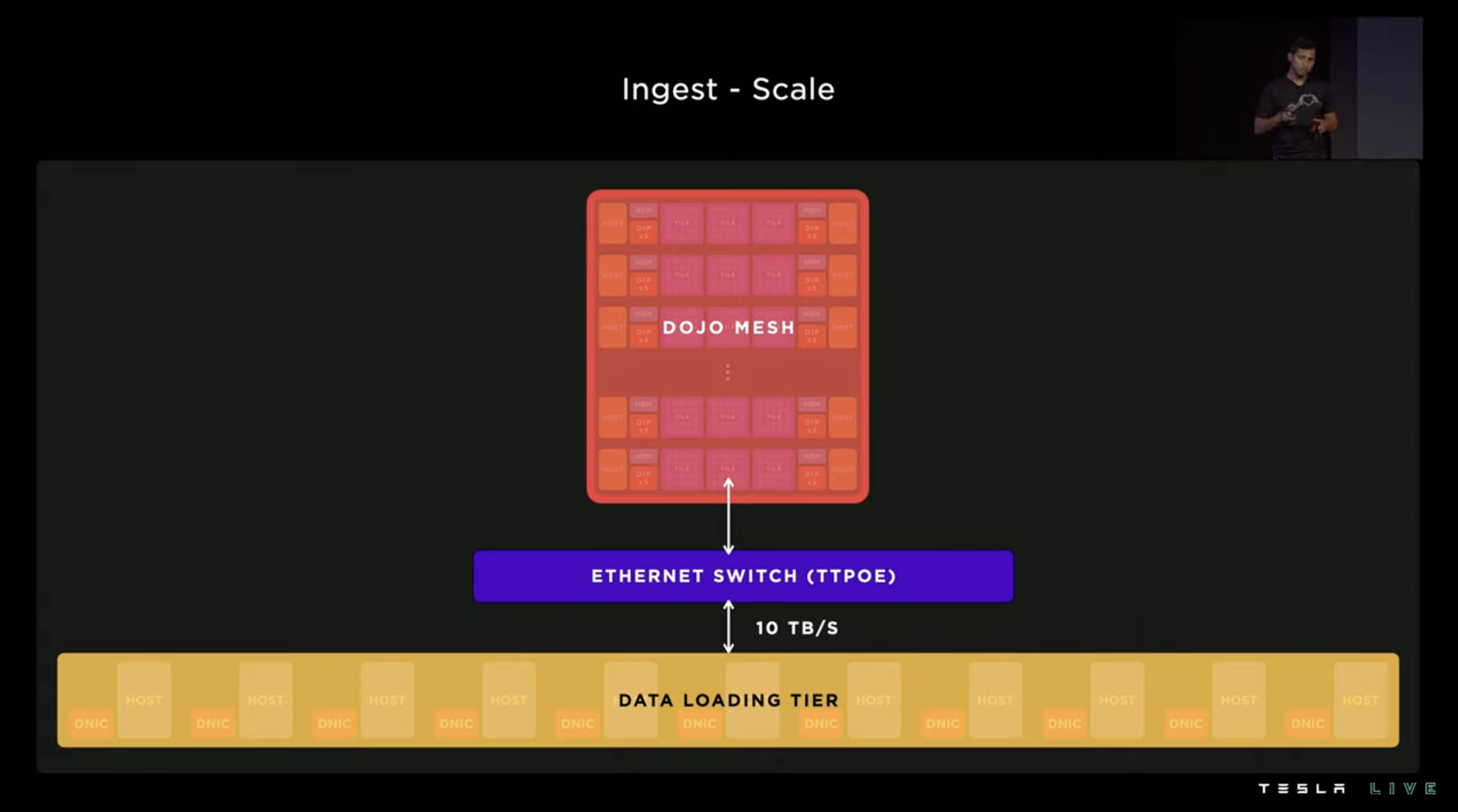
Tesla has optimized remote computing for pre/post-processing calls via data ingestion, so that the entire data download layer can be connected to the Dojo network, and the utilization rate of the system has increased from the initial 4\% to 97\%.


The computational performance of 72 GPU cabinet machines for automatic annotation tasks can now be replaced by only 4 Dojo cabinet machines. After 10 Dojo cabinet machines come online in 2023Q1, automatic annotation capability will reach 2.5 times the current level, and Tesla plans to build 7 ExaPODs in Palo Alto.
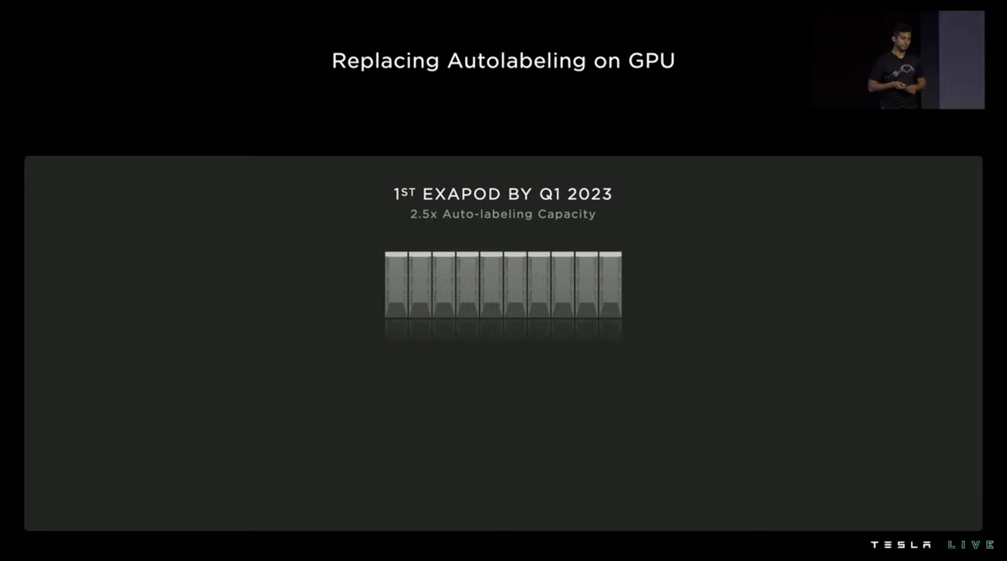

At the same time, Tesla will continue to develop new computing cluster hardware and continuously explore the system’s limit capabilities through software optimization. When the next generation hardware is unveiled, Tesla is confident that it will further improve its performance by 10 times.

In addition to using ExaPOD for their own use, Tesla will also provide cloud computing services to third parties, much like Amazon Web Services.
In conclusion,

Talent attraction is a key element in maintaining competitiveness for any technology company.
In the 2021 Tesla Impact Report, SpaceX and Tesla are the top two most desirable companies for engineering students.
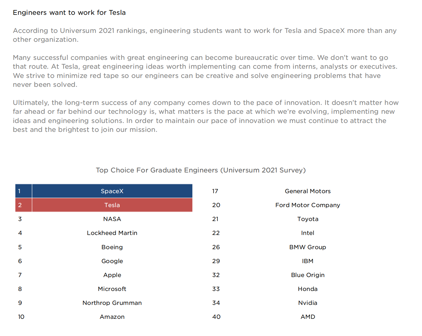
When discussing the purpose of holding AI Day, Musk said that the event is mainlyto recruit AI elites from all over the world to join Tesla. After the 2021 AI Day, the number of job applications Tesla received increased by** over 100 times** compared to the previous few weeks.
 At the same time, AI Day has also let more people understand the strength of Tesla, especially in AI. And it has to be said that, whether it is software or hardware, Tesla usually chooses the most difficult but highest long-term effective way in many things.
Some people call this approach long-termism, and some people think it is a reflection of the first principles. In my opinion, these understandings are all correct, but what I want to emphasize more is that not everyone can achieve high and low.
What really makes Tesla extremely difficult to be replicated by other companies is that no matter how difficult things are, as a start-up, it can always persist until the day of effectiveness.
It is said that without foresight, there will be immediate worries, but conversely, without immediate worries, there can be long-term vision.
Tesla has already passed the most difficult period of development. In today’s rapid development period, it has enough capital and strength to persist in long-termism in forward-looking business.
Taking the competition in China’s new energy market as an example, Model 3 and Model Y, which were released 6 years and 3 years ago respectively, still have a significant lead in sales compared to various newly released products in this market. On the one hand, it is because these two products have good competitiveness, and secondly, in the era where the new brand relies on products to win the market, Tesla has established a brand influence and supply chain advantages that its competitors cannot match.
If the issue related to survival is “important and urgent”, then there is no “important and urgent” issue on Tesla’s to-do list. At present, the “important” thing is to make plans and reserve for future development, and the “urgent” thing is to increase production capacity.
Therefore, when one autonomous brand after another is** burdened with survival crisis** and forced to fight a price war to seize the market, Tesla has the choice to make its own decision, either to remain motionless or to trade with lower price for larger quantity. Tesla’s model of taking small battery and low manufacturing cost routes, even if it lowers the price, is only a difference between earning more and earning less, far from companies that lose money by selling cars like some others.
For a company whose main revenue comes from the sales of cars, good sales volume is the foundation for all business development, such as the three major aspects of Optimus, FSD, and Dojo at this year’s AI Day.
The interpretation of FSD and Dojo can be summarized as Tesla has fully prepared vehicle-side software and cloud computing for pushing FSD Beta globally. Tesla is very likely to be the first company to achieve point-to-point intelligent driving on a single car relying on intelligent technology in multiple countries and regions. After that, the inflection point of FSD software revenue will also follow.But the ultimate goal is Optimus. Musk’s pessimistic prediction of global population growth has prompted him to search for solutions to social productivity shortages. Just as the “new energy bubble” on the Chinese market is difficult to imagine a few years ago, the competition has become so intense. Although we are not currently constrained by labor shortages, if the bottleneck of manufacturing capacity or profitability in the future becomes labor, Optimus has the opportunity to become a magic weapon for Tesla to cope with challenges.
It is not difficult to see that Tesla is accustomed to front-loading the crisis and always laying out for future development. Therefore, it does many things earlier than others, and it also does them better, enabling Tesla to have enough skills to cope with current competition at each stage, while its skill set continues to expand at an industry-leading pace. Most of the things Tesla is or will be tackling are long-term industry-level problems, and behind these problems is Tesla’s grand vision.
This is also the underlying logic of attracting talent for AI Day: to make a good ship, people’s thirst for exploring the sea must be aroused.
This article is a translation by ChatGPT of a Chinese report from 42HOW. If you have any questions about it, please email bd@42how.com.
