Author | PANGHUANG
Based on different brake actuators, Brake-By-Wire system can be divided into Electro-Hydraulic Brake (EHB) and Electro-Mechanical Brake (EMB). EHB, which is based on traditional hydraulic brake system and uses electronic devices to replace some mechanical functions, uses brake fluid as the power transmission medium and has hydraulic backup braking system. It is currently the mainstream technology. EHB can be divided into Two-box and One-box according to the level of integration.
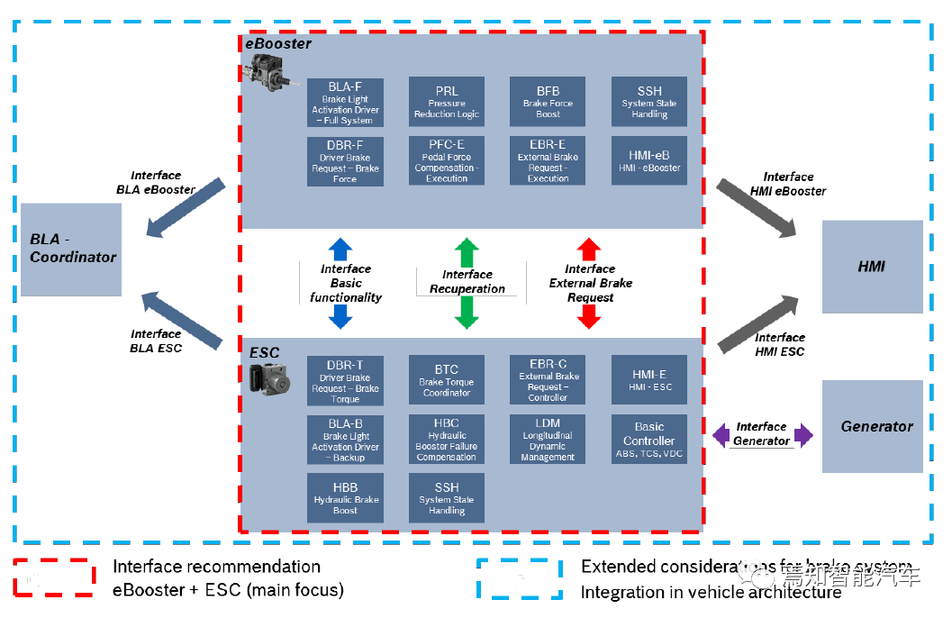
With the expansion of the new energy vehicle market, “eBooster+ ESC” combination has become the most popular Two-box solution in the current market. In addition to achieving basic brake assist and stability control functions, this solution can also coordinate and ensure consistent pedal feel during the switch between electric and hydraulic braking while achieving brake energy recovery. In addition, with the popularization of high-level advanced driver assistance systems and automatic parking systems, “eBooster+ ESC” also plays a role in achieving brake redundancy.
In the previous issue, we explained the system architecture and degradation strategy of the “eBooster+ ESC” combination. In this issue, we will introduce the implementation of the basic braking function of this combination.
- Driver brake control
- External ECU brake control
- Brake light control
Driver brake control
To achieve the driver brake assist function, eBooster needs to detect the driver’s brake intention correctly first. The pedal travel sensor installed at the eBooster push rod monitors the depth of the driver’s pedal depression, and feeds it back to the DBR-F (Driver Brake Request-Brake Force) module of eBooster for driver intention determination.
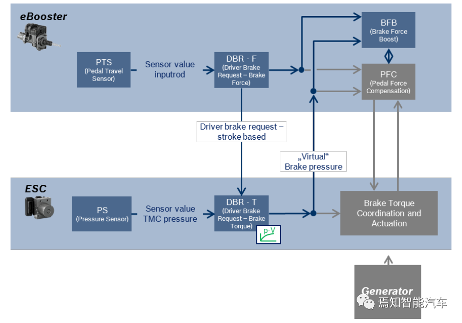
After determining the driver’s braking intention, eBooster does not provide direct assistance, but feedbacks the driver’s braking intention through network communication to ESC, which allocates hydraulic braking force and motor braking force.As a vehicle stability control system, the main purpose of ESC to distribute braking force is to ensure that the distribution does not pose a risk of vehicle instability, such as when the driver encounters a hard accelerator pedal condition that causes the wheels to lock up, the ESC system will stop requesting braking force from the drive motor and instead stabilize the vehicle by adjusting the wheel cylinder hydraulic pressure, while activating ABS.
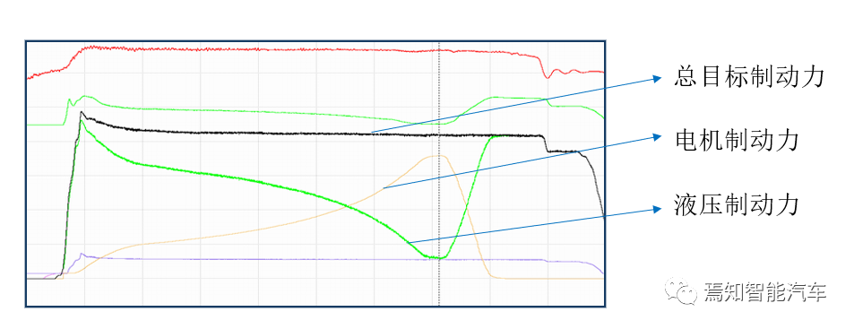
Secondly, the distribution of braking force by ESC can achieve energy recovery during the braking process. The energy recovery function has emerged in sync with the popularity of new energy vehicles. With the role of energy recovery, in addition to the friction braking generated by hydraulic pressure during the vehicle braking process, the cooperation of high-voltage batteries and drive motors produces negative torque, providing part of the braking force, and the negative torque produces reverse current to charge the high-voltage battery. Finally, part of the vehicle’s kinetic energy is converted into chemical energy and stored in the high-voltage battery during braking, which is used for the next vehicle drive, thereby achieving energy recovery and reducing energy consumption and emissions.
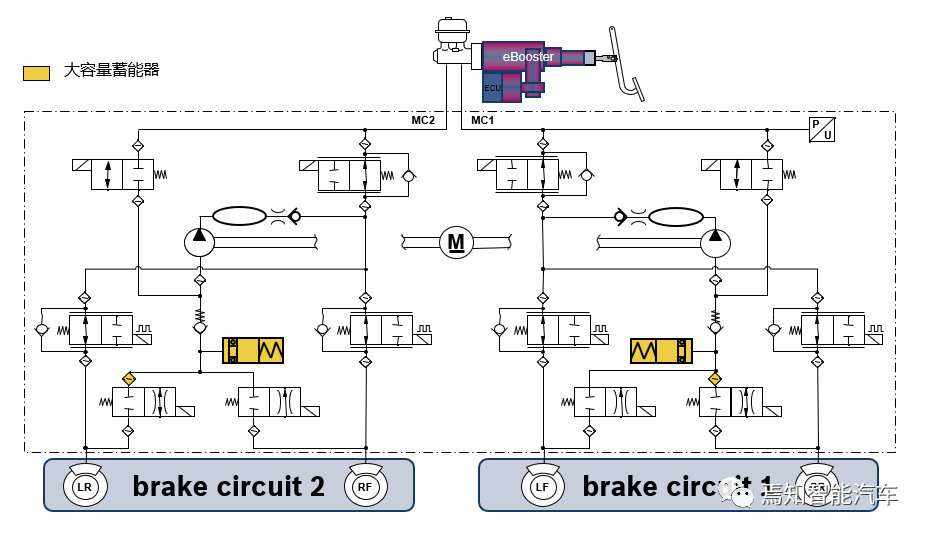
To achieve brake force distribution, ESC’s hardware first needs to disconnect the “direct link” between the master cylinder brake fluid and the wheel cylinder brake fluid, which is achieved by ESC’s large-capacity accumulator and control of the wheel-end solenoid valve. With the support of the large-capacity accumulator, when the driver steps on the brake pedal, the eBooster controls the master cylinder hydraulic pressure to enter the wheel cylinder to produce braking force. At the same time, the braking force of the drive motor gradually increases as the depth of the brake pedal increases. During this process, the brake fluid from the master cylinder will not flow directly into the wheel cylinder, but will be temporarily stored in the accumulator. The brake fluid in the accumulator does not produce braking force, thereby achieving dynamic coordinated control of the braking force of the drive motor and hydraulic brake force during the braking process.
However, the “separation” of the master cylinder brake fluid and the wheel cylinder brake fluid caused by ESC’s dynamic brake force distribution process can lead to changes in the brake pedal feel for the driver. The PFC (Pedal Force Compensation) module of eBooster can ensure consistent pedal feel. The core principle is that during the driver’s braking process, the eBooster controls the size of the assist force (as shown in the figure below), ensuring that the feedback force applied to the driver’s foot is constant at the same depth of pedal depression. This enables drivers to feel the same pedal force irrespective of whether motor or hydraulic braking is being used, thereby achieving pedal feel consistency and providing the most comfortable experience for the driver.

In the above figure, the spring force Fsprings is constant. In order to achieve a constant pedal force Fpedal at a certain pedal depth, the PFC module needs to know the size of the braking force Fhydraulic that can be generated by the current hydraulic energy, so as to adjust the appropriate boost force Fboost. However, due to the influence of the energy accumulator liquid control and the wheel-side electromagnetic valve control in the brake force distribution process, the main cylinder pressure value collected by the master cylinder pressure sensor in the ESC system cannot correspond to the truly generated hydraulic braking force. Therefore, ESC needs to send a “virtual” main cylinder pressure value to the PFC module of eBooster to determine the size of Fhydraulic. The virtual main cylinder pressure value is obtained by looking up the pre-calibrated pv curve in the DBR-T (Driver Brake Request-Brake Torque) module of the ESC and is feedback to the PFC module of eBooster through communication to determine the boost force size required to achieve the desired pedal feel.
External ECU Brake Control
Because the dynamic response speed of eBooster’s pressure build-up is faster than that of ESC’s active pressure build-up, and eBooster’s NVH performance is better, eBooster is the main execution mechanism for brake system when receiving external brake requests from external ECUs (such as ADAS ECUs). This can also reduce the load of active pressure build-up throughout the life of the ESC system.
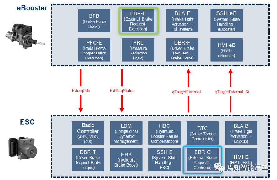
In the ESC system, the EBR-C (External Brake Request-Controller) module is responsible for receiving brake requests from external ECUs and converts the brake request into a target master cylinder pressure value and sends it to the EBR-E (External Brake Request-Execution) module in eBooster through the communication network, and then eBooster calculates the target boost force value to implement the brake request.
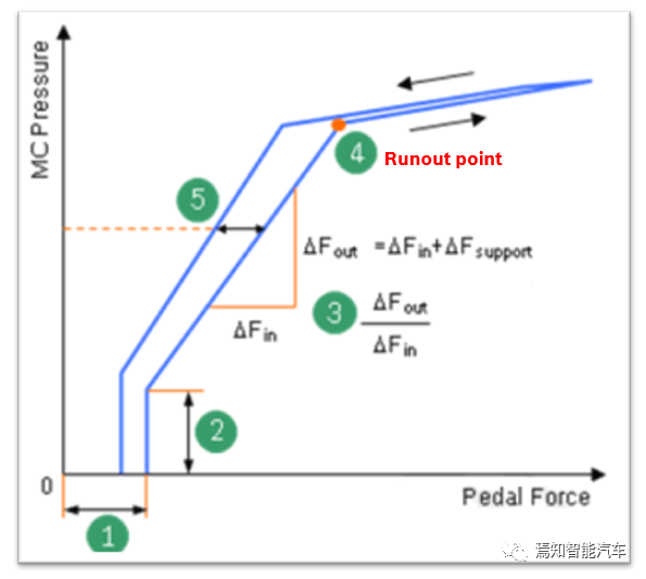
During this process, eBooster also provides real-time feedback of the actual output pressure value to ESC. For example, when the boost capability of eBooster significantly decreases after reaching the Runout point (see the figure below), ESC provides brake compensation through active pressure build-up.

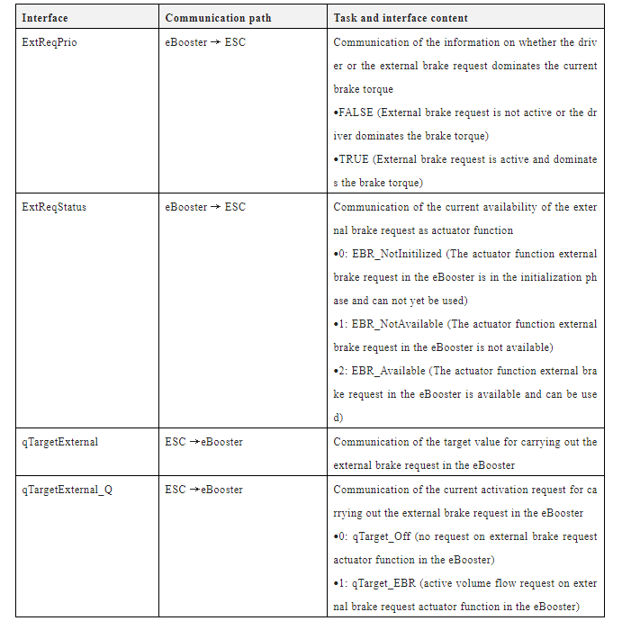
The following table summarizes the main interaction signals and purposes between ESC and eBooster when external ECU braking is implemented.
Brake Light Control
The strategy of brake light control is related to the degraded state of the eBooster system.
When the eBooster is in full function, the brake light is controlled by the eBooster system according to the state of the driver’s pedal. At this time, ESC only requests the brake light to be turned on when the stability function or the auxiliary function that does not depend on the driver’s braking is activated.
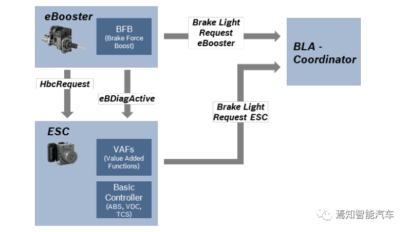
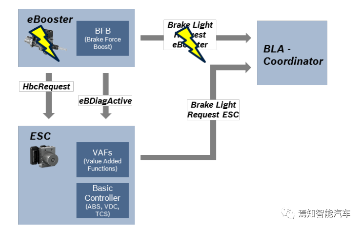
When the eBooster assist function fails, the eBooster requests the activation of the HBC function, and the driver’s braking request is implemented by ESC actively building pressure. At this time, the brake lights in all operating conditions are completely controlled by ESC, including the driver’s braking condition, stability function and auxiliary function actively building pressure condition.
This article is a translation by ChatGPT of a Chinese report from 42HOW. If you have any questions about it, please email bd@42how.com.
