Author: Zhu Yulong
With the continuous development of automotive intelligence, smart driving and the high-precision positioning technology it requires are gradually entering the public eye.
If high-precision maps draw the invisible tracks for smart car driving, then high-precision positioning technology is the “best partner” of the former, supporting cars to safely drive on the tracks – after matching the high-precision position information with the map, the navigation function is realized, and time synchronization with the whole perception system is achieved, providing the basic spatiotemporal information for smart driving.
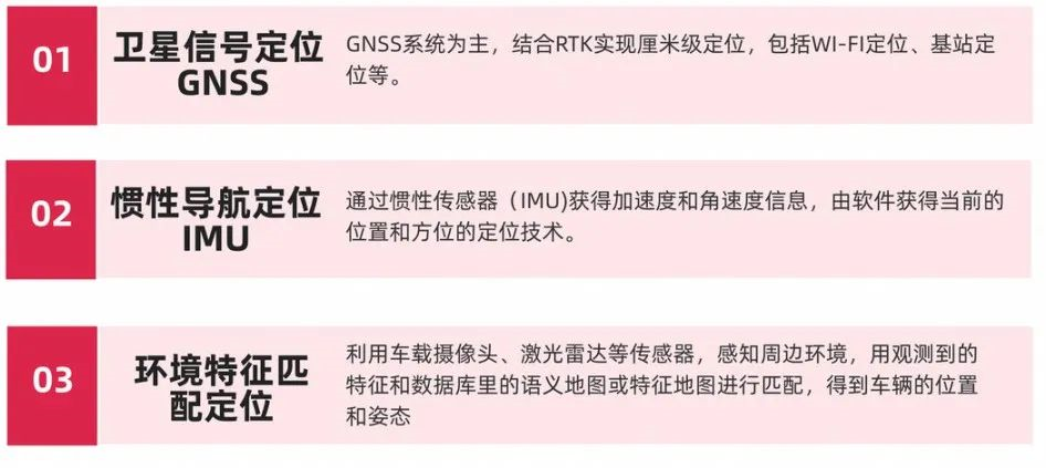
According to the hardware used, high-precision positioning technology can be divided into three categories: satellite navigation (GNSS), inertial navigation (INS/IMU), and environmental feature matching positioning.
- Satellite signal positioning
Mainly based on the GNSS system, combined with RTK to achieve centimeter-level positioning.
- Inertial navigation positioning
Self-navigation positioning that does not rely on any external information, relying on inertial sensors (IMU) to obtain acceleration and angular velocity information, and then calculate the current position and orientation from it. It was first used in the military industry. Here, we further divide inertial navigation systems into two categories: platform-type inertial navigation systems and strapdown inertial navigation systems. Strapdown inertial navigation systems (SINS) are developed on the basis of platform-type inertial navigation systems. They are simple in structure, have high reliability, small volume, light weight, and low cost. With the development of high-speed and large-capacity digital computer technology and high-precision gyro technology, strapdown navigation systems have gradually replaced platform-type systems in low-cost and short-term high-precision navigation.
- Environmental feature matching positioning
By using on-board cameras, LiDAR, and other sensors to perceive the surrounding environment, match the observed features with the feature map in the database to obtain the vehicle’s position and posture.
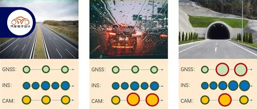
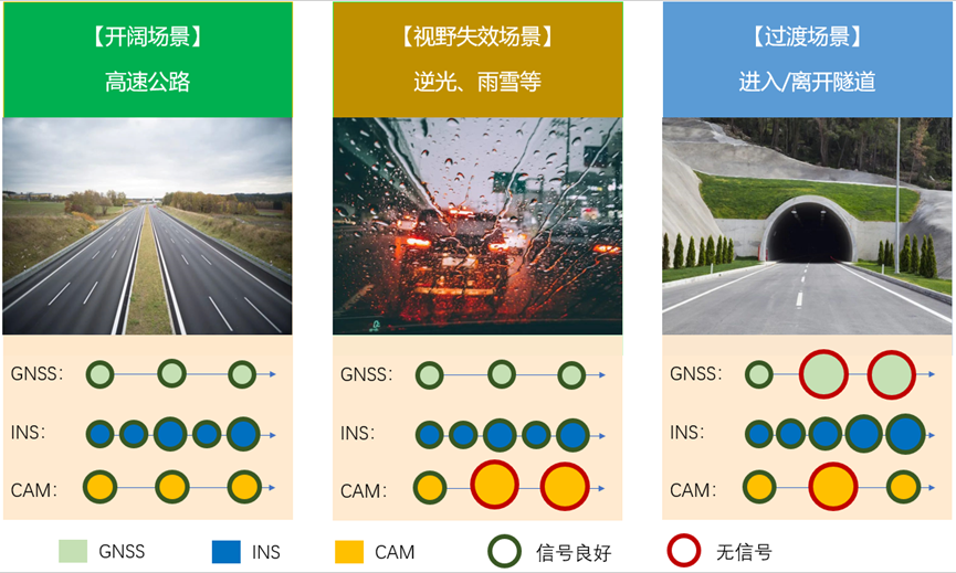
To achieve high-precision positioning for smart driving, the fusion of these three categories of technology is required. The trend of technology is multi-element fusion and heterogeneous redundancy. For the observation of any physical quantity, multiple sensors are used to complement each other.
With the gradual deepening of cognition, in the development of automatic assisted driving systems, the combination of satellite signal positioning and inertial navigation positioning (satellite-inertial integrations), due to the complementary information of the two, is gradually considered to be able to better exert the system’s advantages. Especially, the combination of low-cost strapdown inertial navigation system and satellite navigation system has been one of the hot research topics in navigation both at home and abroad, and is expected to become the main positioning technology solution in the future.
The advantages of satellite-inertial integrations are as follows:
-
High positioning accuracy.GNSS and IMU can achieve centimeter-level positioning separately. IMU can combine vehicle wheel speed, steering wheel angle, and other sensor information to further improve positioning accuracy.
-
Versatile
GNSS provides accurate absolute positioning in all weather conditions and at all times. In areas where satellite signals are lost, such as tunnels or underground parking lots, IMU can deduce the vehicle’s trajectory based on road information sensed before the failure, ensuring safe driving.
- Improved Reliability
IMU can validate the consistency of GNSS positioning and filter and correct GNSS data that cannot be self-consistent.
There are three coupling modes in GNSS/INS integration: loose coupling, tight coupling, and deep coupling. From the naming perspective, there is a common misunderstanding that the coupling degree and positioning accuracy of these three modes are from low to high. Today’s article reveals the connotations of these concepts and discusses future development trends.
“X Coupling” and “Decoupling”
Standard Coupling Model (Loose Coupling Model)
Here, we first start with the Standard Fusion Model for GNSS/INS (SFM), which is the technical basis and prerequisite for tight/deep coupling.
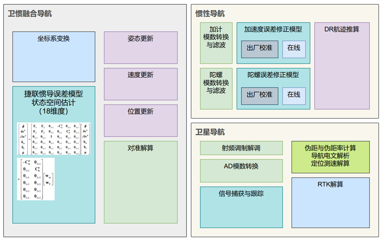
SFM is a mathematical model for classical GNSS/INS integration system, and it is also the “common foundation” of all derived algorithm branches. Its commonality accounts for more than 95% of the entire GNSS/INS fusion technology field. As later generations developed technical branches in specific areas, to highlight the innovation of new methods, the standard coupling model (loose coupling) has been “devalued” to a “loose coupling model.”
-
The advantages of SFM are mainly that it is easy to implement in engineering, has low computational complexity for the fusion system, and can meet the system’s design requirements with high real-time performance. The two systems still operate independently, so even if one system fails, the fusion system can continue to operate, ensuring the continuity of measurements.
-
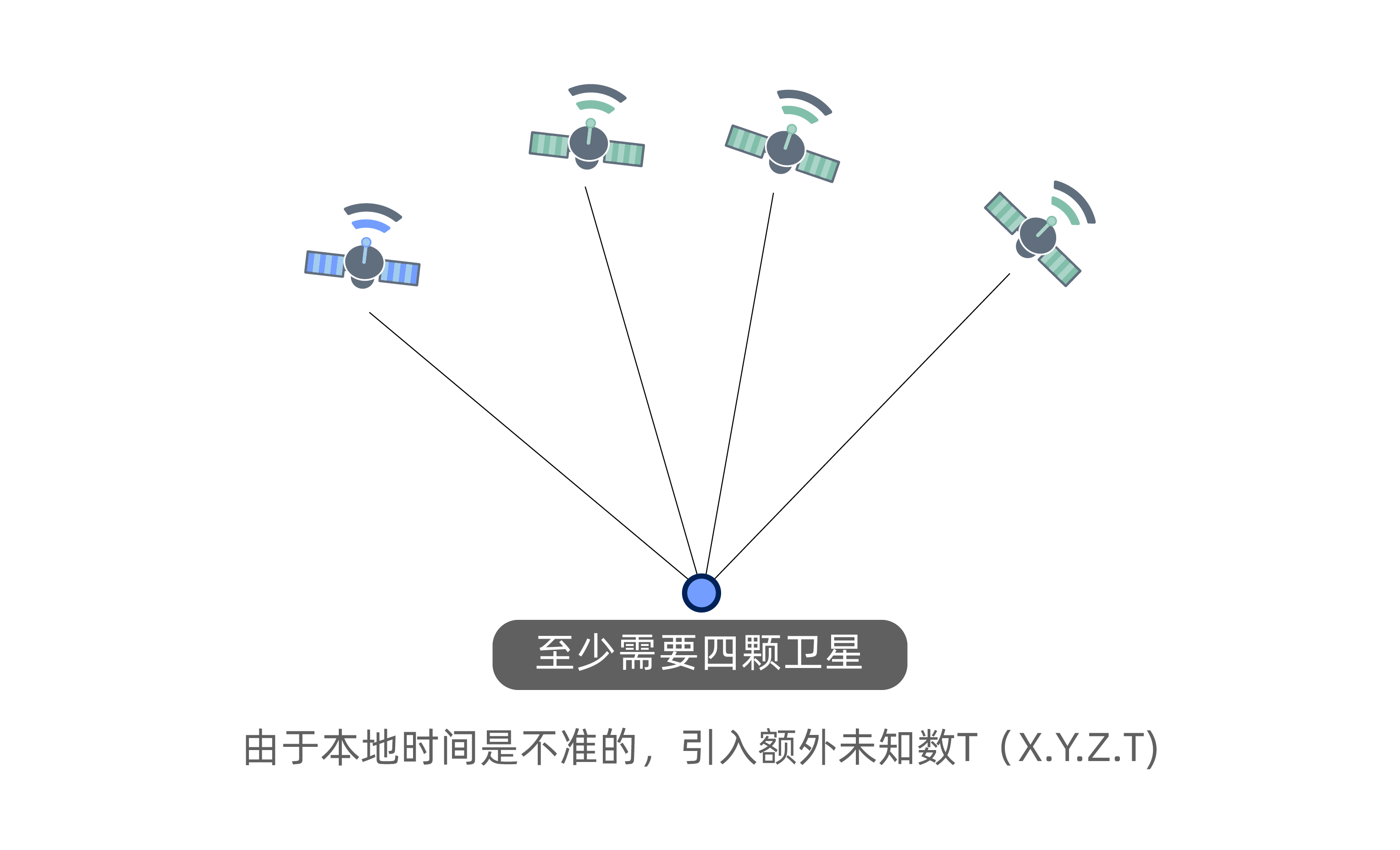
The disadvantage of SFM is that this method requires no fewer than four visible satellites, and the GNSS module cannot be positioned in this case.
Here, GNSS/RTK positioning results and IMU raw data are used for fusion. The GNSS and INS systems calculate the carrier’s attitude and motion information separately (satellite output position and velocity, inertial output position, velocity, and attitude), and the obtained results are imported into the filter for further calculation to estimate the INS error situation.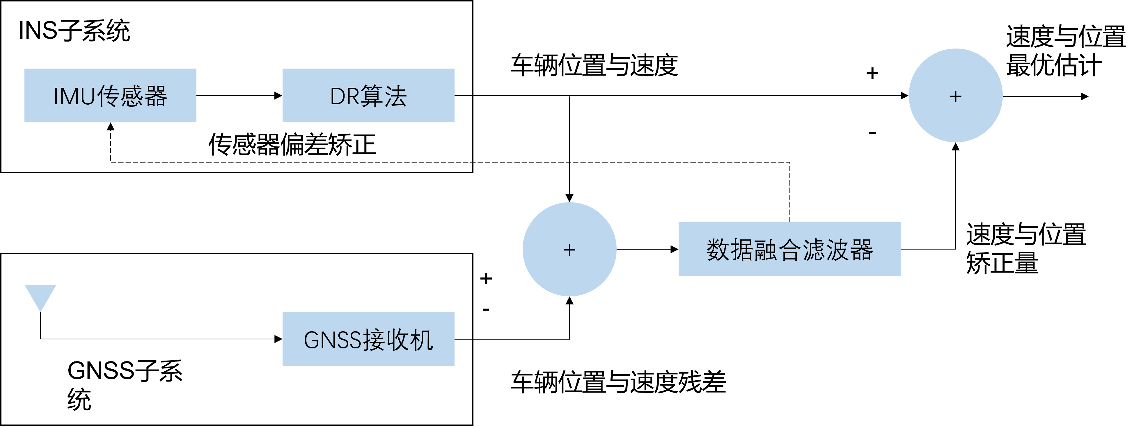
Tight Coupling
Having discussed “loose coupling,” its counterpart is “tight coupling.” The tightly coupled navigation system is basically the same as the standard coupled navigation system in terms of functionality.
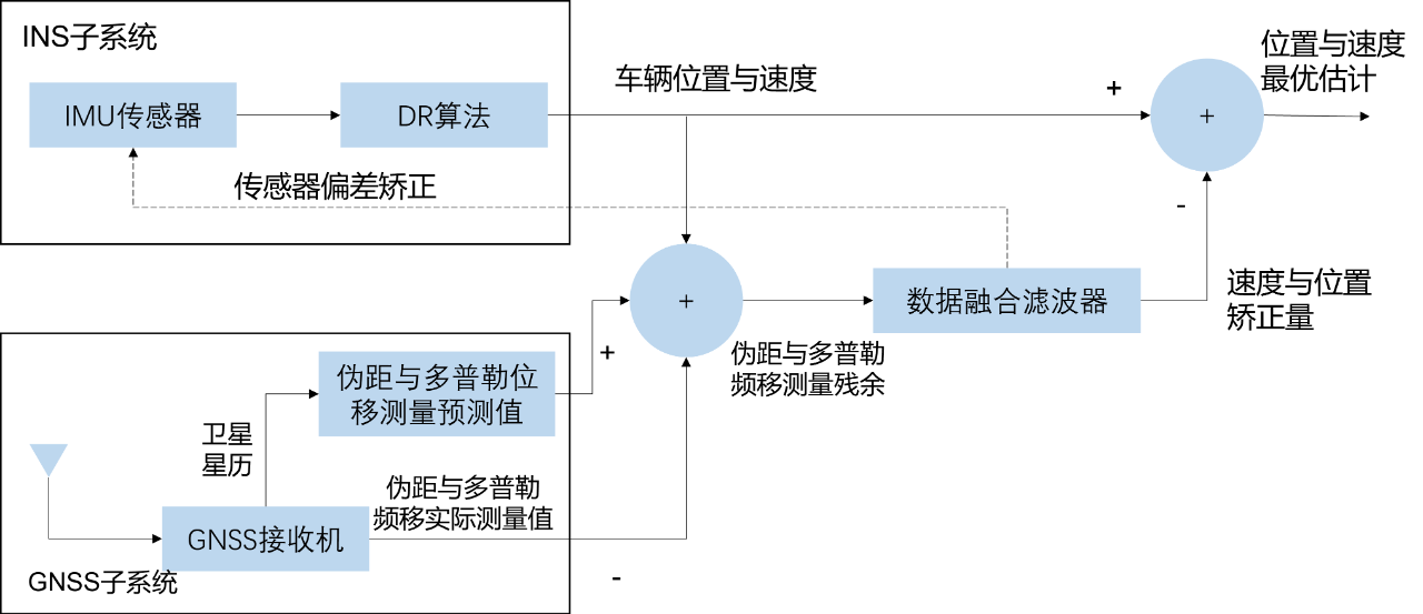
Unlike the standard coupled (SFM) navigation system, the GNSS receiver outputs the raw sampling data, such as pseudorange and Doppler shift. By subtracting the predicted pseudorange and Doppler shift obtained by the INS system from the pseudorange and Doppler shift obtained by the GNSS receiver, the measurement residuals of the pseudorange and Doppler shift can be obtained as the observation quantity of the data fusion filter. After the observation quantity is input into the data fusion filter, just like the standard coupling (SFM) system, INS calculation errors and sensor biases can be obtained to complete the alignment of the INS system and obtain the optimal estimation of position and velocity.
The most typical application of tight coupling is in the military environment, especially in the case of encountering a certain degree of electronic countermeasures, a small number of satellites (<4), and no differential correction (no RTK); at the same time, it is a relatively high dynamic environment such as a flying body cruising at a speed of 200 meters/second (720 kilometers/hour).
Compared with loose coupling technology, the advantages of tight coupling are mainly as follows:
-
Tight coupling can better maintain lock-on to satellites in the presence of interference. However, except for the signal-to-noise ratio, this advantage is difficult to quantify.
-
In the case of less than 4 visible satellites, it can also work normally in a short time, but the positioning accuracy will drop sharply.
Deep Coupling
Deep coupling is used in high dynamic and RF interference environments, without differential correction (no RTK). At this time, neither the GNSS/INS standard coupling (SFM) system nor the GNSS/INS tight coupling system can work properly, such as missiles, rockets, and other non-human-carrying equipment.
Here, the Jet Propulsion Laboratory (JPL) in the United States defines the “high dynamic test environment” as the carrier withstands a high acceleration of up to 70g/s continuously for 1 second. Or, the dynamic scene is that the carrier withstands a positive acceleration of 100g/s continuously for 0.5 seconds, and then after a 2-second interval, it withstands a negative acceleration of 100g/s continuously for 0.5 seconds. Generally, only the re-entry phase of ballistic missiles can reach this level, and the dynamics of the cruise missiles that require higher navigation accuracy are generally lower than these two test scenarios.In actual vehicle applications, when the zero to one hundred km/h acceleration time reaches about 4 seconds, the acceleration is 0.7g; and when it reaches 3.8 seconds, the acceleration is 0.74g. In fact, deep coupling technology was developed to compensate for the insufficient positioning performance of non-passenger flying objects under extreme scenarios.
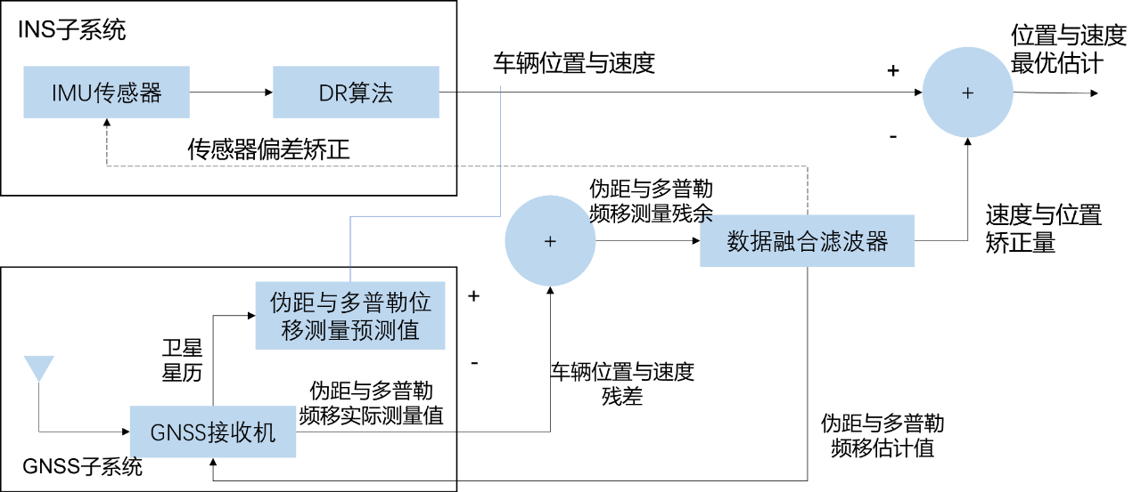
Compared to tightly coupled navigation systems, deep coupling navigation systems add INS units to assist GNSS receivers. By using INS units combined with ephemeris information, the estimation of pseudorange and carrier Doppler frequency shift can be achieved, and the estimation results can assist the receiver’s acquisition and tracking loops. In fact, this scenario is mainly used in military navigation. Remote precision guidance launch tasks require fast flying over the ionosphere, with dynamic range requirements up to 40g or even higher. The Doppler frequency shift between satellites and carriers caused by high dynamics will seriously affect the GNSS signal tracking. Under high dynamic conditions, the ±50~100kHz Doppler frequency shift caused by high speed rate will cause the normal receiver carrier tracking loop to lose lock, and cannot demodulate the navigation message; the high dynamic range Doppler frequency jitter requires the widening of the loop bandwidth and the reduction of the working SNR, resulting in reduced loop tracking accuracy; it can also cause dynamic time delay of the pseudo-random code, causing the code loop to lose lock.
-
The advantage of the deep coupling model is that it can improve the stability of the tracking loop under high dynamic conditions and improve the receiver’s dynamics, thereby improving the sensitivity of the receiver’s tracking loop, even in a strong RF interference environment.
-
The disadvantage of it is that because the coupling between the two systems is very deep, when the two systems are disconnected, the GNSS receiver cannot complete the positioning and speed measurement work, and it cannot continue to track the satellite signal. If there is no corresponding switching method to control it, it will cause the satellite signal to lose lock. Moreover, the switching design of the deep coupling tracking method should avoid the state switching deadlock of the INS assistance (to prevent positive feedback).
However, as a high-precision positioning solution, the deep coupling model has a problem: it is not taken into account in military and aerospace fields, and the cost is not a concern. The more high-end the better. But in cars, the solution of rising single-vehicle cost due to the greater computing power demand is not feasible. Especially in the civilian domain that is not the military industry, there is no mature SOC chip under this high demand, and an FPGA+DSP solution is usually used as a hardware solution.
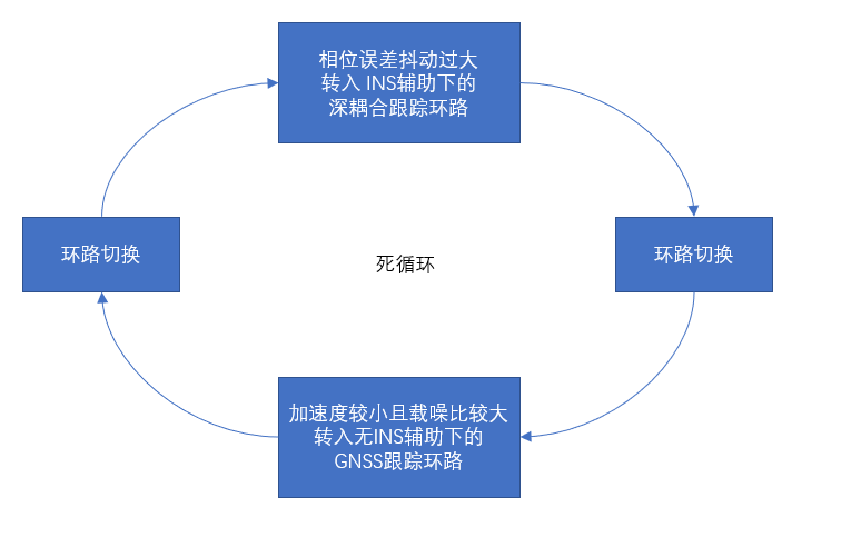 The chip needs to be supported by shipping quantity. Deep coupling is often considered beneficial, but due to the absence of a mature SOC chip, all publicly available hardware solutions in the automotive field currently use FPGA+DSP solutions as the hardware solution.
The main components commonly used in deep coupling are:
- TI DSP 674 series
- Intel/Altera FPGA (non-automotive grade)
- Xilinx XA series (automotive grade), XA7A12T – the cost of similar chips is a few hundred dollars, and with a lead time of over 52 weeks, even if not considering price, there may be room for discussion in terms of “supply chain security”.
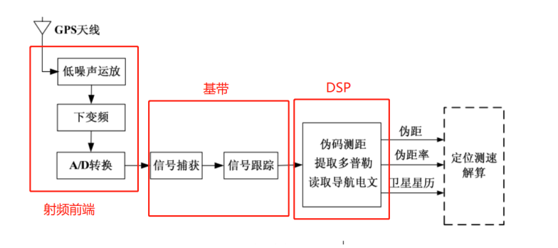
The prerequisite for large-scale application of the automotive sector is that the system must be mature and low-cost. Obviously, in practical applications, the quality of the solution is not a progression from standard coupling to tight coupling to deep coupling, but depends on the reliability of handling operating conditions.
Decoupling
For combined navigation, the most difficult “lost star conditions” (such as serious shielding or underground conditions) on urban roads are the focus of concern in the engineering practice of autonomous driving technology. How should the fusion algorithm handle this?
The answer is: Dead Reckoning. That is, using the IMU to obtain the high-precision three-dimensional acceleration and angular velocity information of the carrier, and obtain the carrier’s three-dimensional motion trajectory and attitude through integration. It is worth noting that, in such operating conditions, there is no difference between all of the above satellite-inertial fusion technologies, because the GNSS system has already failed (or lost its lane-level positioning due to very low precision), and the satellite-inertial system enters the “pure inertial calculation” working mode. The system accuracy at this time depends 100% on the IMU accuracy level. This may be why the author of “Strapdown Inertial Navigation Technology” David H. Titterton believes that “other advantages of different fusion technologies are difficult to quantify except for their interference signal ratio.”## The “New Trend” of Fusion Technology
In the case of severe satellite obstruction or complete loss of signal, the various couplings between the inertial and satellite navigation systems are ineffective. The advanced engineering practice in the industry is to decouple as quickly as possible and enter the Inertial Calculation Mode (DR: Dead Reckoning) based on IMU and chassis information fusion. At the same time, in recent years, the use of IMU + Vision-based slam/VIO technology for such conditions has become a research hotspot. Looking at the trend of academic literature in the past decade, well-known universities at home and abroad (such as the University of Calgary in Canada) have launched a lot of explorations on the route of the fusion technology of inertial + vision (or Lidar) + chassis information fusion technology (such as VSlam/VIO technology). Stay tuned for further sharing of more advanced research.
Looking at the broad category of “positioning” technology in automated driving, with the rapid development of sensor technology, performance improvement, and cost optimization by an “order of magnitude,” automated driving technology, as a branch of artificial intelligence technology, is also catching up with the mainstream technology route and slowly getting rid of the constraints of high prices on the technology route selection. After experiencing three stages from the early 21st century to today:
- Phase 1: Laboratory level multi-sensor fusion
- Phase 2: Technology introduction enters mass production and begins to control costs by adopting a large number of “clipping” schemes
- Phase 3: The technological explosion dividend restarts the multi-sensor fusion technology route for “mass production”
From the perspective of automated driving “positioning” technology, it is difficult to ensure navigation accuracy in the case of long-term satellite loss of lock of the widely used inertial satellite navigation system. In the absence of other sensor assistance, using the vehicle model to assist navigation has become a new direction of vehicle navigation research, mainly: direction of kinematic and dynamic model assisted vehicle navigation technology and direction of multi-source fusion technology.
Summary: Tight and deep coupling as a refinement of the “classical combined navigation” technology can optimize the satellite tracking performance of the GNSS system for high-dynamic and non-passenger scenarios and can make some “unqualified” working conditions available (reaching 60 points). However, the hardware solutions required for deep coupling have not yet entered the massive scale stage, and the comprehensive performance and cost-effectiveness need to be further verified.
Currently, the development trend of high-precision combined navigation at the “lane level” has shifted from the classical satellite/inertial combination to the direction of vehicle kinematic model and multi-source fusion technology route.
Reference*Titterton, David, John L. Weston, and John Weston. Strapdown inertial navigation technology. Vol. 17. IET, 2004.
*Lü Xinzhi. GNSS Receiver and Inertial Navigation Deep Integration Technology Research. MS thesis. University of Electronic Science and Technology of China, 2013.
*Ji Feng. Simulation and key technology research of inertial/satellite tight coupling navigation system [D]. Nanjing University of Aeronautics and Astronautics, 2009.
*Wang Peng. Accuracy analysis and optimization technology of INS/GNSS deep integration system for high dynamic aircraft [D]. University of Electronic Science and Technology of China, 2015.
*Huang Shaojie. Research and hardware implementation of GPS high dynamic receiver [D]. Beijing University of Posts and Telecommunications, 2009.
*Dissanayake, Gamini, et al. “The aiding of a low-cost strapdown inertial measurement unit using vehicle model constraints for land vehicle applications.” IEEE transactions on robotics and automation 17.5 (2001): 731-747.
*Wang J. H., and Yang Gao. “Land vehicle dynamics-aided inertial navigation.” IEEE Transactions on Aerospace and Electronic Systems 46.4 (2010): 1638-1653.
This article is a translation by ChatGPT of a Chinese report from 42HOW. If you have any questions about it, please email bd@42how.com.
