Author | Banjiang
Smart Chassis Series (1) | Yesterday, Today and Tomorrow of Smart Chassis
Smart Chassis Technology (2) | Overview of Automotive Brake System Development
Smart Chassis Technology (3) | Starting from Vacuum Booster
Smart Chassis Technology (4) | Introduction to Wire-controlled Braking eBooster
Smart Chassis Technology (5) | Evolution of Chassis Electronic Stability Control System: ABS
Smart Chassis Technology (6) | Evolution of Chassis Electronic Stability Control System: TCS
With the development of the automotive industry, cars are becoming heavier and faster, which not only imposes higher requirements on the basic braking capacity of the car, but also presents greater challenges to the stability of the vehicle. According to research on automobile safety, approximately 10% of traffic accidents are caused by vehicles deviating from the predetermined trajectory or spinning out during braking. It is well known that improving the braking performance of the chassis is an important measure to reduce traffic accidents, and actively intervening in braking is the key to improving the braking performance.
Although the theoretical research on actively intervening in the braking system to improve vehicle stability started a long time ago, the practical implementation depends on the right timing and circumstances in technology. The widespread application of hydraulic braking replacing traditional mechanical braking, as well as the development of electromechanical technology, provided the technical basis for achieving active braking intervention and even active intervention in driving and suspension. From the beginning of the Anti-lock Brake System (ABS) to today’s Vehicle Dynamic Control (VDC), the electronic stability control system of the chassis has begun a splendid evolution.
However, the evolution of the electronic stability control system of the chassis has not stopped. The new E/E architecture of the smart chassis has brought new optimization directions for the electronic stability control system of the chassis, such as the coordinated operation of various subsystems under the control of the chassis domain controller, which can achieve faster stability control. The topic of intelligent chassis and electronic stability control system is becoming a hot research topic for mainstream OEMs and suppliers.Against this backdrop, the evolution of electronic stability system and the new direction brought by intelligent chassis to electronic stability system will be explored based on the following architecture in the following issues.
This article will introduce part3.
- Part1: ABS: Operating principle of Anti-lock Braking System
- Part2: TCS: Operating principle of Traction Control System
- Part3: VDC: Turning ESP into a Revolutionary Product
- Part4: Outlook: Development of intelligent chassis and electronic stability system
Function of VDC: Turning ESP into a Revolutionary Product
Since ABS only works during braking and TCS only works during driving, the integration of ABS/TCS can only solve the longitudinal stability problem of the vehicle, and cannot solve the lateral stability problem caused by extreme working conditions such as driving steering, brake steering, and high-speed steering.
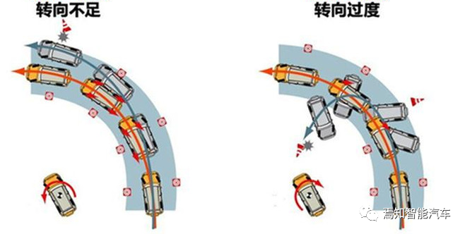
In summary, there are two typical dynamic problems of the vehicle caused by improper steering:
- Insufficient steering
- Excessive steering
When insufficient steering occurs, the lateral yaw velocity is too small, causing the front axle of the vehicle to slide towards the outside of the bend; when excessive steering occurs, the lateral yaw velocity is too large, causing the rear axle of the vehicle to slide towards the outside of the bend and resulting in tail swing.
To solve the vehicle stability problems caused by improper steering, Bosch developed the first generation of stability control function VDC (Vehicle Dynamic Control) based on ABS/TCS in 1992, and named the product that integrates ABS/TCS and VDC functions as ESP (Electronic Stability Program). In 1995, the ESP system was put into mass production and first applied in Mercedes-Benz S-Class sedans.
The birth of Bosch ESP was a revolutionary product in the history of automotive development. Research shows that the VDC function can reduce 80% of traffic accidents caused by skidding, and reduce the number of severe accidents by 50%. Therefore, ESP products that integrate VDC functions are called “life-saving ESP” by many world-famous car manufacturers and research institutions.After Bosch introduced ESP, other manufacturers also launched electronic stability control products that integrated ABS/TCS/VDC functions. However, they could not continue to use the abbreviated term ESP, so they were named a variety of names. For simplicity, these products are usually referred to as Electronic Stability Control System (ESC).
It is the addition of VDC function that enables ESC products to provide powerful vehicle stability control capabilities. The key components for implementing VDC function are shown in the figure below.
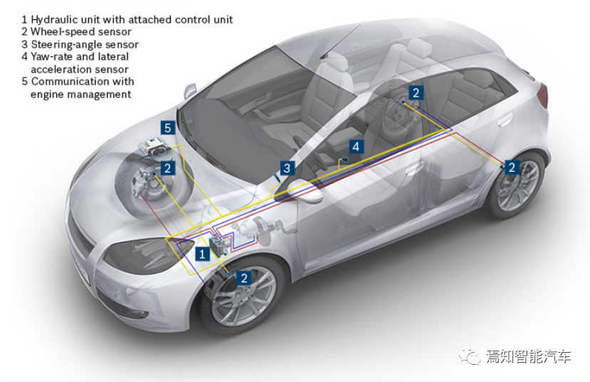
Key Components of VDC Control System
① Hydraulic Control Unit
② Wheel Speed Sensor
③ Steering Wheel Angle Sensor
④ Inertial Sensor (Yaw Rate, Longitudinal Acceleration, Lateral Acceleration)
⑤ Drive Force Control Unit (through CAN interaction)
Among them, the wheel speed sensor calculates the speed information of the four wheels in real time through filtering and counting technology. The steering wheel angle sensor monitors the steering wheel angle in real time. The inertial sensor monitors the dynamic behavior of the vehicle in the horizontal axis and the vertical axis in real time. These pieces of information, which characterize the vehicle’s state, are input to the ECU, which decides on the wheel cylinder hydraulic pressure and the driving force of the engine or motor through the VDC core algorithm. This achieves real-time adjustment of vehicle attitude and ensures that the vehicle always exhibits good stability and controllability.
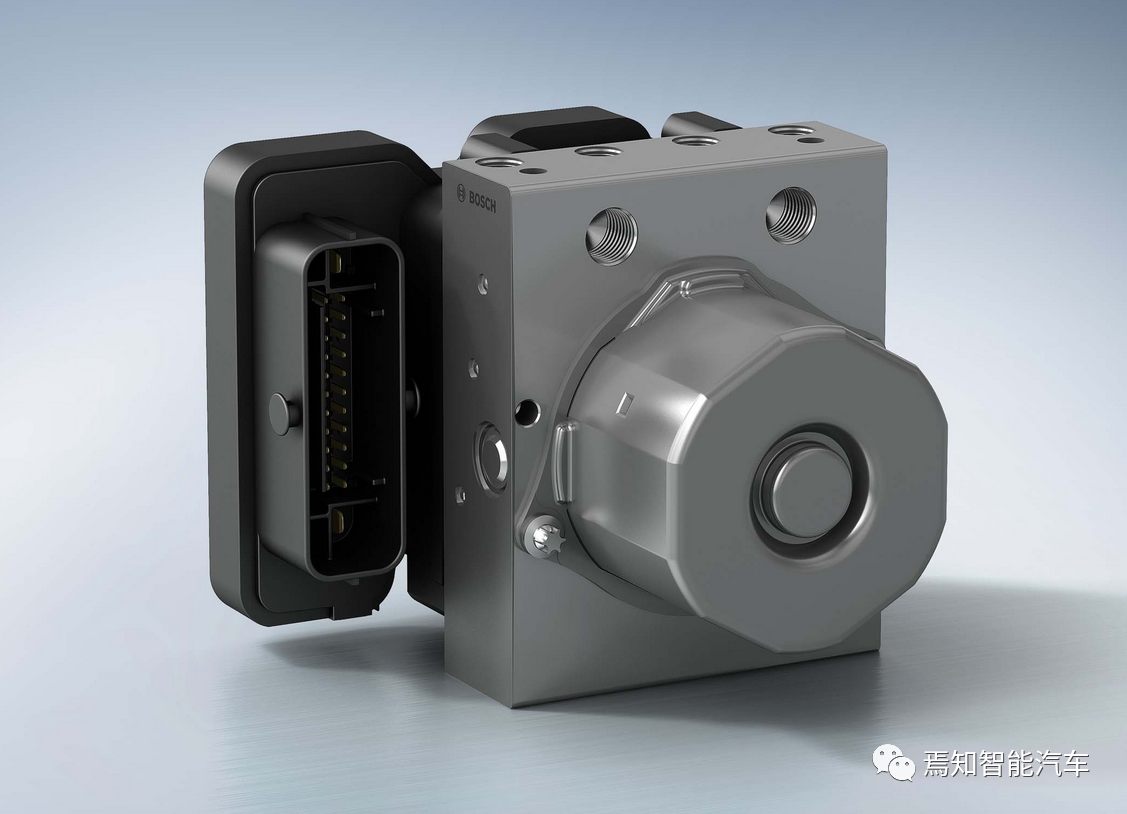
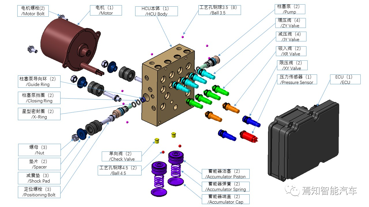
The following figure shows the design of the hydraulic system (HU: Hydraulic Unit) that supports VDC function. The HU has 12 high-speed switching valves, including 2 suction valves and 2 pressure limiting valves, which isolate the brake pipelines from each other during the VDC process; and 4 pressure increasing valves and 4 pressure reducing valves, which achieve single-wheel pressure regulation through valve opening and closing combinations. In addition, there is a pressure sensor at the front end of the suction valve. VDC determines whether the car is braking forcefully, lightly, or actively through the pressure sensor.
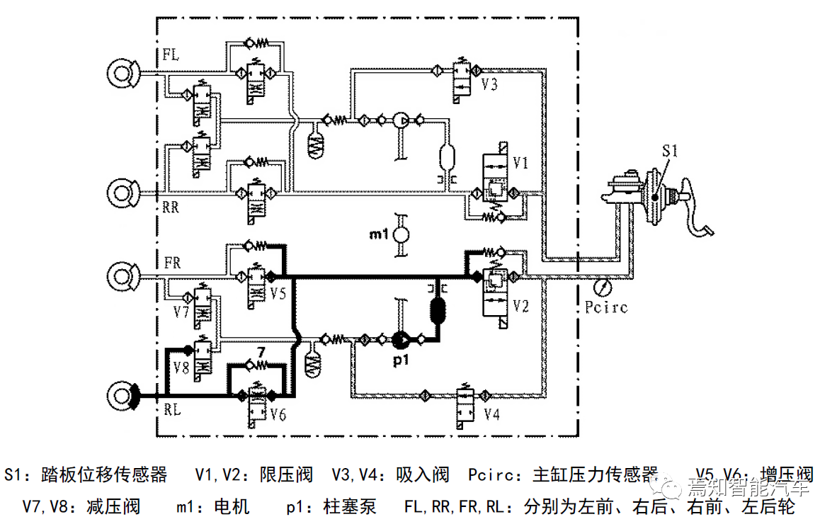 When VDC is active, active boosting is required. Take the example of RL single-wheel boosting for the left rear wheel: Motor m1 drives plunger pump p1, V2, V3, and V4 are powered on, separating the FL and RR brake circuits. Brake fluid is pressurized by plunger pump p1 through suction valve V4, and after boosting by RL boosting valve V6, it enters the RL wheel cylinder to achieve active boosting. To relieve the pressure, suction valve V4 is turned off while pressure-limiting valve V2 is opened. Therefore, during VDC operation, plunger pump P1 acts as a booster pump. In addition, pressure-limiting valves V1 and V2 can protect the HCU circuit during active boosting. When the pressure exceeds a certain limit, the pressure-limiting valve opens to maintain the internal pressure of the HCU from rising further.
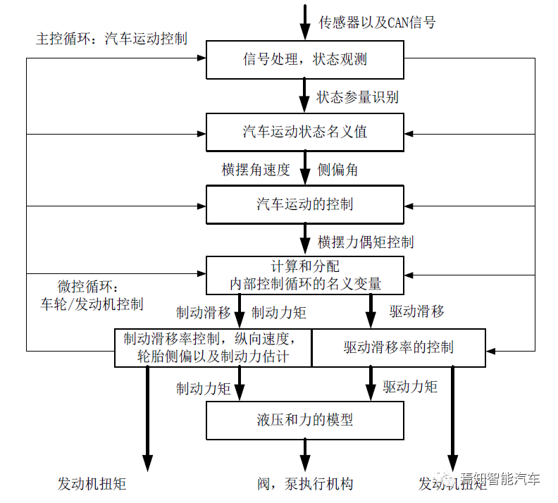
The functional architecture of VDC is shown in the figure below. The implementation of VDC technology mainly includes the controller, control algorithms, executive mechanisms, and system matching calibration, among which the control algorithm is the core of VDC technology. The implementation of control algorithms needs to solve three problems: identifying the driver’s driving intent, observing the vehicle’s dynamic state, and controlling methods for different dynamic states.
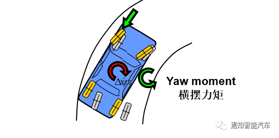
When there is insufficient steering, the lateral angular velocity is too small, causing the front axle of the vehicle to slide towards the outside of the bend. At this time, VDC applies braking force to the inner side of the bend to generate a reverse lateral angular velocity, thereby stabilizing the vehicle in the expected lane.
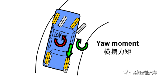
When there is excessive steering, the lateral angular velocity is too large, causing the rear axle of the vehicle to slide towards the outside of the bend and causing oversteer. At this time, VDC applies braking force to the outer side of the bend to generate a reverse lateral angular velocity, thereby stabilizing the vehicle in the expected lane.
Conclusion## English Markdown Text
Since 1 November 2011, all new cars sold in the European Union must be equipped with vehicle stability control system (ESC) due to the mandatory requirement by the EU in 2009. Therefore, ESC has become standard equipment for new cars in Europe. Although there is no mandatory requirement of ESC for China’s automobile industry, almost all vehicles sold for more than 100,000 RMB are now equipped with ESC as it plays an irreplaceable role in ensuring driving safety, which makes it widely recognized and applied in the market. From this perspective, it is not an exaggeration to say that the ESP product integrated with the VDC function is a revolutionary product.
This article is a translation by ChatGPT of a Chinese report from 42HOW. If you have any questions about it, please email bd@42how.com.
