Module Design Details
Arrangement of Cells in Modules
In the design of this large module, there are 77 cells in parallel and 22 cells in series, for a total of 1584 cells in each module. The cells are arranged in a positive/negative alternation to achieve electrical connection between cells. The connections of the positive and negative terminals of the cells in the module are illustrated below.
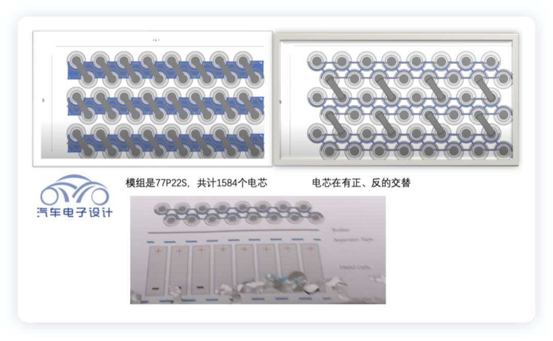
This diagram, together with the following one showing the welding points of the cells, may help to better understand the arrangement. Engineers who are currently working on cylindrical cells have told me that the process of designing modules with cylindrical cells is actually more challenging than that of prismatic cells or pouch cells from the perspective of manufacturing process and technology.
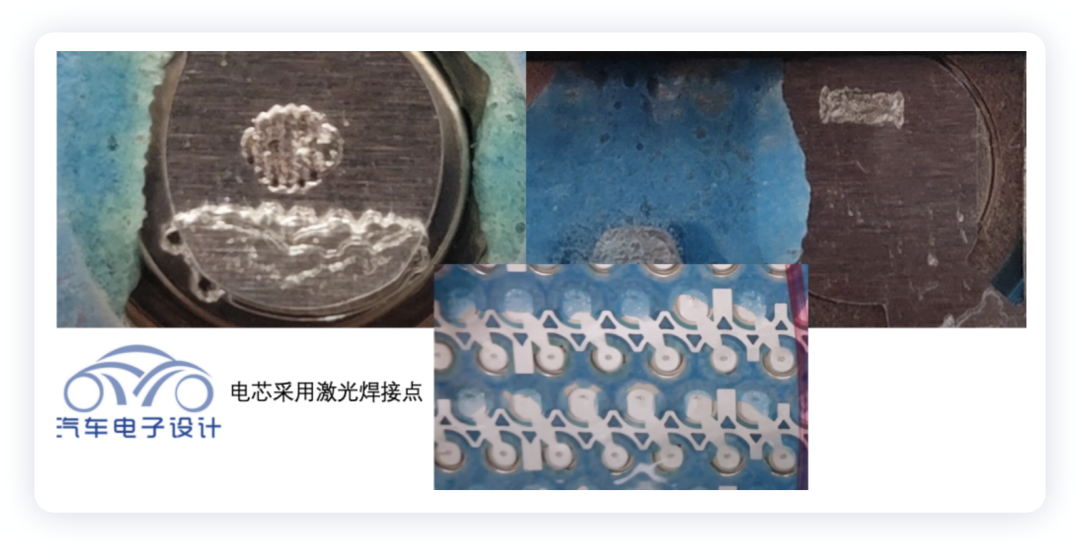
Details of Module Design
Arrangement of Cells in the Module
The battery pack of the Model S Plaid uses a very compact module design, which includes a new water-cooling system. The bi-directional U-shaped water pipes divide the water channel of the cooling system into two parts, allowing for the inflow and outflow of the cooling water in the upper and lower parts of the module.
Electrical Connections between the Modules
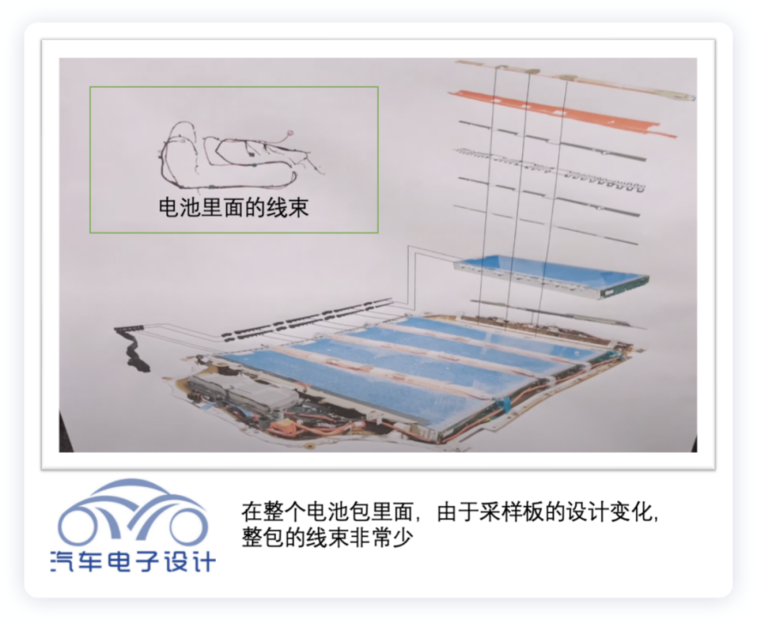
In terms of the electrical connections between the modules, there is a trend toward integration with structural design. As the sampling board circuit board plays a role in the connections, the wiring in the module was further reduced. The design of the connection between the sampling board and the Busbar is also worthy of our close attention.
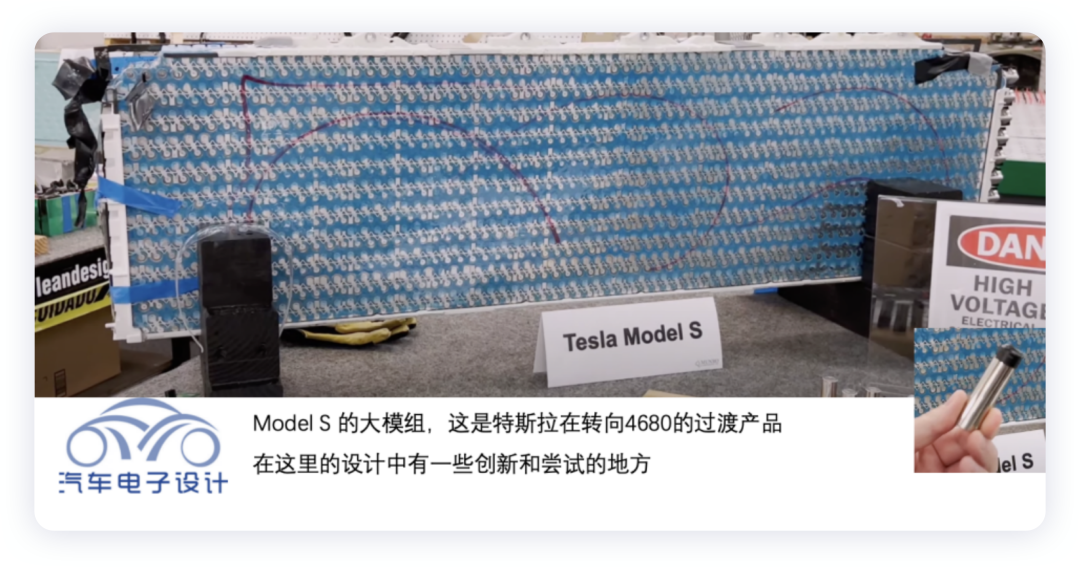
The photo below shows a close-up of the Model S Plaid module. As Tesla engineers transition to the 4680 cell format, they have made many attempts in the design of modules.
 ### Water Cooling Design of Model S Plaid
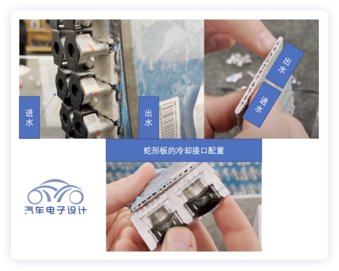
Due to the use of the Kirin battery, the design of the water cooling plate has attracted high attention. As shown in the figure below, we can clearly see the design of the flow path and interface of the serpentine water pipe at the end face of the Model S Plaid. From the cross-section, we can see that there are 13 channels in the liquid cooling pipe, 6 of which are used for inlet and 6 for outlet. The direction of the water flow for the module can be controlled by the joints of the liquid cooling pipe below, while the layout of the water cooling pipe can be completely arranged on one side.
On one end of the module is the water cooling solution, and on the other end is the wiring harness connection for the sampling board.
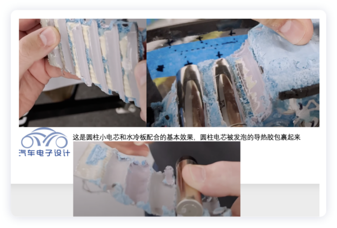
Inside the module, the battery cells are structurally connected to the liquid cooling pipe through foamed thermal adhesive. The height of the cooling pipe of the S Plaid covers the cylindrical surfaces of the 18650 battery cells. According to Chiba’s calculation, the aim of this design is to maximize the cooling surface area. The blue foaming thermal adhesive used for encapsulation has a high fixation effect. Even Mr. Monro could hardly peel it off directly by hand, which is caused by the changed bonding effect of the adhesive.
Design of Electrical Connection for Modules
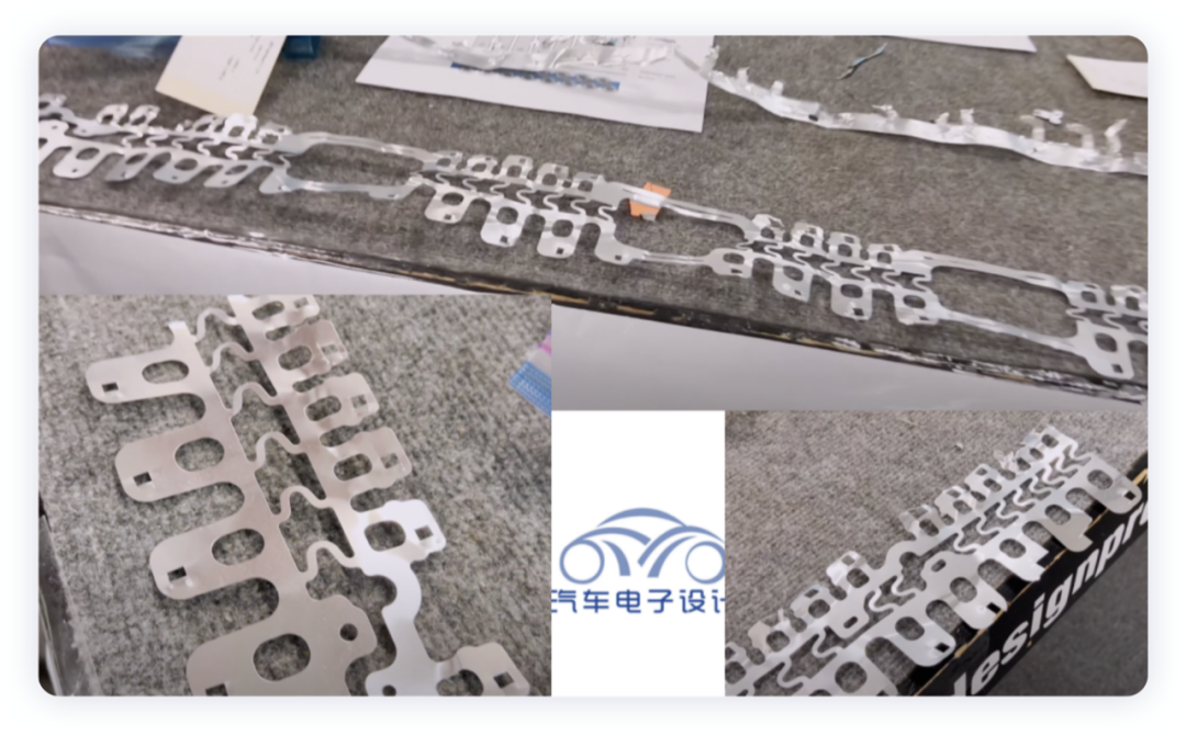
In the five large modules, multiple fixing structures are arranged on both sides of each module when horizontally placed, and they are fixed with bolts on the horizontal beams inside the lower box. The module-to-module busbar connection is achieved by welding, and the adjacent two modules are connected by the common bus, which goes through the central arched channel (over 700A) for high current in the modules. Therefore, Tesla chooses to have a certain conductor overflow design between the modules, which is actually related to its use of a single Pyrofuse for precise control. If the Pyrofuse fails, this weak point design with hard metal connection can achieve the same level of fuse.
There are four weak points inside the connection of the five modules, and one of them can always be fused completely.
BMS Sampling Board
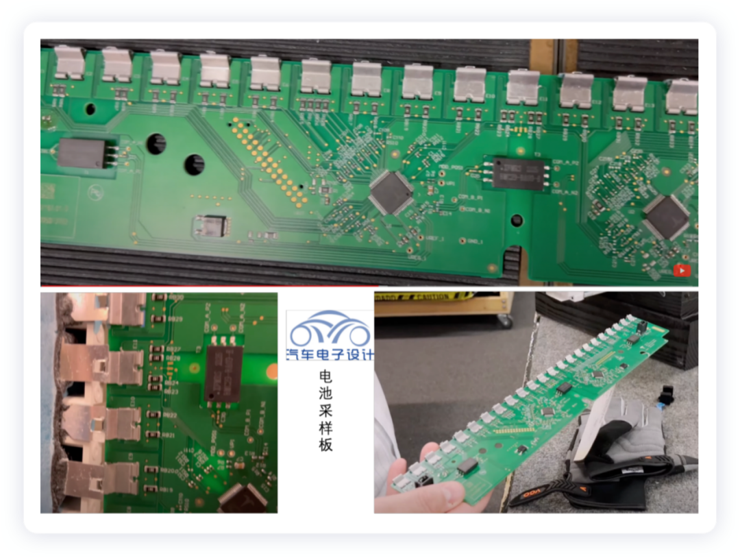
First of all, let’s take a look at the design concept. Currently, the sampling board has become a design similar to the end plate, as shown in the figure below. By directly connecting the busbar to the single end, the FPC is eliminated, which means that the connection process of the busbar and the combination with the sampling point are considered together, and there is no need for a dedicated sampling wire to pass through the module.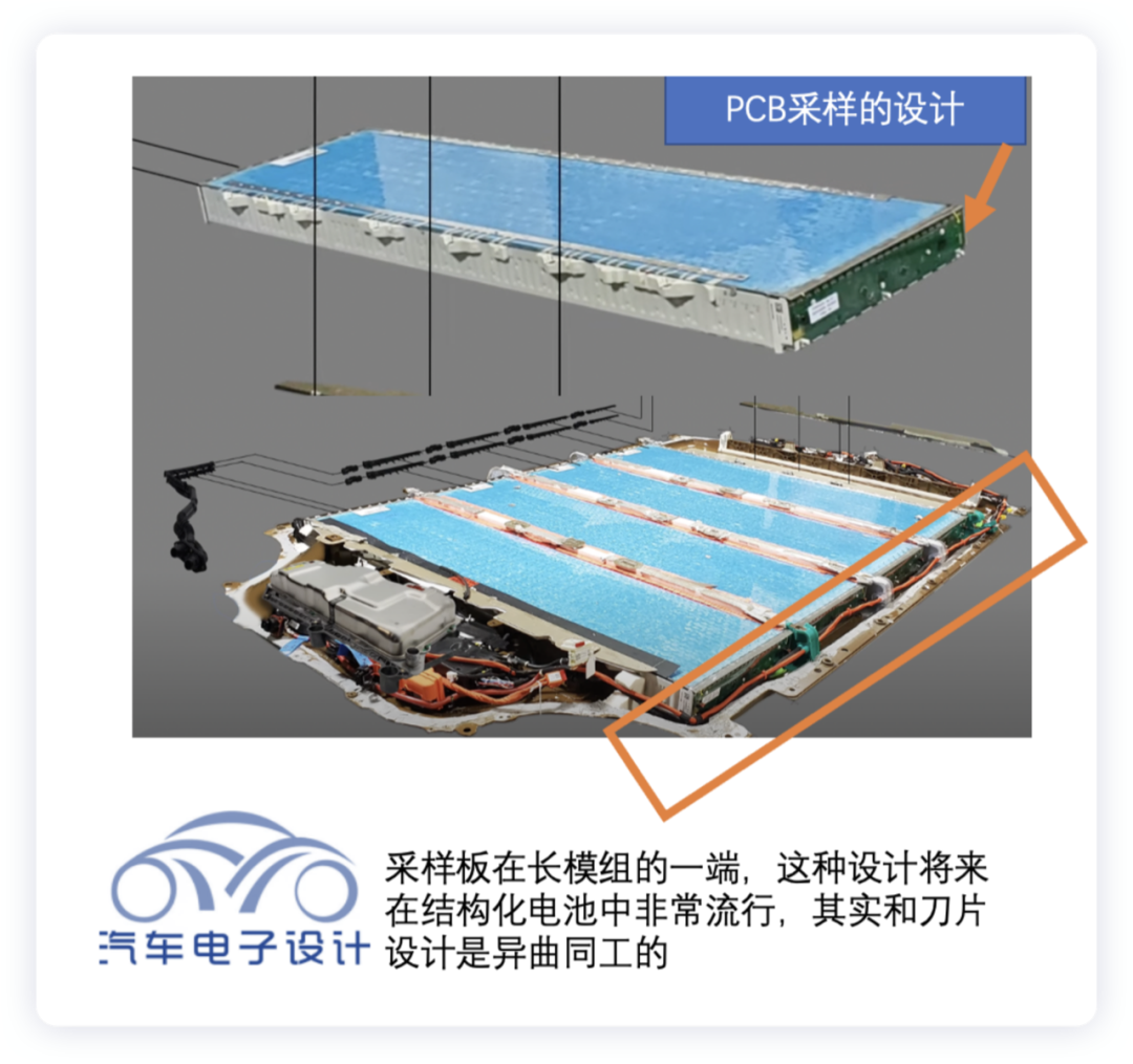
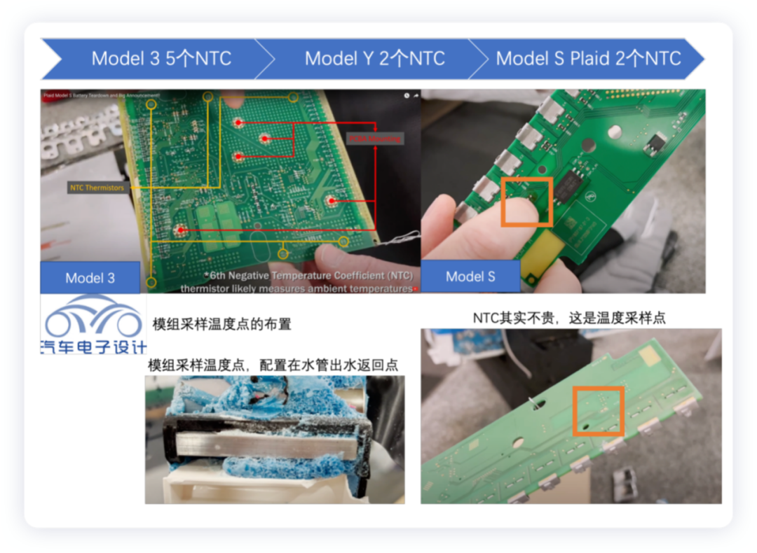
The temperature sampling of the module is achieved by directly integrating NTC on the circuit board, with the quantity decreased from five to two, making contact with the bottom of the liquid cooling tube through metal points. With such a long module, only two NTCs are used, distributed at both ends of the sampling board, simplifying the process and reducing the space and sampling line circuits needed for embedding NTC directly into the module.
I have been observing Tesla’s designs, and it turns out that many basic components are continually optimized in quantity, making it difficult to assess the prospects of secondary companies using the value of battery packs. This is because the VAVE of engineering design is continually reducing costs, not to mention the direct supplier price competition.
The battery sampling board is now designed more simply, using a single-sided board.
In summary: when the 4680 structured version of Model Y is released, we can carefully discuss the details of the design. With the help of friends, I am working hard to produce a video every week to explain these designs in a way that is easy to understand.
This article is a translation by ChatGPT of a Chinese report from 42HOW. If you have any questions about it, please email bd@42how.com.