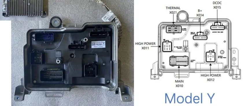
Evolution of Vehicle Wiring Harnesses and Value Changes
Author: Zhu Yulong
When discussing the electronic and electrical architecture, I find it interesting to think about how the number of cables and electrical connections outside the EE components in the entire wiring harness will change during the iteration of the domain control system and the wire harness design process in the popularization of the next generation of smart cars.
Following this train of thought, I looked at Tesla’s Part List and Wiring Diagram to explore the evolution of the entire vehicle wiring harness assembly and the change in its value:
- I mainly focused on the self-made domain controller, self-made core controller, and power assembly domain controller (2+4+4=10), counting the MCUs and low-voltage connectors used.
- Then I counted the connectors and ECUs used by external controllers – this part is similar to other car companies, and currently there are 7-8.
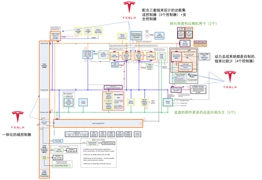
- The entire 12V cable mainly includes:
12V battery wiring harness, instrument panel and console wiring harness, door and trunk wiring harness, front bumper and front-end wiring harness, top cover wiring harness, main front and body wiring harness, rear bumper and subframe wiring harness, seatbelts and windshield wiring harness, and a list of coaxial and special cables in Model 3.
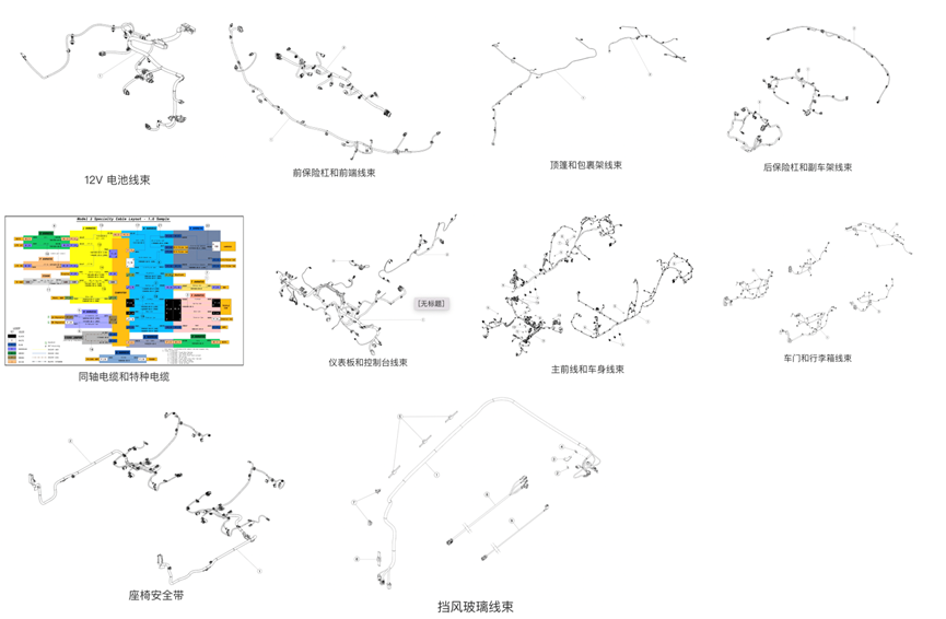
Tesla’s Domain Controllers
Tesla’s design is developed with the main control domain controller (infotainment and Autopilot) and the distribution and left-right body controllers.
- Central Computing Module
Mainly includes: infotainment system, advanced driver assistance system and overall vehicle gateway communication system; the gateway is divided into Private CAN, Vehicle CAN, Chassis CAN three CANs (backbone network).
- Private CAN
Customized, connected to six core self-made controllers (infotainment/Autopilot, electric drive module, VCR controller, left-right body controller) and several core external components, such as the steering assist and brake (I-booster+ESP) and airbag controllers for the chassis. These are Tesla’s core systems, carrying information exchange of functional modules involving vehicle safety, basic driving, and chassis control.
-
Vehicle CANLink homemade components (three major body controllers), high-voltage management module, VSC (Security Controller), and external component electric compressor and steering information to achieve traditional body domain functions (load control, air conditioning, owner access), and high-voltage management.
-
Chassis CAN
The most traditional, connecting tire pressure, braking, steering, airbags, etc. Tesla should consider safety in this aspect.
Of course, these are the main communication connections, distributed on the communication interface of this controller – my understanding is that Tesla has gradually compressed the unnecessary external supplier ECU, in fact, we can no longer see pure ECU, they are all electromechanical integration or electric control units with safety functions.
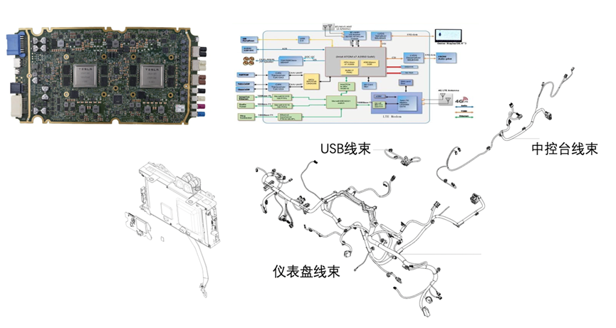
The following Figure 4 is more meaningful, because this controller mainly needs to connect with external video sensor interfaces and other relatively high-speed interfaces. As this aspect is developing rapidly, with the increase of screen interfaces, cameras, and lidars, the key increase is in this part.
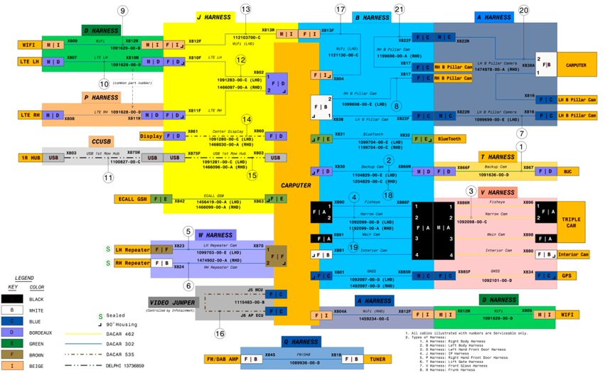
Tesla’s three main controllers
This part of the content is relatively large, I will start with an introduction today and expand on the interface and chip of each component tomorrow. Let’s take a look again, the three integrated controllers actually integrate many functions, which have been explained before.
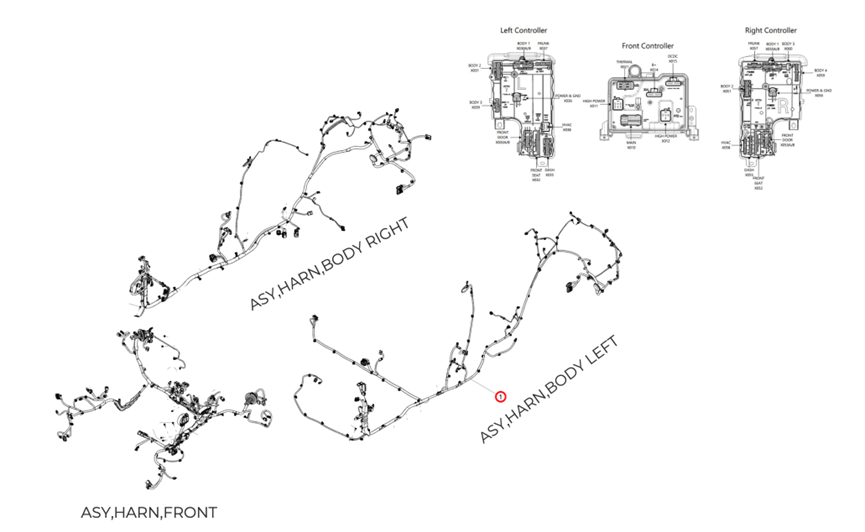
- Front body module
Responsible for 12V battery, power distribution, and thermal management functions, like the harness below, it is located in the front of the vehicle and includes windshield wipers, front trunk, external lights, and air conditioning. We will organize the harness connection and functional diagram of this part tomorrow, and iterate to Gen3.
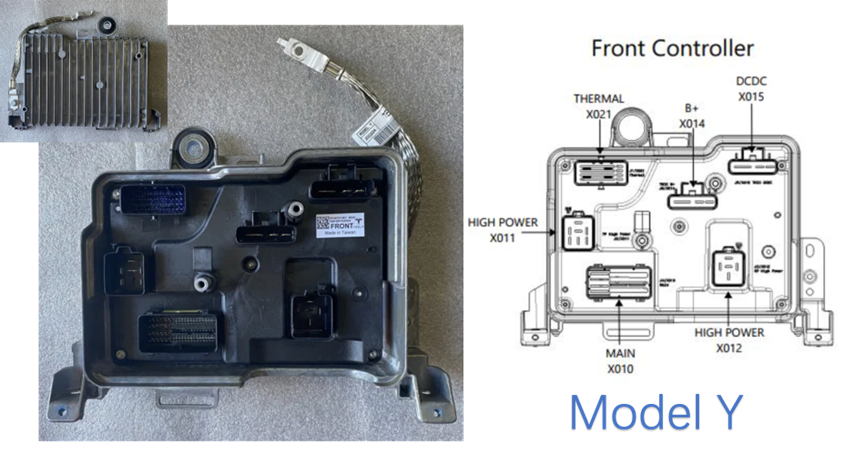
- Left body control module
Focus on the traditional body domain functions such as lights and access. The air conditioning system includes the blower motor drive distribution. My understanding is that it achieves near configuration control based on load location. This controller is iterated to Gen3.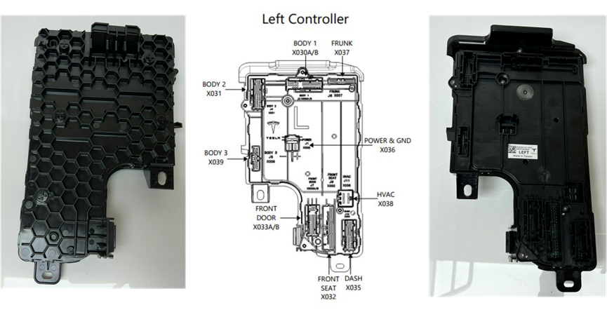
- Right Body Control Module
Responsible for functions such as air conditioning, power windows, interior and exterior lighting, parking, and parking assist signal acquisition. It also includes some of the air conditioning system’s sensor signal acquisition, load driving, as well as some high-level brake light, position light, and left and right reversing light driving, iterated to Gen3.

Summary: I have been thinking recently that as Tesla iterates over several generations in chip, functional design, software, and production, we really need to consider where the destructiveness of traditional automotive electronics lies. Connecting all the information to see what the car companies are doing, how Tier 1 companies are cooperating with such car companies, and what core opportunities are emerging.
This article is a translation by ChatGPT of a Chinese report from 42HOW. If you have any questions about it, please email bd@42how.com.
