Author: Zhu Yulong
Following the previous article “Mercedes-Benz NTG7 Cockpit and HERMES3 Vehicle System“, Mercedes-Benz’s T-box HERMES 3 is now in the final stage of wireless certification. Currently, most of the available information online mainly focuses on the different versions of HERMES2. In this article, I would like to discuss whether there is independent value for T-box in the course of its development, apart from the added V2X connection feature (which will be discussed separately in the second part).
HERMES is an acronym for Hardware for Enhanced Remote, Mobility, and Emergency Service. It has been designed since the first generation, including GSM, UMTS, LTE, USB, Bluetooth, and Wireless LAN.

Mercedes-Benz’s HERMES 2
The currently available information mainly includes the overall system diagram and T-box diagram:
-
HUH: Head Unit High (the main component of the infotainment system)
-
OHCM: The panel includes B/E/I call buttons (used to trigger calls) and corresponding LEDs (used for call indication)
-
CPC/OBC/HVAC: The components of the vehicle air conditioning system
-
DBE: Panel input for phone numbers
-
EIS: Ignition status signal
-
IC: Liquid crystal instrument cluster
-
MFL: Control element integrated in the steering wheel
-
ORC: Safety airbag signal
-
ESP: Wheel speed signal
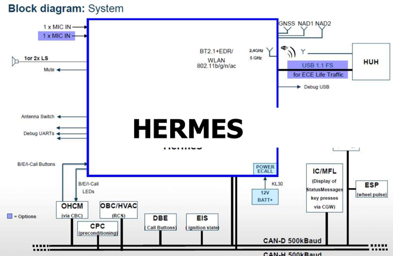
For the cockpit, the main transmission of the overall vehicle network is through the 500k CAN bus, with one wireless WIFI connection and one USB 1.5 connection.
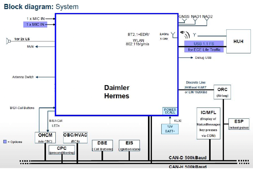
 We compared the system design of Mercedes-Benz from 1.5 system iteration to 2.0, and it was completely consistent in terms of interface, which is the traditional approach for maintaining backward compatibility. The main functions include providing network access for different remote information processing services, and providing E-Call, R-Call, and I-Call services.
Inside this T-box, it mainly includes the NAD module, Huawei module (Networ Access Device Module), SOC Hisilicon Hi6932 (BB), Hi6559 (PMU), Hi6362 (RFIC), NAND FLASH 512MB, and RAM 256MB, which runs Linux and is mainly aimed at the connection antennas of two NAD channels, GNSS functionality, Bluetooth, and wireless connectivity.
The control’s CoPilot is a core MCU SH726A @ 216MHz SPI Flash 2MB, RAM 1.25MB, which can complete two high-speed CAN bus connections and LIN connections for Airbag, and handle button and power diagnostics from a diagram perspective.
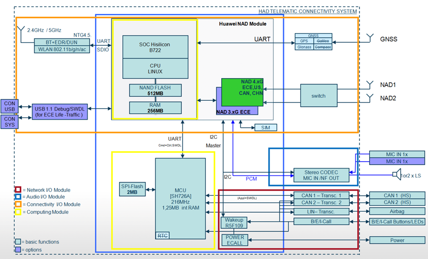
The MCU itself doesn’t have much work, mainly serial communication with NAD, and some simple peripherals and communication.
Note: The MCU in the ECU of traditional cars seems to be like this, and it doesn’t do too much work.
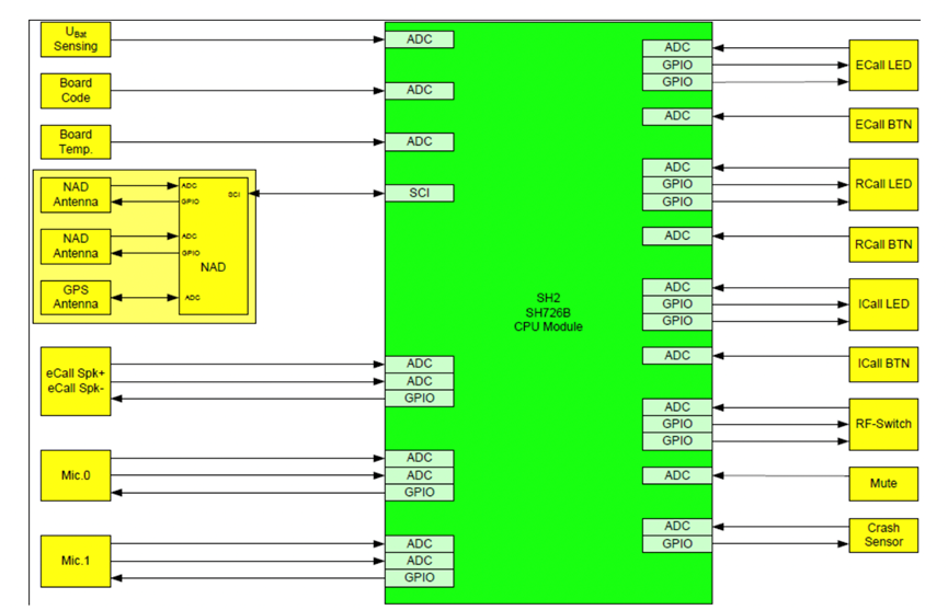
HERMES didn’t provide an overall diagram, it should be consistent judging from the structure.

Due to the requirement of functional safety for speech integrity, the path of speech is shown here.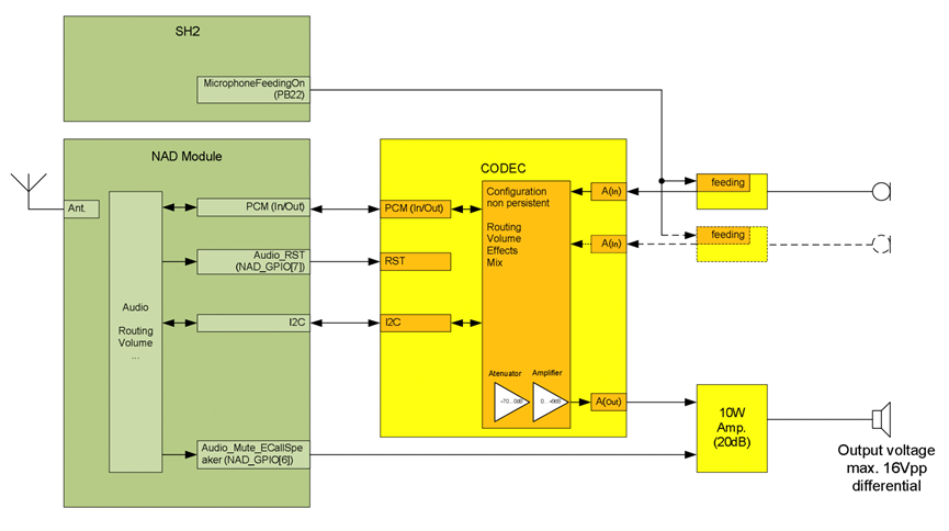
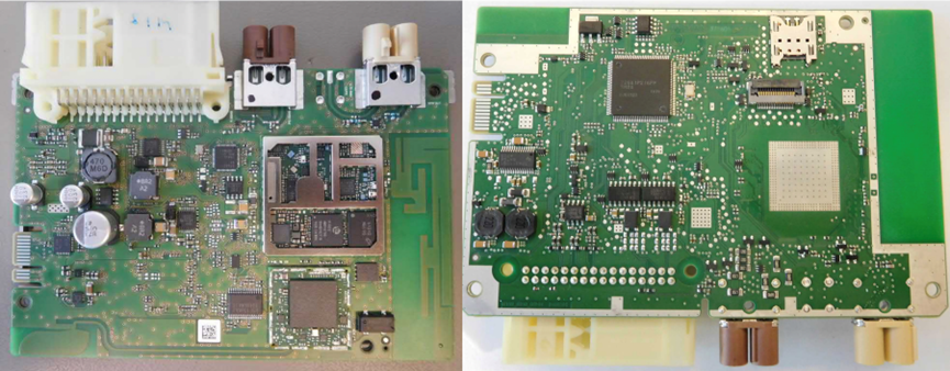
Figure 9 shows the exploded view of both sides of the T-box mentioned earlier: Huawei’s NAD module, which contains multiple chips.
Should T-Box exist independently?
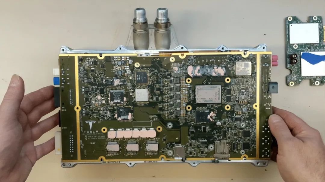
From a distributed to a centralized approach, it is entirely possible to create a single board similar to Tesla’s, which includes the above-mentioned NAD modules, wireless Bluetooth modules, etc. This board, when combined with the main control board, can be designed as a layered sub-board and main-board model, while still including the Co-pilot MCU in the cockpit main board, thereby realizing CAN communication in HERMES, various connections, and even the direct inclusion of Gateway within the board. In general, things can be greatly simplified.
My personal opinion: With the advent of centralized domain control, connecting units like T-boxes will undoubtedly become obsolete unless for the sake of EMC complexity.
-
NAD network access and wireless connection modules are integrated into a replaceable board.
-
The software layer is centralized in the domain-controlled SOC, while the emergency function is retained in the MCU.
Considering the reliability from an electrical and structural perspective, there will likely be many host designs in the future, similar to industrial considerations. How to design these boards in a serial structure, achieve plug-and-play maintenance and assembly, and balance the total cost is important.
In summary, I believe that many wire harness connections are artifacts of the distributed era. By integrating these core functions and redefining system functions, numerous MCUs can be merged into similar items, which in themselves do not require complex processes, simplifying related low-voltage connectors and low-voltage wire harnesses.
This article is a translation by ChatGPT of a Chinese report from 42HOW. If you have any questions about it, please email bd@42how.com.
