Author: 一片緑葉
Many people have misunderstandings about NIO, thinking that NIO’s charging technology is not good enough that’s why it is focusing on developing battery swapping stations instead of charging stations.
NIO firmly believes in “rechargeable, replaceable, and upgradable”. Therefore, while NIO rapidly expands its battery swapping station network, it has not neglected the development of charging stations. The construction speed is at the same level as Tesla and XPeng.
The following picture shows the types of charging stations that NIO currently has, including 7kW home charging stations, 20kW small DC fast charging stations, and supercharging stations. In addition, NIO has also introduced 7kW and 11kW DC home charging stations.
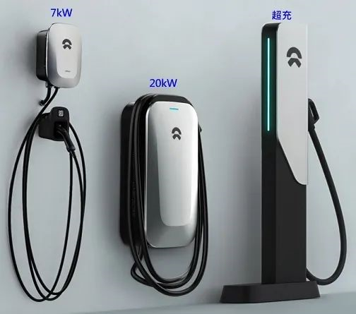
The 7kW home charging station is called an “AC charging station” because it uses AC power as input power, and it relies on the On-Board Charger (OBC) to convert the AC power to DC to charge the vehicle. As for the commonly heard fast charging and supercharging, they are all DC charging stations.

Whether it is an AC or DC charging station, the principle of AC-DC conversion is the same. Therefore, “we can establish the concept of charging technology by starting from the circuit topology of the On-Board Charger (OBC)”.
Introduction to Charging Technology
PFC Power Factor Correction
PFC is a circuit that improves the “power factor”.
To talk about power factor, we must first understand the concept of AC power:
- Real power (measured in watts), represented as P;
- Reactive power (measured in VAR), represented as Q;
- Apparent power (measured in VA), represented as S.
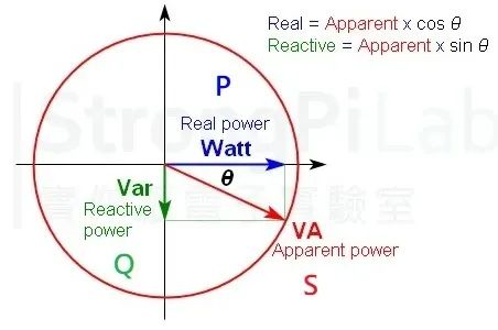
For a sine wave, P, Q, and S can be represented by phasors. θ is the phase angle between current and voltage, and the power factor equals cosθ.
P/S = cosθ
Because it is cosine θ, the power factor is a numerical value between 1 and -1. By adjusting the input current waveform of AC power, reducing the phase difference between voltage and current, suppressing harmonic currents, the power factor can be close to 1.
 Simply speaking, the function of PFC is to achieve stable output voltage regulation without being affected by input voltage fluctuations, and active PFC has low DC voltage ripple, which does not require large filter capacitors. In addition, it suppresses high-order harmonics, which can cause heating and energy waste in the power system and even lead to burnout.
LLC is a series-parallel resonant circuit with resonant inductance Lr, excitation inductance Lm and resonant capacitor Cr, hence the name LLC. Resonance refers to “resonance”. Resonant circuits utilize inductance (L) and capacitance (C) to achieve circuit resonance, and the impedance of AC circuits is not constant but varies with frequency.
The impedance (Electrical impedance) is a measure of the resistance of the circuit to the current (symbol Z). In AC circuits, it is divided into real part and imaginary part, where the real part is resistance and the imaginary part is reactance (the active power is the real part, and the reactive power is the imaginary part in the figure above). Reactance is further divided into capacitive reactance generated by capacitors and inductive reactance generated by inductors, and both change with the frequency of the circuit’s current (while resistance does not).
Capacitive reactance = 1/2πfC, which increases at low frequencies and decreases at high frequencies. The direct current frequency is 0 and the capacitive reactance is infinite, so that capacitors are used to pass through alternating current and block direct current.
The voltage across a capacitor cannot change suddenly.
Inductive reactance = 2πfL, which is opposite to capacitive reactance. It decreases at low frequencies and increases at high frequencies. The direct current frequency is 0 and the inductive reactance is 0, so that inductors are used to pass direct current and block alternating current.
The current through an inductor cannot change suddenly.
When capacitive reactance equals inductive reactance, the reactive power is 0 and only active power needs to be considered. By controlling switch frequency (adjusting frequency), the DC is adjusted to the target waveform to achieve constant voltage regulation, using the characteristics of capacitance and inductance.
This is a DC characteristic curve drawn by FHA for designing an LLC circuit.
ZVS (zero voltage switching), the voltage across the power electronic component is 0 when switching.
ZCS (zero current switching), the current through the power electronic component is 0 when switching.
Divided by the resonance point Fs = Fr.
- When capacitive reactance > inductive reactance on the left side, the resonant tank becomes the capacitive area, which requires ZCS, and the voltage lags behind the current, suitable for IGBT.
- When inductive reactance > capacitive reactance on the right side, the resonant tank becomes the inductive area, which requires ZVS, and the current lags behind the voltage, suitable for MOSFET.As the turn-on loss of MOSFET is larger than turn-off loss (about 60%), ZVS (zero-voltage-switching) is chosen. And in the ZVS region, the condition of ZCS (zero-current-switching) for the output rectifier diode in zone 2 eliminates the problem of reverse recovery and achieves the highest efficiency.
Finally, DC is output to the battery pack through synchronous rectification.
Wireless Charging

There are mainly four types of wireless charging: electromagnetic induction, magnetic resonance (also known as magnetic-coupled resonance), electric field coupling, and radio wave.
Electromagnetic induction is the most common wireless charging method in daily life, but it is not suitable for electric vehicles because the transmission distance is too short (up to a few centimeters).
Electric field coupling has fewer restrictions on the shape and material of electrodes, and electrodes can be thin, with less heat generated and more freedom in position than electromagnetic induction. However, like electromagnetic induction, its drawback is that the distance is too short.
Wireless radio wave has the farthest distance, but the conversion efficiency is too low. Only magnetic resonance meets the wireless charging standard of electric vehicles in terms of distance, power, and conversion efficiency.
Since it is a magnetic resonance, a resonant circuit is naturally used. Different from the LLC used in charging piles, there are several choices of resonant circuits for wireless charging:
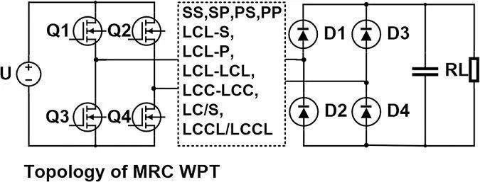
Q1 to Q4 are four primary (transmitting side) MOSFETs, and D1 to D4 are secondary (receiving side) rectifier diodes. Similar to the charging principle of charging piles, it becomes wireless and the choice of resonant circuit is different.
1. Types of Resonant Circuits
S-series circuit, in which the capacitor and inductor are connected in series, is connected directly to the voltage source inverter for the primary side. It has low input impedance and low losses and is easy to achieve voltage feedback regulation.
For the secondary side, it has similar characteristics to a constant voltage source (output voltage is stable).
P-parallel circuit, in which the capacitor and inductor are connected in parallel, requires power supply from a current source for the primary side, is easily disturbed, and has fewer practical applications.
For the secondary side, it has similar characteristics to a constant current source (output current is stable). Therefore, SS is a series circuit on both sides, PP is a parallel circuit on both sides, SP is series on the primary side and parallel on the secondary side, and PS is parallel on the primary side and series on the secondary side.
LCL can provide a constant current source, has a high power factor and harmonic filtering capability under light loads. Other types are extensions based on the topologies of the above three circuits, optimized for stability, input impedance, and system transmission.
Taking NIO’s wireless charging patent layout as an example, NIO has had a layout in wireless charging for electric vehicles early on and has optimized the circuit topology for the DDQ coil. The performance of the coil coupling structure is an important factor affecting the transmission of electric energy in magnetic resonance wireless charging.The design focus is on how to improve the coupling coefficient, the actual mutual inductance between two inductors is between -1 and 1, which also indicates the ratio of actual to maximum mutual inductance.
2. Inductor Coupling Structures

There are three basic types: toroidal coils, 8-shaped coils (DD), and helical coils:
- Toroidal coils have the advantages of easy winding, low core and copper losses, but their coupling is poor.
- DD coils are similar to toroidal coils, consisting of two toroidal coils connected in reverse to produce opposite magnetic fields. The coupling coefficient and loss are between those of toroidal and helical coils.
- Helical coils are typical copper-clad iron structures with concentrated magnetic lines and high coupling coefficients, but high core and copper losses.
Like wireless charging for smartphones, the coupling coefficient is strongly influenced by the distance and displacement between two coils, as shown in the following figure:
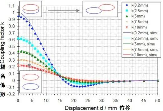
This is the test result of two 30 cm (circular) toroidal coils. The coupling coefficient changes when the coils are aligned axially and translated.
A negative coupling coefficient indicates that the magnetic flux directions of the two coils are opposite.
3. NIO’s Wireless Technology Solution
In practical applications, it is difficult to park manually and align the coils perfectly, which may not ensure sufficient transmission power. Increasing the size of the coils will increase the cost and weight.
DDQ is a form of coils designed to solve the problem of positional offset, which causes a decrease in transmission power and efficiency. After offset, the induction voltage of the DD coil decreases while that of the Q coil increases, and the two coils are superimposed to output, which can minimize the decrease in power.
DDQ coils look like this:
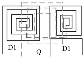
DDQ coils are based on DD coils, with an additional orthogonal coil Q that generates a magnetic field that does not affect the DD coil. The two coils output separately, and the output voltage is parallelized through two rectifier bridges.
However, a new problem arises. Because the DD coil and Q coil receive different magnetic flux, it is easy to cause uneven output current or even no output, which can reduce efficiency and affect EMI properties. Conventional rectification circuits cannot solve the problem of uneven output current.
CN108400625A is a circuit topology solution to this problem.
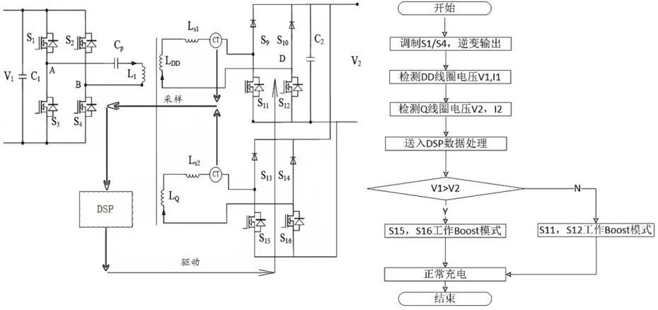 Although NIO has already set out a wireless charging plan early on, future vehicle models have removed the On-Board Charger (OBC), which may have already rendered NIO obsolete for wireless charging that requires the installation of receiving coils on the bottom of the vehicle.
IV. Other automakers’ wireless technology solutions
SAIC IM
As mentioned earlier, it is difficult to accurately match the positioning manually; thus, some automakers particularly emphasize the function of automatic parking.
IM L7 claims that its IM AD system can achieve memorized parking and valet services. By using vehicle surround-view cameras and extracting special micro-points through VSLAM (Visual SLAM), combined with the vehicle’s IMU (Inertia Measurement Unit) for self-positioning, it can also make path planning and movement control based on the parking lot or parking space maps.
Finally, precise parking is achieved through data fusion from multiple sensors, but there is a danger of the electromagnetic field heating up metal or biological objects when there is a gap between the transmitting and receiving coils during wireless charging, which is very unsafe.
Therefore, Foreign Object Detection (FOD) and Living Object Detection (LOD) are important safety features of the wireless charging device. However, IM’s promotion or patents do not mention any relevant inspections.
On the other hand, General Motors’ Wuling has registered related patents and can use the vehicle controller to clear them.
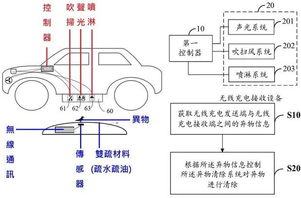
A dual hydrophobic and oleophobic material, such as fluoroacid polymer or organosilicon polymer, should be applied to the top surface of the transmitting side to make it smooth and less adhesive to form an easy-to-clean surface. When sand or water droplets or oil stains fall on the top surface, they will slide off automatically.
Sensors should be installed on the transmission side to monitor the wireless charging station, and the foreign object messages should be transmitted to the vehicle controller through wireless communication.
The main judging criteria here are “weight or image recognition” (based on what kind of sensors are used in the implemented wireless charging station). Finally, depending on the type of foreign object, it is decided to take what kind of manual cleaning method.
If blowing, sound and light, and spraying are all unable to clear the foreign object, the vehicle owner should be notified to remove it manually.
It remains unclear how much of Wuling’s technology IM will use, but hopefully, more is better, as safety is of utmost importance.
Momentum Dynamics
Since there are companies that focus on precision positioning for wireless charging for electric vehicles, there are also companies that focus on large coil sizes.
Momentum Dynamics is one of them.
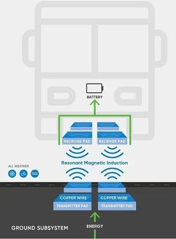
Although there are only four small squares on the receiver side in the illustration, in reality, each block is more than 70 cm long and wide, with a power of 50 kW. The total of the four blocks is 200 kW.“`markdown

According to Momentum Dynamics, the charging efficiency is between 92-94% when the best distance is about 7 inches (17.78 cm) between the sending and receiving sides, which is close to the efficiency of ordinary DC charging piles.
For the scenario of bus usage, the advantage of wireless charging is that it is easy to operate, saves time for manually plugging and unplugging charging piles, and utilizes fragmented waiting time to avoid wasting time on extra charging, which can keep buses in service all day and improve bus utilization.
Moreover, buses have fixed routes and stops, so it is suitable to install fixed wireless charging sending sides and related charging cabinets.
Compared to trams, it does not require the laying of cables on the road surface, but only needs sufficient local capacitance and site allowance to be installed.
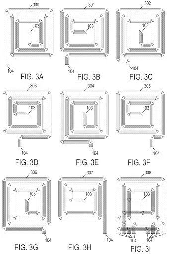
From the patent perspective, Momentum Dynamics uses a flat spiral structure and uses a specific way to connect it. The disadvantage is that it is not small in size and is not lightweight.
Prospects of Wireless Charging Development
Currently, the field where wireless charging for electric vehicles is more developed is in public road transportation.
Compared to fuel buses, electric buses are more environmentally friendly, and wireless charging is easier to supplement energy and make full use of fragmented time.
Compared to trams, wireless charging has advantages in urban planning and laying maintenance.
For wireless charging of electric vehicles, SAE’s J2954, which is divided into four levels for power below 22kW, is an important reference for the development of wireless charging standards for electric vehicles in various countries. However, only a few car companies have relevant development plans for this, as wireless charging has high requirements for distance and angle and needs the cooperation of sensors, otherwise the charging power will be poor.
High cost and low efficiency.
Due to the installation under the car, there is a risk of collision, and most importantly, many people have safety concerns for its electromagnetic waves.
Technical, cost and social reasons make wireless charging for private cars destined to be the choice of a few car companies.
Occasionally, we can see the promotion of high-speed highway lanes that can be charged while driving, but this is mostly a big talk with little significance.
Because the vast majority of electric vehicles are not equipped with receiving coils, they simply cannot be charged, and the metal debris and fragments on the highway will cause electromagnetic induction heating and pose safety hazards.
Therefore, the next time you see the promotion of wireless charging on high-speed highways, you should know that concepts are probably stronger than technology.
“`
This article is a translation by ChatGPT of a Chinese report from 42HOW. If you have any questions about it, please email bd@42how.com.
