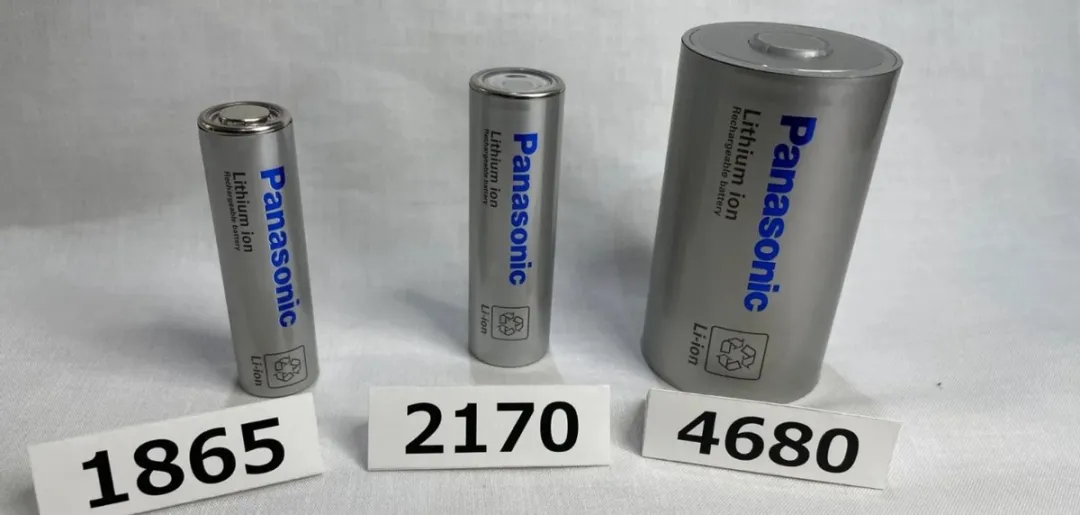
Energy Upgrade from 4680
I consulted with a friend in the supply chain industry for information about the 4680 large cylindrical battery cell. I excerpted some of the most valuable content and provided some rephrasing based on my understanding.

Manufacturer’s 4680 battery cell specification (currently estimated to be 0.65 yuan/kWh, should be lower than 21700):
Graphite + high-nickel: 26 Ah, energy density 283 Wh/kg
Silicon-carbon + high-nickel: 30 Ah, energy density 300 Wh/kg
By comparison, Panasonic’s earlier NCA had an energy density of 254.8 Wh/kg, and LG’s 811 battery cell had an energy density of 248 Wh/kg.


21700: 4 modules, over 4,400 battery cells, energy density of 170 Wh/kg
46800: no modules, 960 battery cells, energy density of 215 Wh/kg
In Tesla’s traditional arrangement, the 21700 typically has 4 modules: 2 large and 2 small. The weight of a 21700 battery cell is approximately 312 kg, using over 4,400 battery cells.
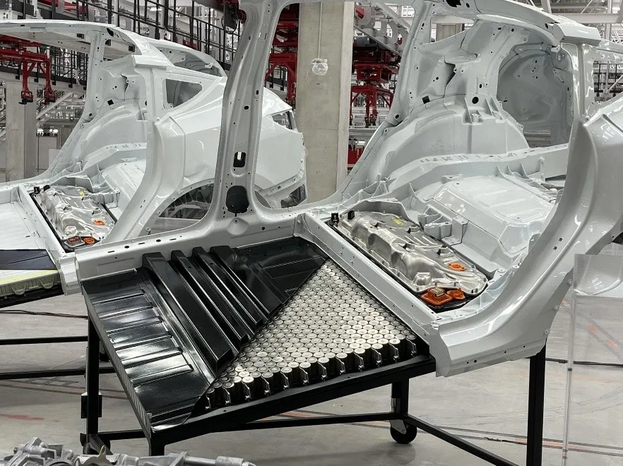
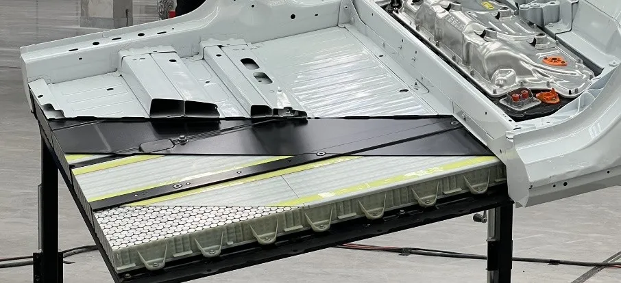
The 4680 design consists of 900+ battery cells arranged without a module. The weight of the structural component is only 12 kg due to the optimization in the BMS. The weight of the 960 battery cells used in 4680 is approximately 336 kg. The entire 4680 module is approximately 90 kg due to optimization. The weight of the battery pack is about 438 kg for 4680 compared to 474 kg for 21700. The energy density for 21700 pack is 170 Wh/kg while the 4680 pack is 215 Wh/kg.
Note: This data is from Tesla, and we have not seen it in person yet. This is unexpectedly high, and I personally think it has exceeded my imagination.
According to our research, the domestic version of the 4680 battery cell uses an 811 ternary high-nickel system for the positive electrode material and artificial graphite for the negative electrode (which may switch to silicon as development progresses).The working voltage of the battery cell is 2.8V-4.2V, with a designed fast charging time of 20 minutes to charge up to 80%. The weight of a single cell is approximately 355g, and a 1/3 C cycle life can achieve 1500 cycles (80% capacity retention).
Based on these design parameters, the CTC-based 4680 battery pack can achieve a capacity of 95 kWh, while the 21700 battery pack corresponds to 82 kWh, resulting in an increase of about 15% in battery pack capacity.
Currently, the main issues encountered in the manufacturing process of the 4680 battery cell are process matching and automated equipment matching. Compared to the manufacturing process of the 21700, there are some differences in the manufacturing process of the 4680. For example:
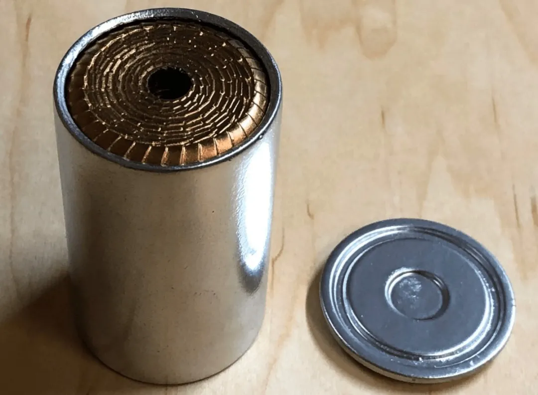
In the coating process, the consistent arc of the entire pole piece creates a higher precision requirement for the equipment. The amount of remaining blank space in the outer ring will be more than that in the inner ring.
The requirements for the slitting process are also higher. If the edges are uneven, there will be gaps when the pole pieces are assembled.
In terms of spot welding, laser spot welding of the entire pole piece will increase the number of welding points (more than five times that of the 21700).
During production, battery cell companies need to optimize the corresponding processes with equipment manufacturers to achieve an acceptable yield rate.
For Tesla, with the promotion of the 4680, two or three contract manufacturers will be needed in China to achieve greater production capacity. From a time frame perspective, domestic leading companies have also invested some resources in developing the 4680 and subsequent production lines, and are expected to start production (SOP) at the end of 2022 or the first half of 2023. Leading cylinder companies abroad may reach mass production in 2022.
Discussion on some processes
Based on research, there are two ways to implement consistent pole pieces:
1) Cut then wind: the material is cut into many pieces before winding, and the parts cut during winding are a straight line, which is then welded. With this process, the yield rate can reach 60%+.
2) Laser cutting then wind: the material is wound and then laser-cut at the blank copper foil. This requires high precision, and if there are gaps between the two copper foils, the laser energy will be greater, causing different inter-foil gaps and the possibility of cutting into the material, leading to inconsistent internal resistance. With this process, the yield rate can be increased to 70%+.

In terms of materials,
Positive electrode: The 811 system high-nickel cathode has not changed much from before.
Negative electrode: Silicon-oxygen-based material is more suitable, as silicon-carbon has a much larger volume expansion than silicon-oxygen, and is currently considered unsafe.Separator: Double-sided ceramic or one-side ceramic and one-side PVDF are used in the diaphragm. When using silicon negative electrode, one side may be ceramic while the other is coated with a layer of 1μm PVDF on the basis of ceramic. This is to suppress the expansion of silicon negative electrode. PVDF can retain the ion transfer channel, improve the stability of negative electrode powder on the electrode plate, prevent detachment, and increase cycle life.
Electrolyte: The electrolyte added with silicon negative electrode will be 6% less than that of high nickel.
Current collector: There is no significant change in the positive electrode foil.
Carbon nanotube: The conductive agent of the positive electrode is mainly carbon nanotube, which is mainly cooperated with multi-walled carbon nanotube and SP. The amount is about 1%. The purity of carbon nanotubes is required for the 811 system. If there are metal impurities, metal deposition will occur during use, affecting the material properties.
Adhesive: CMC and SBR are used in the graphite system, and improved SBR may be used after switching to the silicon negative electrode. Less CMC is added, and some carboxyl functional groups are added to SBR, so that some chemical bonds can be formed with silicon, which can stabilize the volume change during charge and discharge process. Another option is to use PA polyacrylic acid (not yet mature).
Summary: I think it’s quite useful for your reference.
This article is a translation by ChatGPT of a Chinese report from 42HOW. If you have any questions about it, please email bd@42how.com.