The overall impression of the Audi E-tron is that it uses too many MCUs and CAN transceivers in one battery pack. Although there are no problems when chip supplies are sufficient, difficulties arise when they are scarce, as it takes 15 MCUs, 14 SBCs, and 16+ CAN transceivers to get the battery pack up and running.
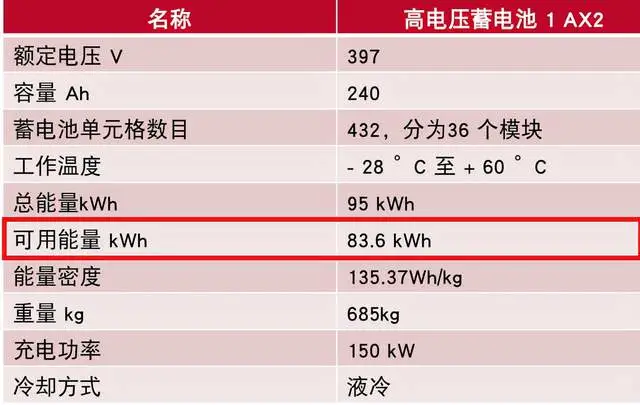
Audi’s usage strategy for the battery is relatively conservative, with a higher safety factor. The company tells users that the total battery capacity is 95kWh but only allows access to 83.6kWh for safety reasons, with the other 12% being locked away.
The fuse and relay pairings are separated for charging and discharging, which is advantageous for handling short circuits under different conditions and optimizing matching. Particularly for fast charging with high current, fuse specifications can be adjusted and paired.
Next, let’s take a closer look at some content that Audi has defined.
Some Definitions Set by Audi
- Why is the proportion of usable battery power so low?
Several of Audi’s battery systems have this problem. As shown in the figure below, for a 95kWh battery, only 83.6kWh can be used, which is significantly different from the proportion of usable energy in China.
Note: The upgrade for the E-tron will have a 110kWh battery pack.
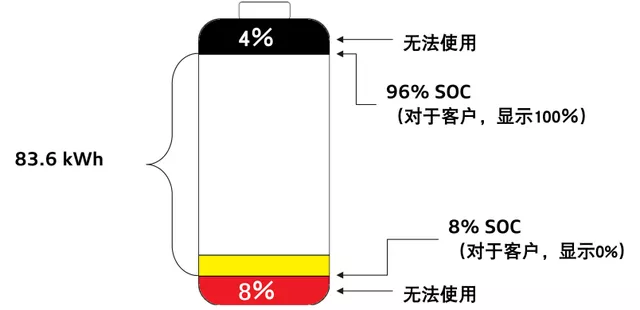
In reality, the engineers in Germany allocated 83.6kWh in the following way: a 4% upper limit and an 8% lower limit, which equates to 12% of energy that cannot be used (11.4kWh of energy). The image below shows that at an SOC of 8%, the driver is shown 0% and at 96%, they are shown 100%.
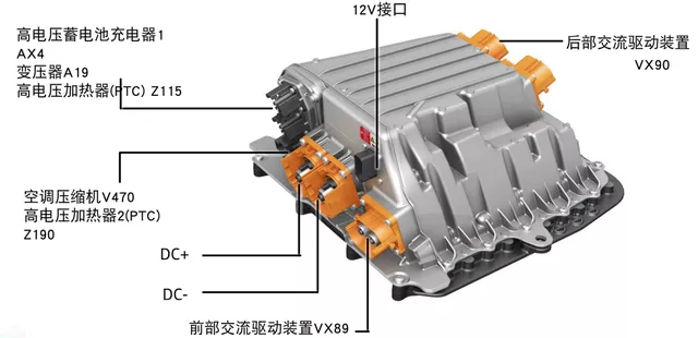
- BDU’s Internal Structure
The design structure of the BDU is shown below, which mainly includes several main interfaces such as rear drive, front drive, fast charging, and auxiliary distribution.
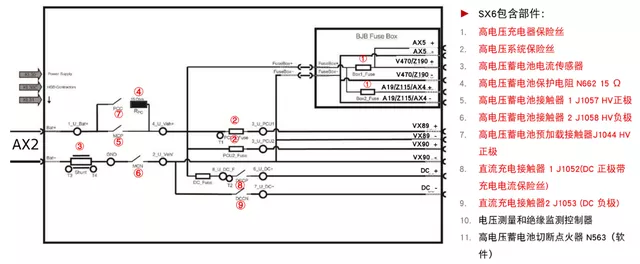
Based on this data, we can see the following information:
The pre-charge resistance is 15 ohms.
A total of 5 DC contactors are configured, including a pair of fast charging contactors and a pair of main positive, main negative, and pre-charge contactors for PCC.The configuration of the fuse is matched with the quick charge fuse and the quick charge foundation;
The front and rear drives are matched with the MCP and MCN main positive and negative, respectively, so that the fuse blowing time can be designed specifically when fast charging and driving short-circuit occur;
Considering the high possibility of the charger and other small fuses blowing, a BJB Fuse Box is separately made;
Composition of Battery Management System
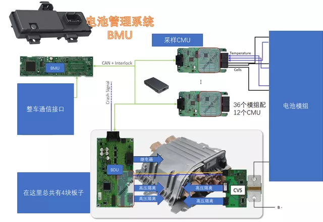
There are several boards here:
Battery management (provided by Marquardt and Dräxlmaier): I usually call it BMU, and Audi calls it BMC, which is placed outside the battery pack.

According to the disassembly information, the main chip MCU is SPC5746, the power chip is SBC MCZ33905 (including one CAN and one LIN), and the two external CAN transceivers are TJA1051. The chips for 2-channel high-side output are ST VN5E160S. BMU also retains a TI MSP430G223.
Sampling management: I usually call it CMU. Its functions are as follows. It uses CAN bus and 1 to 3 splitting. This habit has been carried forward to the design of MEB. The equalization strategy here requires the battery to be allowed when the SOC is at 30%, and balancing begins when the voltage difference of battery is at 1%.

According to the disassembly information, the chip used for AFE is MC33771, the MCU used is SPC5602D, the power supply used is NXP’s UJA1164, and the isolation used for AFE is transformer MU1228NL. The status detection of AFE is output through the optocoupler ACPL K49L.
BJB battery high voltage management (provided by Draxlmaier): The main purpose is to manage the high-voltage contactors and perform insulation checks every 30 seconds.“`markdown

According to the dismantling information, its power chip is SBC MC33908 (inheriting the CAN transceiver), and the main chip MCU is MPC5744P. The relay drive uses high-side ST VND5160 and low-side ST ND7NV04 switches.
For insulation detection, ADC (Microchip’s MCP3911) is used, and for high-voltage detection, LM2903 is used for sampling. TJA1042 transceiver is used for internal data transmission and reception.
In summary, we can simply add up here: excluding CVA’s shunt, a total of 15 MCU chips, 14 SBC chips, and a bunch of CAN transceivers are used. For distributed communication systems, the consumption of MCU chips in the battery pack system of an electric vehicle is basically enough for the use of a simple traditional car.
This can also reflect from another perspective that in terms of chip shortage, the situation in China is slightly better than that in foreign countries. There are differences in technology routes between China and foreign countries in terms of bus and hardware technology architecture.
“`
This article is a translation by ChatGPT of a Chinese report from 42HOW. If you have any questions about it, please email bd@42how.com.