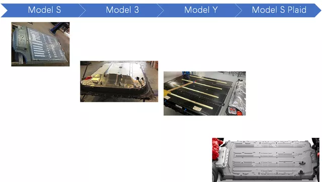
I want to write about the battery system design of the Model S Plaid and explore Tesla’s design philosophy. The reference information primarily comes from the Model S Plaid’s disassembly information and other related content.
Regarding the disassembly, we have observed the following with regards to the Model S Plaid battery design:
-The Model 3’s PCS (Charger+DCDC) design has been imported, with 11 kW being the standard onboard charging system.
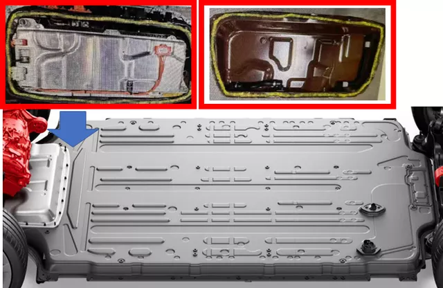
-The battery system includes two maintenance windows at the front and back, respectively, for the PCS and two sets of contactors (positive, negative, and quick charge contactors for twins).
-A maintenance window was specifically designed for the PyroFuse, as practical experience has shown that treating the PyroFuse as a separate defense line necessitates treating this component as a vulnerable part requiring separate maintenance.
-The metal shell connector from Model Y has been imported to shorten the length of the quick charge connection cable with the goal of 350 kW charging for high current applications in the future.
From the overall design philosophy perspective, we can see several particularly interesting aspects of Tesla’s design philosophy:
-Every platform is iterative, with some common excellent designs that can be transplanted in a modular fashion.
-Although the Model S and Model 3 are different platforms, after confirming excellent designs, they are quickly deployed on different platforms, and deployment is very fast.
-The iteration and update of individual platforms are towards continuous cost reduction and optimization while continuously improving.
The following shows a dual-motor version, and in reality, the Model S Plaid also has a front 1 and rear 2 drive configuration.
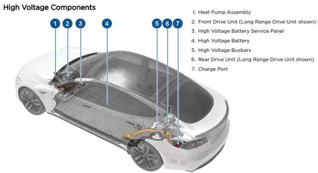
What is most impressive here is the electrical maintenance design of the Model S Plaid. Due to Tesla’s direction towards CTP, the company is particularly focused on the maintainability of its electrical designs.
(1)Service Panel 1
This part is associated with the battery and is located beneath the seats, as shown below.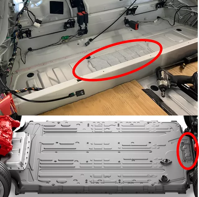
The main components under this panel are four contactors, including twin contactors for fast charging, and the main positive and negative contactors.
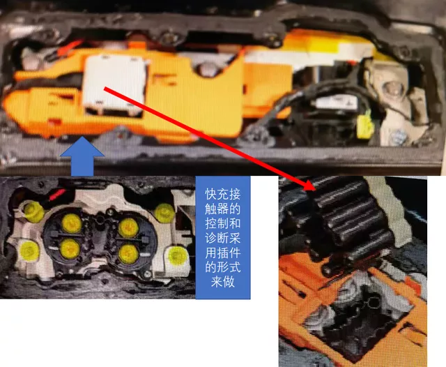
In order to minimize the heat generated by high currents, it can be seen that the design for the input part of the fast charging connector and the fast charging contactors is simplified as shown in the figure below.
Note: According to my connection, the continuous current design target is set to around 900A.

(2) Service Panel 2
The most interesting design here is that Tesla has designed a separate maintenance window for the PyroFuse at the bottom of the entire battery pack. The biggest advantage here is that PyroFuse has a more flexible replacement strategy. The car can be lifted up to replace it, which should be the biggest update in Tesla’s repair methods so far. It allows the quick-acting Pyro Fuse to disconnect to protect the entire battery and electrical system, and to replace the fuse after diagnosis.

(3) Service Panel 3
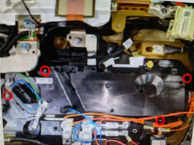
Inside this maintenance window, there are mainly two layers. The bottom layer includes small fuses and BMS, and the top layer includes PCS. This design logic is exactly the opposite of Model 3 and Model Y, where the PCS is at the bottom, and the BMS and fuses are at the top. I estimate that this is because the PCS needs to be repaired more frequently.
 The battery management system of Model S has adopted the design of Model 3 and Y, reducing the fuses from three to two which mainly removes the high voltage PTC. As long as the power supply to PCS and the compressor of the heat pump is provided, the overall maintenance frequency is greatly reduced.
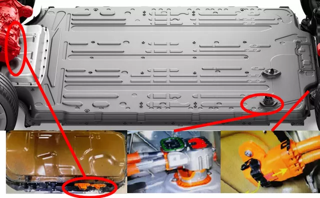
As for the overall high-voltage output of Model S Plaid, it adopts the method of internal package wiring as shown in the figure below:
The fast charging connector goes up to the top of the battery pack, and is connected to the cable in the car compartment through plug and cable, with a hole on the floor.
The rear-drive inverter connector is located at the bottom of the battery pack behind the car as shown in the figure below.
The front-drive inverter connector is connected to the protrusion and the compressor connector in front of the battery pack.
Tesla ultimately chose to use internal high-voltage busbars. From the overall design perspective, in Model S Plaid, the high-voltage cables for high current only have approximately 0.5 meters * 2 cores, which are used to connect the fast charging connectors and the input of the battery pack. The other front and rear drive inverters are only about 0.3 meters long, adding up to only 1 meter. The entire high-voltage cable operation has ended and has been replaced by internal high-voltage copper busbars. The low-current cable, which is from the front to the compressor, is only about 0.6 meters long.
Conclusion: So far, the high-voltage cable supply chain for this part of the market is very limited. Tesla’s approach of treating high-frequency safety components as maintenance parts is also very valuable as reference.
This article is a translation by ChatGPT of a Chinese report from 42HOW. If you have any questions about it, please email bd@42how.com.