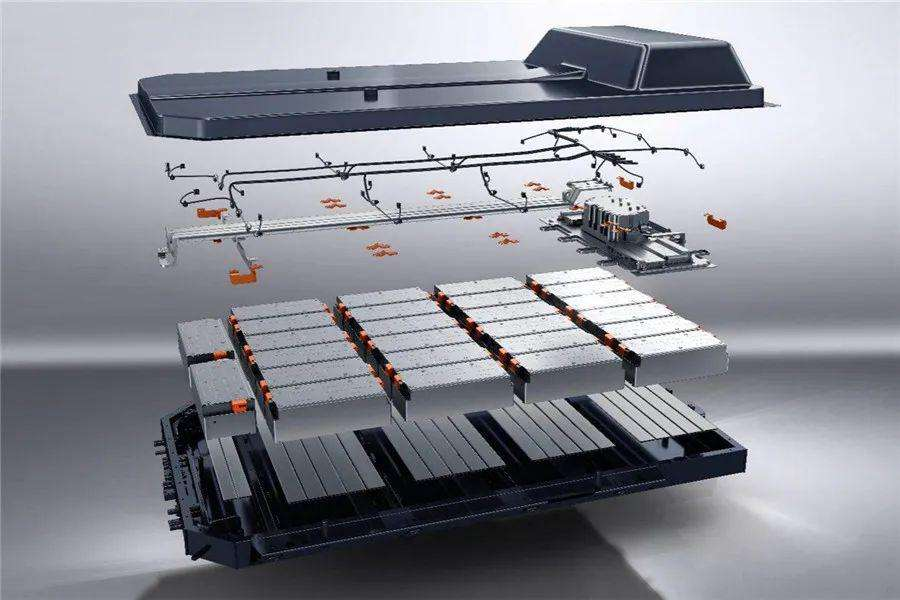
When browsing and organizing information online, I came across a disassembled blade battery system that nicely organizes some interesting parts. Of course, the part that I’m most interested in personally is the electronics and electrical systems. Today, I’ll share the content of this part first, and then will decompose the structure and cooling parts one by one in the future. Later on, I will have the opportunity to organize some professional institutions’ testing and analysis of blade batteries and make some excerpts.
On the left of the following figure is BYD’s 50kWh + low-power battery system, and on the right is a 70+kWh stacked dual-row battery system. They share a common feature, that is, BYD’s battery needs a relatively long main bus bar to be connected back.
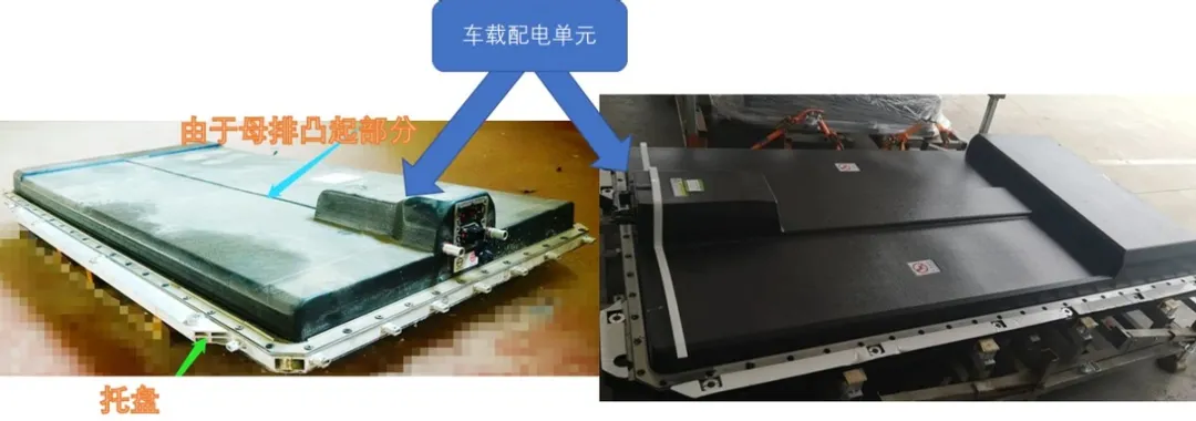
In the structured design, from an electrical standpoint, the ends of the entire battery need to be connected together. Therefore, we can see the two wide positive and negative main bus bars connecting the charged ends of the integrated battery to the BDU distribution box, as shown in the following figure.
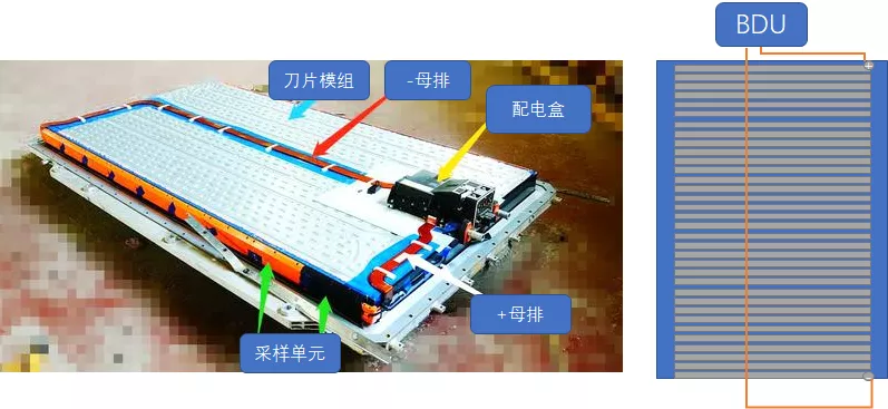
Note: According to the disassembly information referenced, the material of this main bus bar is aluminum.
And this BDU distribution box is a bit like the interface design we usually see on PHEVs, trying to reuse the protruding design of the middle exhaust pipe as much as possible. Blade batteries are compatible with both BEV and PHEV designs on the entire vehicle, so it currently appears that they are designed uniformly above the battery system.
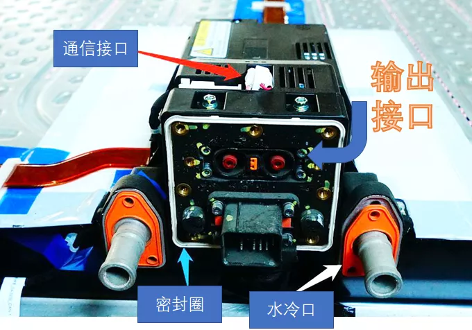
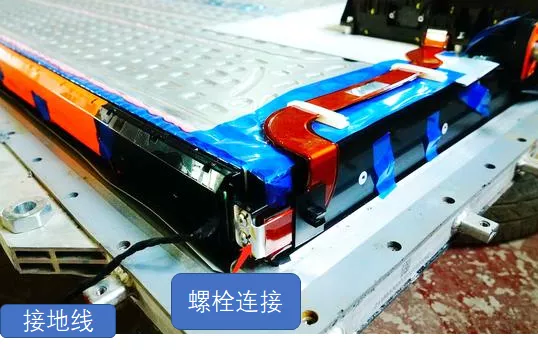
As shown in the following figure, the main bus bar is connected to the output polarities of the blade battery module through two bolts.
In order to fix this BDU, four fixing points are set on the water-cooled plate, and in order to perform electrical isolation, engineers use a square insulation pad to further strengthen insulation.
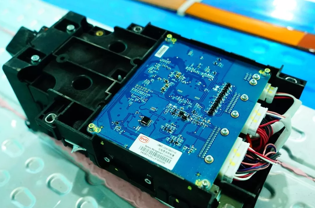
 The Battery Management System (BMS) is integrated in this power distribution box. It should be noted that the BMU here no longer has an independent shell and is embedded in the BDU, which is then screwed on with a cover plate.
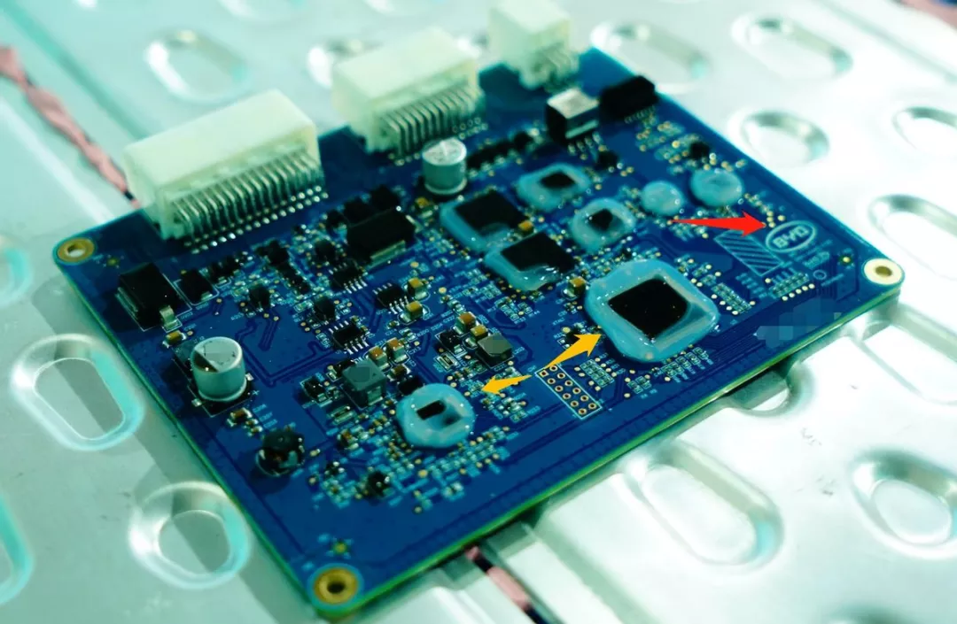
For some reason, BYD’s circuit boards now tend to have these types of adhesive coatings in certain areas.
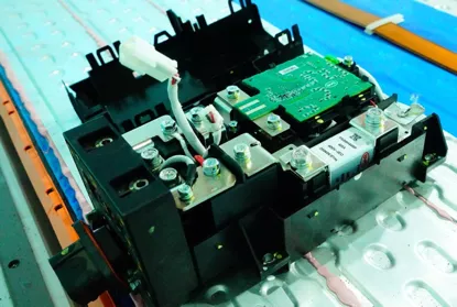
There are two main contactors installed in the battery management system, with a BYD self-made shunt current sensor and a 400A fuse in the circuit.
Summary: I came home late today, so I will stop here for now. When I have time, I will write the second part of this series on BYD’s BMU and CMU.
This article is a translation by ChatGPT of a Chinese report from 42HOW. If you have any questions about it, please email bd@42how.com.
